4 layers100 × 100 mm
Dac16
tombueng/hilprobe
HILprobe: multi-function UUT probe for hardware-in-the-loop testing - RS-485, CAN FD, logic analyzer, 4-ch scope, two programmable UUT supplies. KiCad 10, 6 layers, RP2350B + ESP32-S3.
200 parts

 tombueng/hilprobe
HILprobe: multi-function UUT probe for hardware-in-the-loop testing - RS-485, CAN FD, logic analyzer, 4-ch scope, two programmable UUT supplies. KiCad 10, 6 layers, RP2350B + ESP32-S3.
Buslab is an open-source printed circuit board by tombueng, from the tombueng/hilprobe repository on GitHub. It is a 6-layer board of 160 × 100 mm with 429 parts on 393 nets, routed with 3,758 tracks and 1,441 vias.
It is built around the THVD2450D, 74HCT541D and OPA2365AID, with the TCA9534PW, GAQY212GS and SN74LVC1G3157DCKR among its other parts. Its parts include 147 capacitors, 119 resistors, 49 ICs, 20 diodes and 10 transistors. It belongs with the sensors and measurement and interfaces and adapters boards and the ESP32 and RP2350 boards of this library.


A multi-function probe for a unit under test (UUT), made to be driven by hardware-in-the-loop and automated test tooling. One board powers the UUT, talks on its buses, watches its pins and measures what it draws, all on one timebase, remote-controlled over USB, WiFi or Ethernet. Internal project name: BusLab.
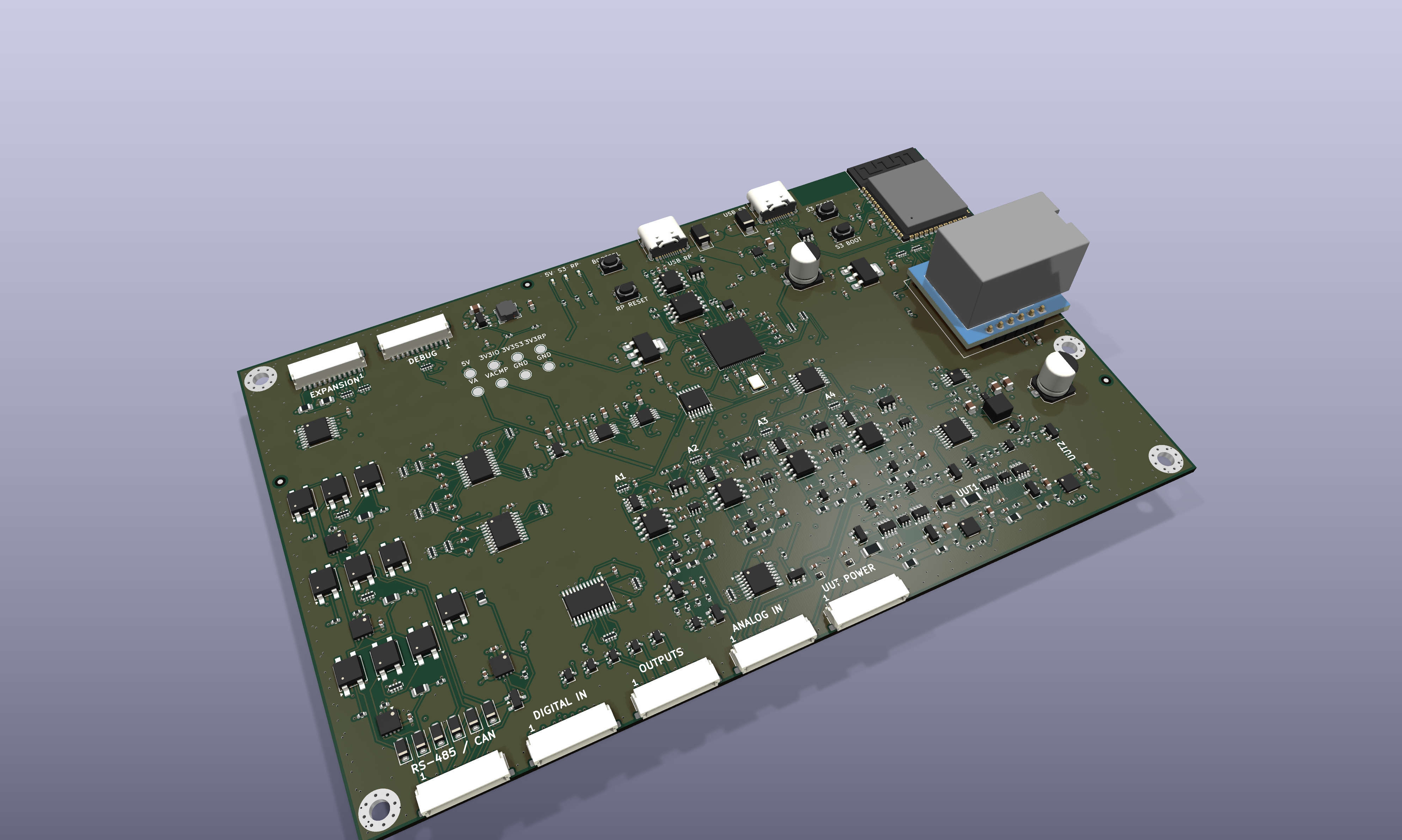
Status (2026-10-06): schematic, placement and routing done, pre-fab review and rework done (docs/PREFAB_REVIEW.md); KiCad DRC, the JLCPCB DFM check and an EMC field check are clean. Not yet manufactured or tested. Firmware is not written yet: the hardware numbers below are the design's, the functions marked firmware are planned (docs/FIRMWARE_NOTES.md, spec/).
| Analog inputs | 4 channels A1-A4, 1 MΩ ∥ 19 pF, DC coupled, ranges ±10 V and ±30 V per channel by firmware (×10 probe compensation holds on both); max ±50 V continuous, ±100 V peak. About 10 MHz bandwidth to the ADC, more to the comparators. RP2350 ADC: 12 bit (9.2 ENOB), 500 kS/s shared (125 kS/s per channel with all four), 1 LSB 5.4 mV (±10 V) / 16 mV (±30 V). Assembly option: 4 × ADS7883, 2 MS/s per channel, sampled simultaneously |
| Comparators | 2 per analog channel (threshold and window), TLV3502, 9-21 ns, 6 mV hysteresis, 12-bit thresholds (2 × MCP4728): dips from 100 ns are caught |
| Digital inputs | 10 channels D1-D10 through 74HCT541, TTL thresholds (low < 0.8 V, high > 2.0 V: 3.3 V and 5 V logic), signals to 10 MHz, sampled up to 100 MS/s (firmware), 10 kΩ ∥ 47 pF series input, max ±24 V continuous, open inputs read low |
| Outputs | OUT1-4 (ESP32-S3) and TRIG OUT (RP2350) through SN74LVC8T245, level off / 1.8 / 2.5 / 3.3 / 5.0 V by firmware (TLV75801P), 330 Ω series, Schottky clamps, high-impedance at power-up |
| RS-485 | 3 ports, THVD2450 (50 Mbit/s, 1/8 unit load, ±70 V fault, ±25 V common mode), half duplex; 120 Ω termination and 330 Ω fail-safe bias per port behind photoMOS switches, all off at power-up (passive listener); TVS on every line |
| CAN | CAN FD up to 5 Mbit/s, TCAN1051HGV (±70 V fault, ±30 V common mode), switchable 120 Ω, listen-only at power-up |
| UUT power | 2 outputs, 0.8-5.0 V in 1.2 mV steps, 500 mA each, an AP7361C-ADJ LDO per output fed from a 5.28 V boost (TPS61023), set by a 12-bit DAC (MCP4822). Step up ~0.2 ms, down 0.2-1.3 ms (discharge FET). Current: INA236 + INA190 with automatic range switching, 0.25 µA steps to 8 mA, 17 µA steps to 540 mA. Protection: firmware trip, 1.1 A hard limit, over-current alert switches the LDO off in hardware, off at power-up; dissipation (5.3 V − Vout) × I ≤ 1.5 W per output. Not for feeding an external supply back |
| Trigger | TRIG IN (TTL, ±30 V), TRIG OUT (pulse at the trigger, at the output level); sources: TRIG IN, comparators, windows, digital patterns, RS-485 / CAN frames, the ESP32-S3. One timebase for analog, digital, RS-485 and CAN |
| Instrument MCU | RP2350B (chip-down, Raspberry Pi's reference circuit), 150 MHz, PIO capture of all inputs on one clock, 16 MB QSPI flash, 8 MB PSRAM for long captures |
| Gateway MCU | ESP32-S3-WROOM-1-N16R8 (16 MB flash, 8 MB PSRAM): USB, WiFi, Ethernet, CAN, the outputs, scripts; SPI link to the RP2350, updates it over SWD |
| Network | WiFi (ESP32-S3); Ethernet 10/100 with a USR-ES1 (W5500) module soldered on, optional |
| USB | two USB-C sockets: ESP32-S3 (USB serial / JTAG, control) and RP2350 (hold BOOTSEL and plug in: UF2 drive; development and standalone use) |
| Power | 5 V from either USB-C socket (TPS2121 power mux, highest input wins); cut-off above 5.2-5.7 V, TVS and USB ESD on both, 220 µF hold-up; about 0.37 A typical, 1.2 A peak, 2.4 A with both UUT outputs at 500 mA (a 3 A USB-C source) |
| Expansion | I²C, 3 spare GPIOs (100 Ω series; E1 is a 3.3 V-only RP2350 pin), 3.3 V and 5 V out through 200 mA PTCs |
| Debug | SWD and RUN of the RP2350, ESP32-S3 console; test pads for 5 V, 3V3 IO, 3V3 S3, 3V3 RP, VA, VA CMP, GND |
| Connectors | seven JST SH 12-pin, 1.0 mm pitch (board: SM12B-SRSS-TB; cable: housing SHR-12V-S or SHR-12V-S-B, contacts SSH-003T-P0.2-H for AWG 32-28); pins 11 and 12 are GND on every one except EXPANSION |
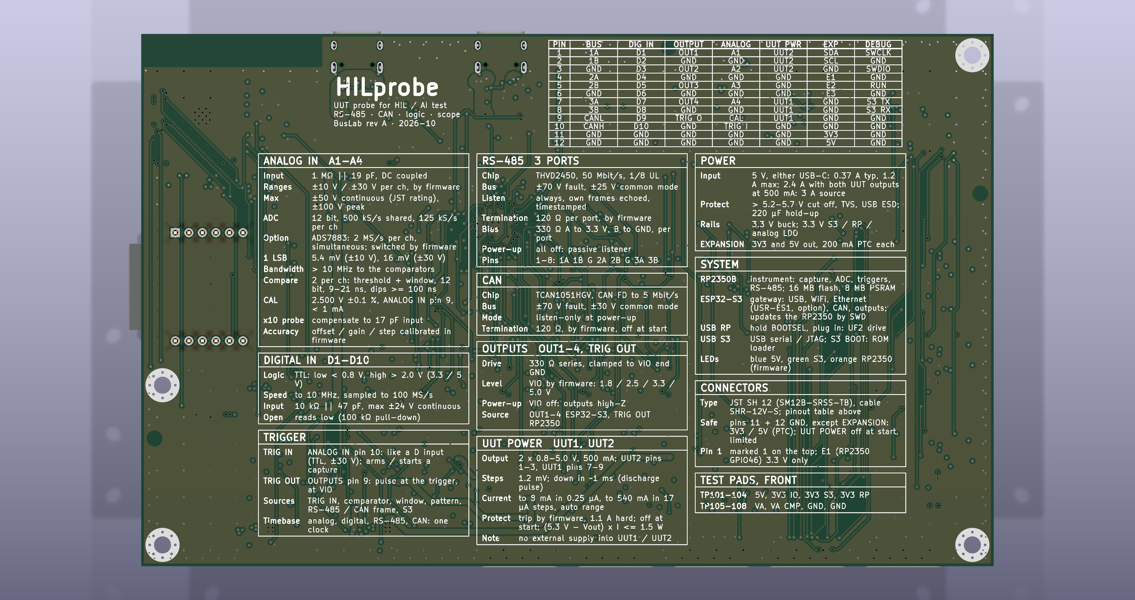
| Board | 160 × 100 mm (Eurocard), 6 layers (JLC06161H-2116A, two solid GND planes), all parts on the top side for machine assembly, four M3 holes; the back carries the pin table and a data sheet of the board |
All seven are JST SH 12. The table is printed on the back of the board.
| Pin | RS-485 / CAN | DIGITAL IN | OUTPUTS | ANALOG IN | UUT POWER | EXPANSION | DEBUG |
|---|---|---|---|---|---|---|---|
| 1 | 1A | D1 | OUT1 | A1 | UUT2 | SDA | SWCLK |
| 2 | 1B | D2 | GND | GND | UUT2 | SCL | GND |
| 3 | GND | D3 | OUT2 | A2 | UUT2 | GND | SWDIO |
| 4 | 2A | D4 | GND | GND | GND | E1 | GND |
| 5 | 2B | D5 | OUT3 | A3 | GND | E2 | RUN |
| 6 | GND | D6 | GND | GND | GND | E3 | GND |
| 7 | 3A | D7 | OUT4 | A4 | UUT1 | GND | S3 TX |
| 8 | 3B | D8 | GND | GND | UUT1 | GND | S3 RX |
| 9 | CANL | D9 | TRIG O | CAL | UUT1 | GND | GND |
| 10 | CANH | D10 | GND | TRIG I | GND | GND | GND |
| 11 | GND | GND | GND | GND | GND | 3V3 | GND |
| 12 | GND | GND | GND | GND | GND | 5V | GND |
CAL is a 2.500 V ±0.1 % reference (LM4040A) for calibrating the analog channels.
| Path | What |
|---|---|
hw/ | KiCad 10 project: schematic sheets, board, design rules, custom footprints and symbols, 3D models |
export/fab/ | Gerbers and drill (buslab-gerber.zip), pick-and-place for JLCPCB (buslab-cpl.csv) |
export/bom/ | BOMs: JLCPCB assembly (jlcpcb-reduced.csv, jlc-all-bom.csv), self-sourced (Reichelt, TME), hand-fitted parts |
export/ | schematic PDF, STEP model, raytraced renders |
docs/ | design and decisions, analog front end, PCB rules, placement, routing, EMC checklist, pre-fab review, firmware notes, toolchain |
ASSEMBLY.md, BRINGUP.md | assembly options and the bring-up sequence for the first board |
tools/ | the generators: circuit in Python to schematic and netlist, footprints, placement, an own router, checks, BOM / CPL, shop lookups, SPICE simulations, the EMC field-check scenario |
spec/ | the original requirements for hardware and software |
Everything in hw/ and export/ is generated by tools/ (see docs/TOOLCHAIN.md):
the circuit is written in Python, placement and routing are scripts, and tools/pcb/fab.sh turns the
board into the fabrication outputs. Requires KiCad 10 (kicad-cli and the pcbnew Python module),
Python 3 and ngspice; tools/setup.sh sets up the rest.
The board was run through emcvisual, with 28 sources
(clocks, buses, USB, switching regulators) whose values come from the datasheets
(hw/buslab.scenario.json, written by tools/emc/buslab_scenario.py). To look at it in 3D:
open the board in emcvisual,
then "Load scenario" with hw/buslab.scenario.json. Results and what was changed:
docs/EMC_CHECKLIST.md.
Datasheets, application notes and the TI SPICE models the design was checked against belong to their makers and are not redistributed here. hw/datasheets/SOURCES.md lists every document by name (with a link where one is known), tools/frontend/models/README.md where to get the SPICE models.
hw/, export/, docs/, the Markdown files): CERN Open
Hardware Licence Version 2 - Permissive (LICENSES/CERN-OHL-P-2.0.txt).tools/): MIT (LICENSES/MIT.txt).hw/datasheets/core2350b/thirdparty_kicad/ (MIT, see its LICENSE.md).Copyright 2026 Thomas Büngener.
| Qty | Value | Footprint | References |
|---|---|---|---|
| 70 | 100n | Capacitor_SMD:C_0402_1005Metric | C103, C106, C111, C114, C117, C119, C120, C1001, C1002, C1005, C1101, C1201, C1301, C1501, C1502, C1607 +54 |
| 25 | 1u | Capacitor_SMD:C_0402_1005Metric | C101, C102, C109, C112, C115, C118, C203, C506, C511, C512, C1003, C1004, C1605, C1606, C1702, C1802 +9 |
| 19 | 100k | Resistor_SMD:R_0402_1005Metric | R107, R109, R110, R403, R508, R1602, R1704, R1710, R1711, R1712, R1715, R1804, R1810, R1811, R1812, R1815 +3 |
| 15 | 2.0k | Resistor_SMD:R_0402_1005Metric | R401, R402, R505, R506, R507, R605, R606, R607, R705, R706, R707, R805, R806, R807, R1401 |
| 12 | 10k | Resistor_SMD:R_0402_1005Metric | R203, R205, R206, R215, R303, R1107, R1207, R1307, R1503, R1603, R1713, R1813 |
| 11 | 47p | Capacitor_SMD:C_0402_1005Metric | C901, C902, C903, C904, C905, C906, C907, C908, C909, C910, C911 |
| 10 | GAQY212GS | Package_SO:SO-4_4.4x4.3mm_P2.54mm | U1101, U1102, U1103, U1201, U1202, U1203, U1301, U1302, U1303, U1501 |
| 8 | 22u | Capacitor_SMD:C_0603_1608Metric | C108, C110, C113, C116, C201, C204, C402, C404 |
| 8 | 330R | Resistor_SMD:R_0402_1005Metric | R1001, R1103, R1105, R1203, R1205, R1303, R1305, R1502 |
| 8 | 330p | Capacitor_SMD:C_0402_1005Metric | C503, C505, C603, C605, C703, C705, C803, C805 |
| 8 | 470k | Resistor_SMD:R_0603_1608Metric | R501, R502, R601, R602, R701, R702, R801, R802 |
| 8 | 4x33R | Resistor_SMD:R_Array_Convex_4x0402 | RN201, RN202, RN206, RN207, RN502, RN602, RN702, RN802 |
| 7 | 33R | Resistor_SMD:R_0402_1005Metric | R213, R214, R301, R510, R610, R710, R810 |
| 7 | 4x330R | Resistor_SMD:R_Array_Convex_4x0402 | RN907, RN908, RN909, RN1001, RN1101, RN1201, RN1301 |
| 6 | BAT54SW | Package_TO_SOT_SMD:SOT-323_SC-70 | D1001, D1002, D1003, D1004, D1005, D1601 |
| 6 | SMF28CA | Diode_SMD:D_SOD-123F | D1101, D1102, D1201, D1202, D1301, D1302 |
| 5 | 10u | Capacitor_SMD:C_0805_2012Metric | C104, C107, C1601, C1602, C1603 |
| 5 | 2N7002 | Package_TO_SOT_SMD:SOT-23 | Q1002, Q1701, Q1704, Q1801, Q1804 |
| 5 | 4.7k | Resistor_SMD:R_0402_1005Metric | R112, R217, R304, R1707, R1807 |
| 5 | 47k | Resistor_SMD:R_0402_1005Metric | R1002, R1702, R1708, R1802, R1808 |
| 5 | 4x100k | Resistor_SMD:R_Array_Convex_4x0402 | RN901, RN903, RN905, RN1002, RN1003 |
| 5 | 4x10k | Resistor_SMD:R_Array_Convex_4x0402 | RN203, RN204, RN902, RN904, RN906 |
| 5 | JST SH 12 | BusLabCustom:JST_SH_SM12B-SRSS-TB_1x12-1MP_P1.00mm_Horizontal_EdgeOverhang | J1401, J1402, J1403, J1404, J1405 |
| 4 | 105k | Resistor_SMD:R_0402_1005Metric | R504, R604, R704, R804 |
| 4 | 10u | Capacitor_SMD:C_0603_1608Metric | C1701, C1703, C1801, C1803 |
| 4 | 120R | Resistor_SMD:R_0805_2012Metric | R1101, R1201, R1301, R1501 |
| 4 | 18p/100V | Capacitor_SMD:C_0603_1608Metric | C501, C601, C701, C801 |
| 4 | 4.7p | Capacitor_SMD:C_0402_1005Metric | C504, C604, C704, C804 |
| 4 | 4.7u | Capacitor_SMD:C_0402_1005Metric | C312, C313, C314, C318 |
| 4 | 5.1k | Resistor_SMD:R_0402_1005Metric | R101, R102, R103, R104 |
| 4 | 95.3k | Resistor_SMD:R_0402_1005Metric | R503, R603, R703, R803 |
| 4 | ADS7883 | Package_TO_SOT_SMD:SOT-23-6 | U503, U603, U703, U803 |
| 4 | BAV199W | Package_TO_SOT_SMD:SOT-323_SC-70 | D501, D601, D701, D801 |
| 4 | INA236 | Package_TO_SOT_SMD:TSOT-23-8 | U1702, U1703, U1802, U1803 |
| 4 | M3 | MountingHole:MountingHole_3.2mm_M3_Pad_Via | H1401, H1402, H1403, H1404 |
| 4 | OPA2365 | Package_SO:SOIC-8_3.9x4.9mm_P1.27mm | U501, U601, U701, U801 |
| 4 | SN74LVC1G3157 | Package_TO_SOT_SMD:SOT-363_SC-70-6 | U502, U602, U702, U802 |
| 4 | TCA9534 | Package_SO:TSSOP-16_4.4x5mm_P0.65mm | U403, U404, U1003, U1603 |
| 4 | TLV3502 | Package_TO_SOT_SMD:SOT-23-8 | U504, U604, U704, U804 |
| 3 | 20k | Resistor_SMD:R_0402_1005Metric | R1003, R1703, R1803 |
| 3 | 2N7002DW | Package_TO_SOT_SMD:SOT-363_SC-70-6 | Q1001, Q1703, Q1803 |
| 3 | FID | BusLabCustom:Fiducial_1mm_Mask2mm_Keepout3mm | FID1401, FID1402, FID1403 |
| 3 | THVD2450 | BusLabCustom:VSON-8-1EP_3x3mm_P0.65mm_EP1.6x2.4mm_EP5 | U1104, U1204, U1304 |
| 2 | 0.15R 1% | Resistor_SMD:R_0805_2012Metric | R1706, R1806 |
| 2 | 1.0k | Resistor_SMD:R_0402_1005Metric | R1709, R1809 |
| 2 | 10R 1% | Resistor_SMD:R_0603_1608Metric | R1705, R1805 |
| 2 | 15k | Resistor_SMD:R_0402_1005Metric | R1701, R1801 |
| 2 | 15p | Capacitor_SMD:C_0402_1005Metric | C321, C322 |
| 2 | 1k | Resistor_SMD:R_0402_1005Metric | R302, R305 |
| 2 | 200mA hold | Fuse:Fuse_0805_2012Metric | F201, F202 |
| 2 | 220u 10V polymer | Capacitor_SMD:CP_Elec_6.3x7.7 | C105, C1604 |
| 2 | 22R | Resistor_SMD:R_1206_3216Metric | R1714, R1814 |
| 2 | 24k | Resistor_SMD:R_0402_1005Metric | R106, R108 |
| 2 | 27R | Resistor_SMD:R_0402_1005Metric | R201, R202 |
| 2 | 74HCT541 | Package_SO:TSSOP-20_4.4x6.5mm_P0.65mm | U901, U902 |
| 2 | AO3400A | Package_TO_SOT_SMD:SOT-23 | Q1702, Q1802 |
| 2 | AP7361C-3.3 | Package_TO_SOT_SMD:SOT-223-3_TabPin2 | U105, U106 |
| 2 | AP7361C-ADJ | BusLabCustom:Diodes_U-DFN3030-8_TypeE_ThermalVias | U1701, U1801 |
| 2 | GND | TestPoint:TestPoint_Pad_D2.0mm | TP107, TP108 |
| 2 | INA190A4 | Package_TO_SOT_SMD:SOT-363_SC-70-6 | U1704, U1804 |
| 2 | JST SH 12 | Connector_JST:JST_SH_SM12B-SRSS-TB_1x12-1MP_P1.00mm_Horizontal | J201, J202 |
| 2 | SMAJ5.0A | Diode_SMD:D_SMA | D101, D102 |
| 2 | TLV7011 | Package_TO_SOT_SMD:SOT-353_SC-70-5 | U1705, U1805 |
| 2 | TPD1E10B06 | Diode_SMD:D_SOD-882 | D1701, D1801 |
| 2 | TYPE-C-31-M-12 | Connector_USB:USB_C_Receptacle_HRO_TYPE-C-31-M-12 | J101, J102 |
| 2 | USBLC6-2SC6 | Package_TO_SOT_SMD:SOT-23-6 | U101, U102 |
| 1 | +3V3_IO | TestPoint:TestPoint_Pad_D2.0mm | TP102 |
| 1 | +5V | TestPoint:TestPoint_Pad_D2.0mm | TP101 |
| 1 | 1.5k | Resistor_SMD:R_0402_1005Metric | R218 |
| 1 | 12MHz ABM8-272-T3 | Crystal:Crystal_SMD_3225-4Pin_3.2x2.5mm | Y301 |
| 1 | 18k | Resistor_SMD:R_0402_1005Metric | R1005 |
| 1 | 1u SWPA4030 | Inductor_SMD:L_Sunlord_SWPA4030S | L1601 |
| 1 | 2.2u SRN4018 | Inductor_SMD:L_Bourns-SRN4018 | L101 |
| 1 | 22k | Resistor_SMD:R_0402_1005Metric | R111 |
| 1 | 27k | Resistor_SMD:R_0402_1005Metric | R105 |
| 1 | 3.3u AOTA | BusLabCustom:L_Abracon_AOTA-B201610_PolarityDot | L301 |
| 1 | 39k | Resistor_SMD:R_0402_1005Metric | R1004 |
| 1 | 3V3_RP | TestPoint:TestPoint_Pad_D2.0mm | TP104 |
| 1 | 3V3_S3 | TestPoint:TestPoint_Pad_D2.0mm | TP103 |
| 1 | 4x100R | Resistor_SMD:R_Array_Convex_4x0402 | RN205 |
The 399 most common of 429 parts.
tombueng/hilprobe
HILprobe: multi-function UUT probe for hardware-in-the-loop testing - RS-485, CAN FD, logic analyzer, 4-ch scope, two programmable UUT supplies. KiCad 10, 6 layers, RP2350B + ESP32-S3.


Filip-Kin/frc-radio-kiosk
Bench box that powers and configures FRC radios: dual-mode PoE (802.3at via LTC4279, passive 12 V via TPS26600), USB-C PD or DC in, 15.6 V out for the Toughbook, 4x CR123A backup, STM32F072 firmware.


Bongorian/M5basspiezohat
M5StickS3 Hat2 five-channel bass piezo ADC board: KiCad design, TDM audio acquisition and JLCPCB fabrication data


gallicchio/AMOD-and-RFMOD
The tutorial's 2x12 adapter (/mudd/133electronics/icepi-zero-dac-adc/adapterboard/) with a 2 x 6 right-angle Pmod socket on a 15 mm extension of its right-hand end, so an Icepi Zero can drive AMOD-A's and RF-MOD's Pmod…
It measures 160 × 100 mm and has 6 copper layers, 1.6 mm thick.
429 parts, built around the THVD2450D, 74HCT541D, OPA2365AID and TCA9534PW. The full list of its parts is on this page, with links to each part's symbol and footprint where PCBKit's library has them.
From the tombueng/hilprobe repository on GitHub, at the commit this page was made from: the board is hw/buslab.kicad_pcb and its schematic addons/dac16/hw/dac.kicad_sch. PCBKit opens the board in the browser, with nothing to install.
Its repository states no licence, so its author keeps all rights: ask tombueng before reusing the design.