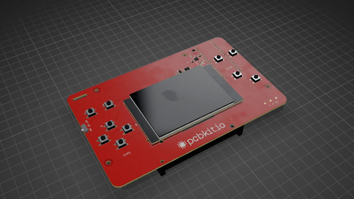
 Play in your browser
Doom handheld
A real Doom handheld: an RP2350 (Pico Plus 2) under a 2.8″ ILI9341 screen with ten buttons, on a routed red keycard.
Ready to order44 parts2 layersGPL-2.0
Product
The same Rust core runs in your browser, behind your agent, in your terminal and in CI. It places, routes, checks, simulates, runs the firmware and exports what a factory needs and it gives the same answer everywhere.
The app
Start a board, open one of 8,500+ open boards, drop a KiCad project or open one from GitHub. No sign-up. Everything runs in the tab, on your computer’s cores.
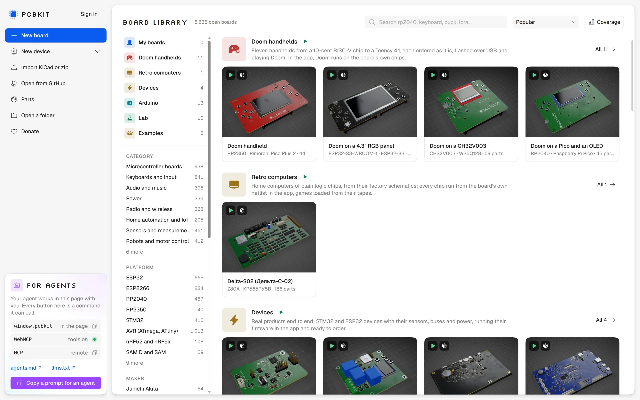
Regulators, USB-C power, LEDs, buttons, crystals, sensor ports. Each block works out its own part values from the numbers you give it and warns you when they don’t add up.
Say what a part must meet (10 kΩ, 1 %, 0402) and PCBKit picks one in stock and tells you why that one.
Your agent reads a datasheet into a part sheet; PCBKit checks the pins against the package and the land pattern against the standard before it goes on the board.
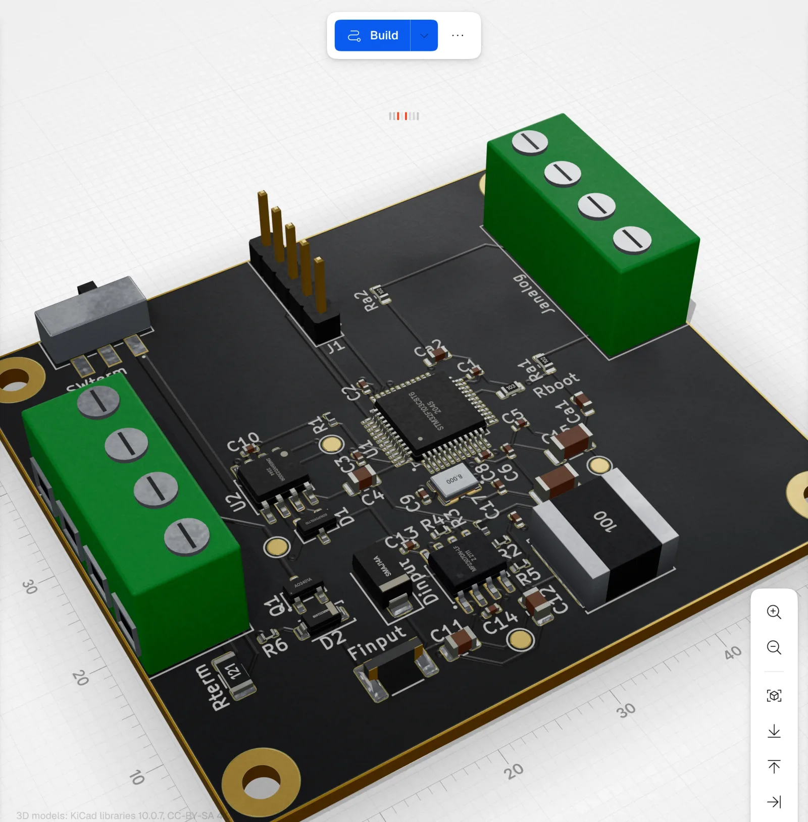
The board in 3D as the factory will make it: mask, finish and parts on their pads, its layers lifted apart.
Every change, yours or your agent’s, is one step in the history. Try things. Nothing is lost.
One link anyone can open, no account needed: your board read-only, its AI tour first, following your changes.
Agents
One plugin for Claude Code, Codex, Claude and ChatGPT. It gives your agent PCBKit’s tools and teaches it how to use them, so it designs boards instead of guessing. Every call says why it runs and you watch it on your board.
Add the marketplace and install the plugin.
claude plugin marketplace add pcbkit-io/plugins
claude plugin install pcbkit@pcbkitThe same repository is a Codex marketplace.
codex plugin marketplace add pcbkit-io/plugins
codex plugin add pcbkit@pcbkitAdd a custom connector in the settings with this address.
https://mcp.pcbkit.io/mcpThen ask: Make a board with an LED that blinks every 2 seconds.
Lab and firmware
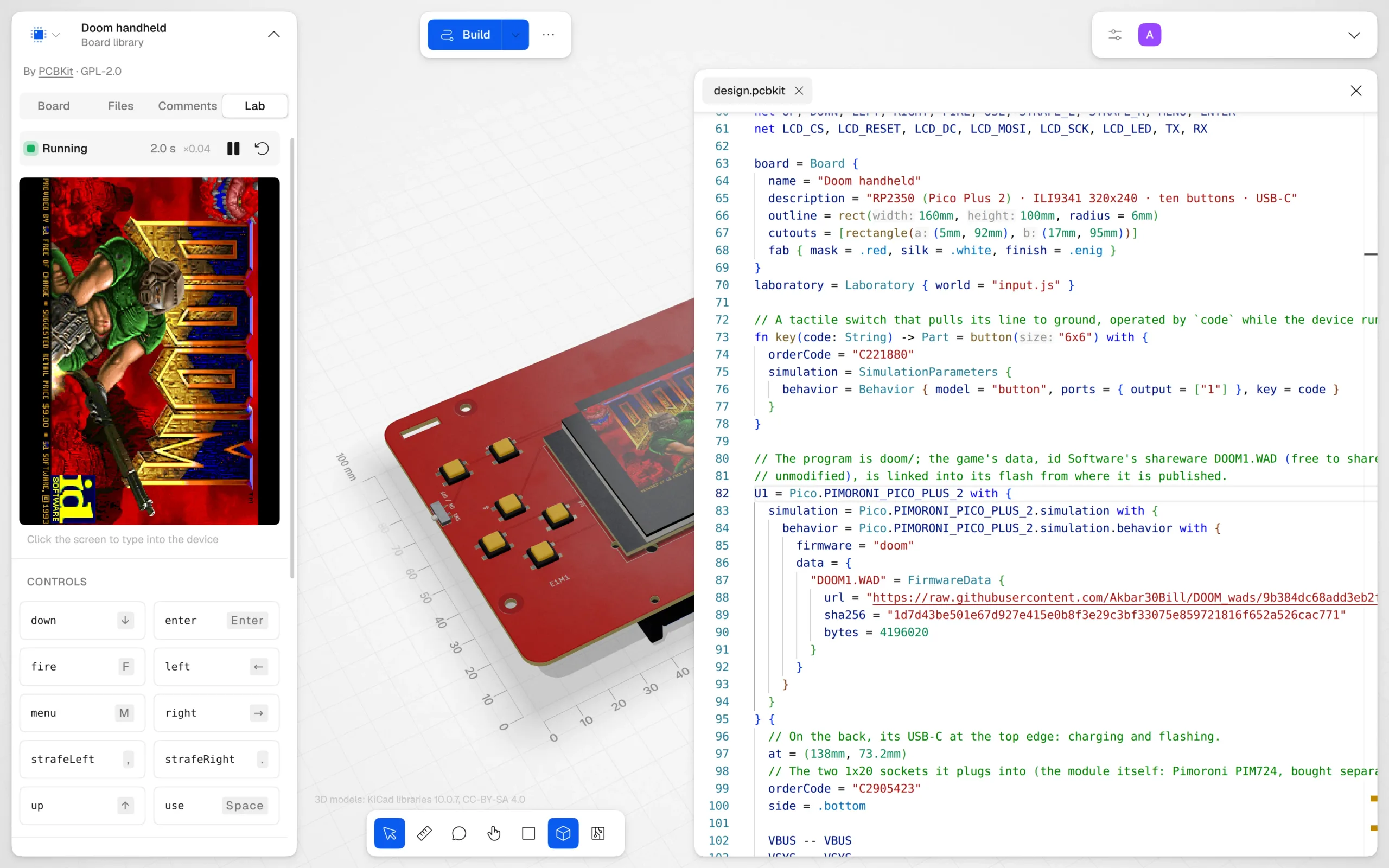
Design the board, write its firmware, press Run. PCBKit compiles the code in the browser tab and runs the image on models of the board’s own chips, screen and buttons included: the same image you flash onto the board when it arrives. We built eleven Doom handhelds to prove it.
11
Doom handhelds, every one routed, checked and ready to order
7
processors: RP2040, RP2350, ESP32-S3, ESP32-C3, STM32F411, i.MX RT1062, CH32V003
3
instruction sets in the page: Arm, RISC-V and Xtensa
0
things to install: the compilers run in your browser tab
Play in your browserA real Doom handheld: an RP2350 (Pico Plus 2) under a 2.8″ ILI9341 screen with ten buttons, on a routed red keycard.
Ready to order44 parts2 layersGPL-2.0
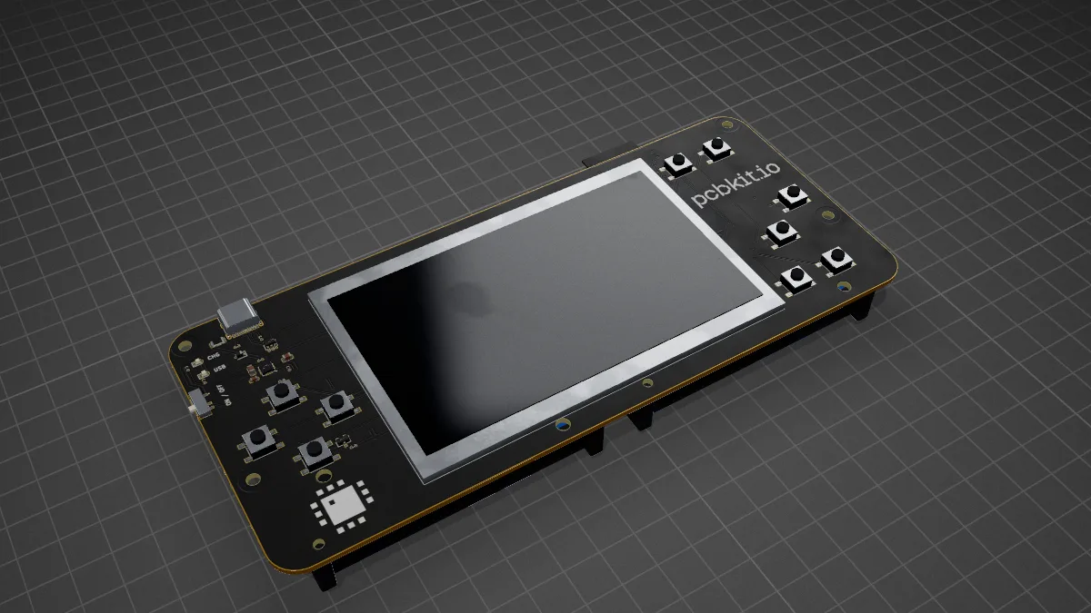 Play in your browser
The big-screen ESP32-S3: its LCD_CAM scans a raw 480 × 272 RGB panel out of a frame buffer in the octal PSRAM by DMA, ten buttons on an I2C expander, two 18650 cells.
Ready to order106 parts4 layersGPL-2.0
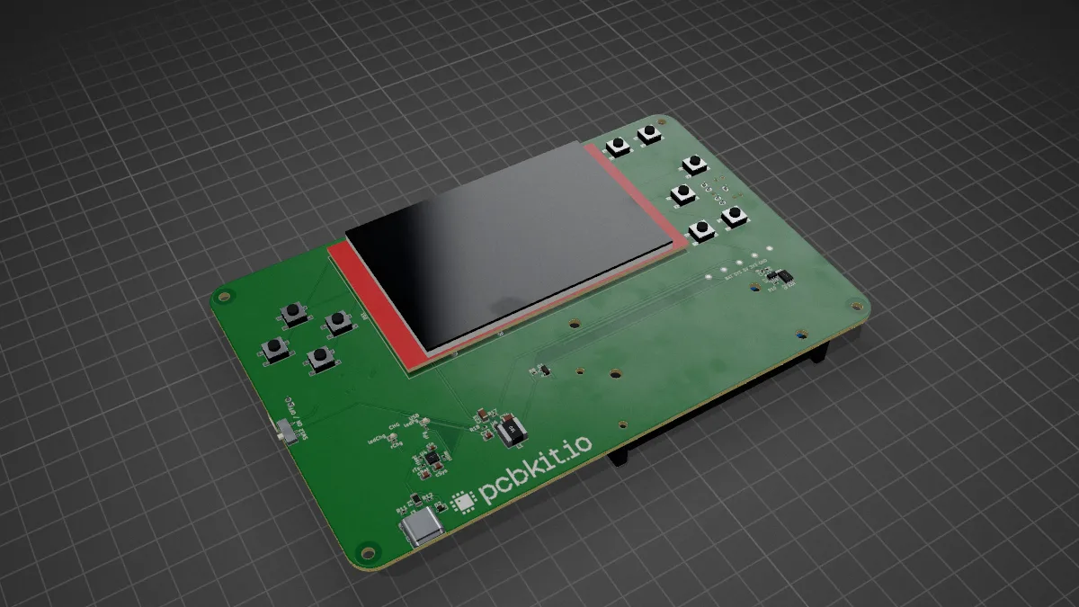 Play in your browser
The most capable variant: a Teensy 4.1 (i.MX RT1062, Cortex-M7 at 600 MHz) behind a 3.5″ 320 × 480 touch screen, the WAD in its 8 MB flash, ten buttons, audio to headphones and a speaker, two 18650 cells.
Ready to order90 parts4 layersGPL-2.0
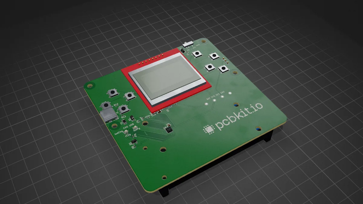 Play in your browser
The cheapest chip that runs Doom, by emulation: a CH32V003 with 2 KB of RAM interprets a larger RISC-V computer whose program boots from a 16 MB SPI flash and runs in an 8 MB SPI PSRAM, on a Nokia 5110 screen.
Ready to order69 parts2 layersGPL-2.0
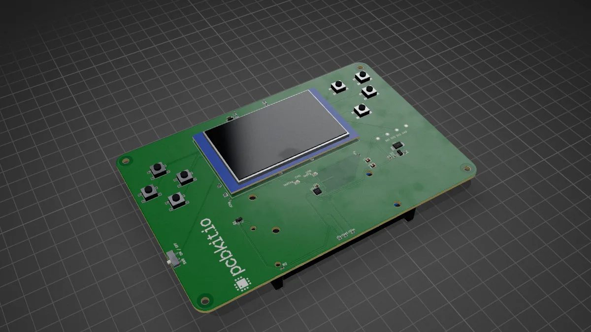 Play in your browser
A through-hole Doom kit: a Raspberry Pi Pico on sockets behind a 2.42″ 128 × 64 OLED, the shareware game compressed into its 2 MB flash (rp2040-doom), each frame dithered to one bit, eight buttons, two 18650 cells.
Ready to order45 parts2 layersGPL-2.0
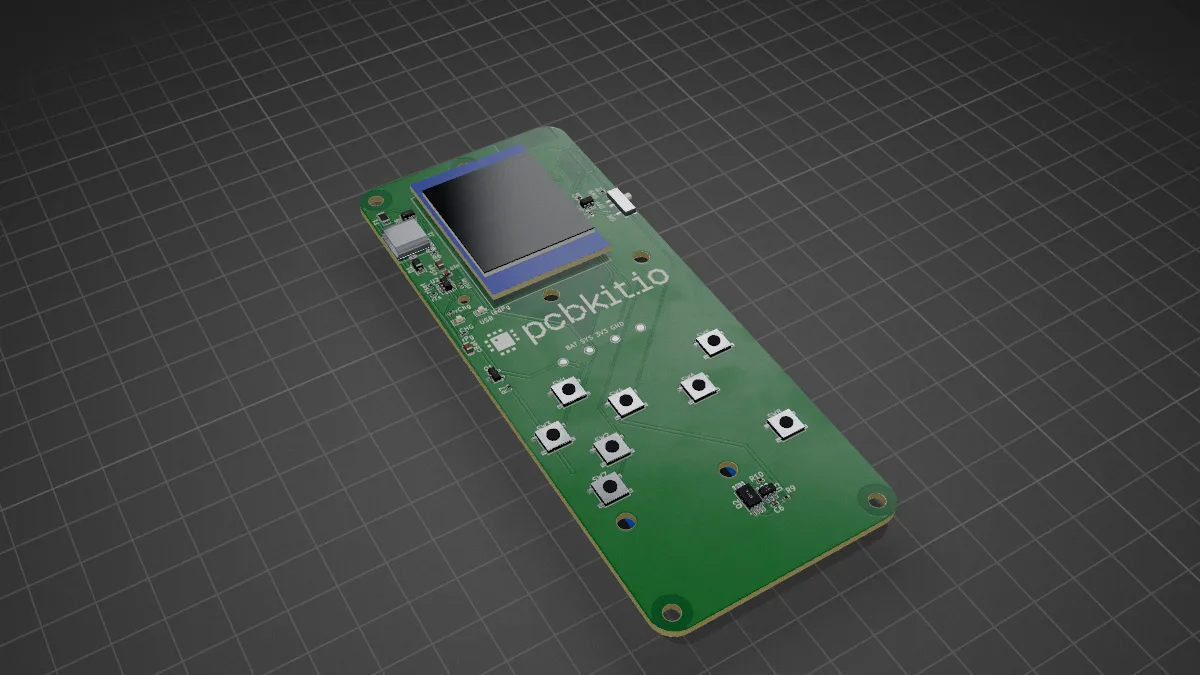 Play in your browser
A Game Boy-shaped Doom handheld on an ESP32-C3 module (RISC-V, 400 KB of SRAM, no PSRAM): the shareware game read in place from its 4 MB flash, a 1.3″ 240 × 240 IPS screen, eight buttons, two 18650 cells charged from USB-C.
Ready to order60 parts2 layersGPL-2.0
 Play in your browser
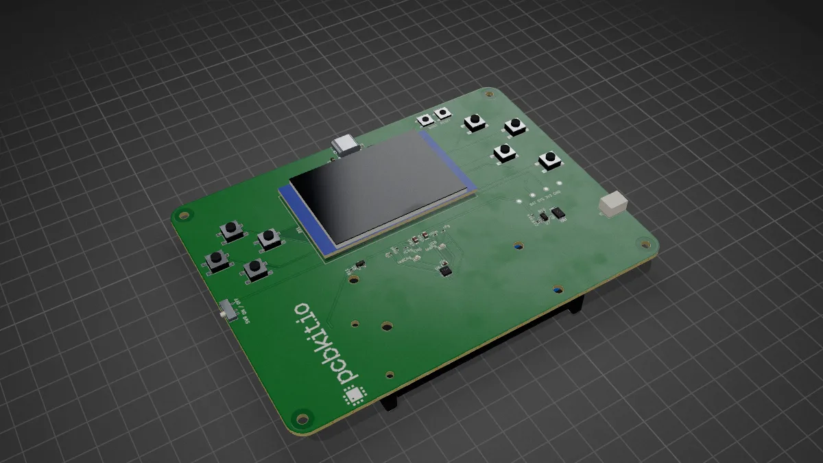
The Black Pill's STM32F411 (Cortex-M4F, 128 KB of SRAM) with an 8 MB SPI PSRAM and a 16 MB SPI flash: it runs a RISC-V computer built from the serial chips, through a cache, on a 2.0″ IPS.
Ready to order81 parts4 layersGPL-2.0
 Play in your browser
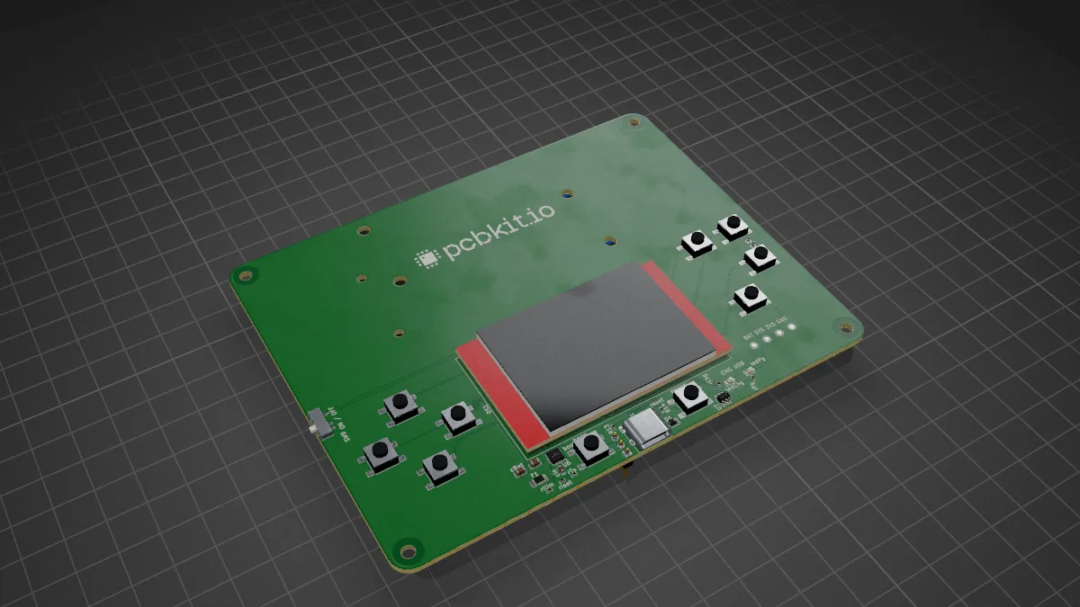
The RP2040 chip without a module: Raspberry Pi's minimal design with a 16 MB flash, the shareware game in it, a 1.8″ colour TFT, eight buttons, two 18650 cells charged from USB-C, on four layers.
Ready to order94 parts4 layersGPL-2.0
 Play in your browser
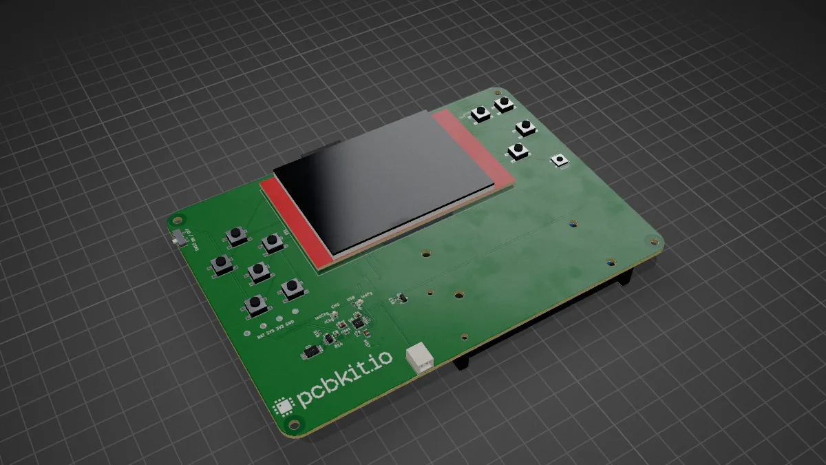
The classic ESP32 Doom: an ESP32-S3 module with 16 MB of flash and 8 MB of octal PSRAM under a 2.8″ ILI9341 touch screen, the WAD in flash and the heap in PSRAM, ten buttons, two 18650 cells.
Ready to order77 parts4 layersGPL-2.0
 Play in your browser
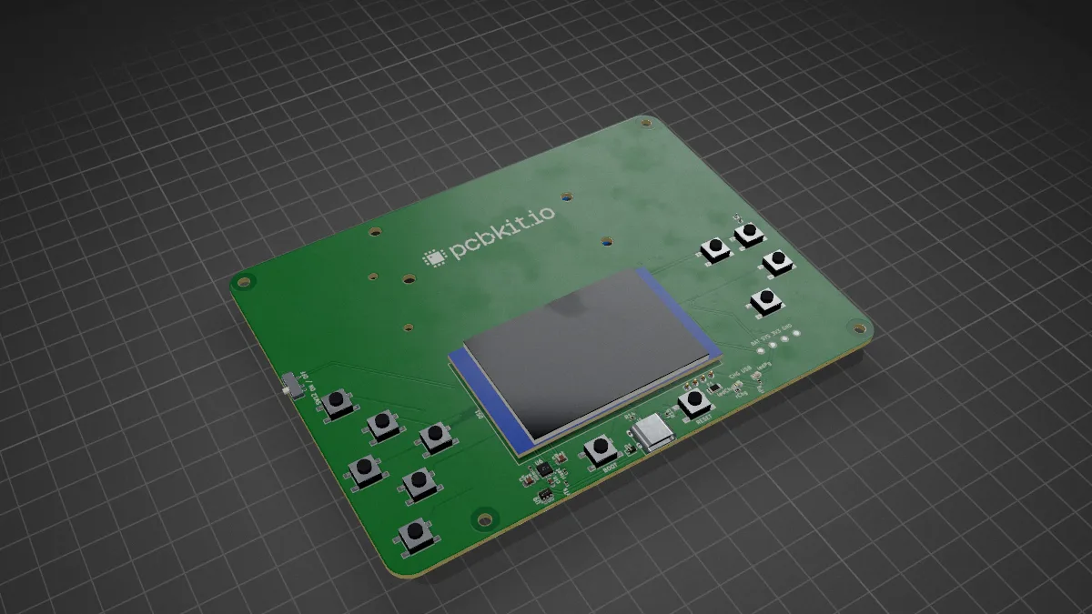
The RP2350A without a module: QSPI flash and an 8 MB PSRAM on one bus, both mapped through the XIP cache, a 2.0″ IPS, microSD, an I2S amplifier and a fuel gauge on four layers.
Ready to order102 parts4 layersGPL-2.0
 Play in your browser
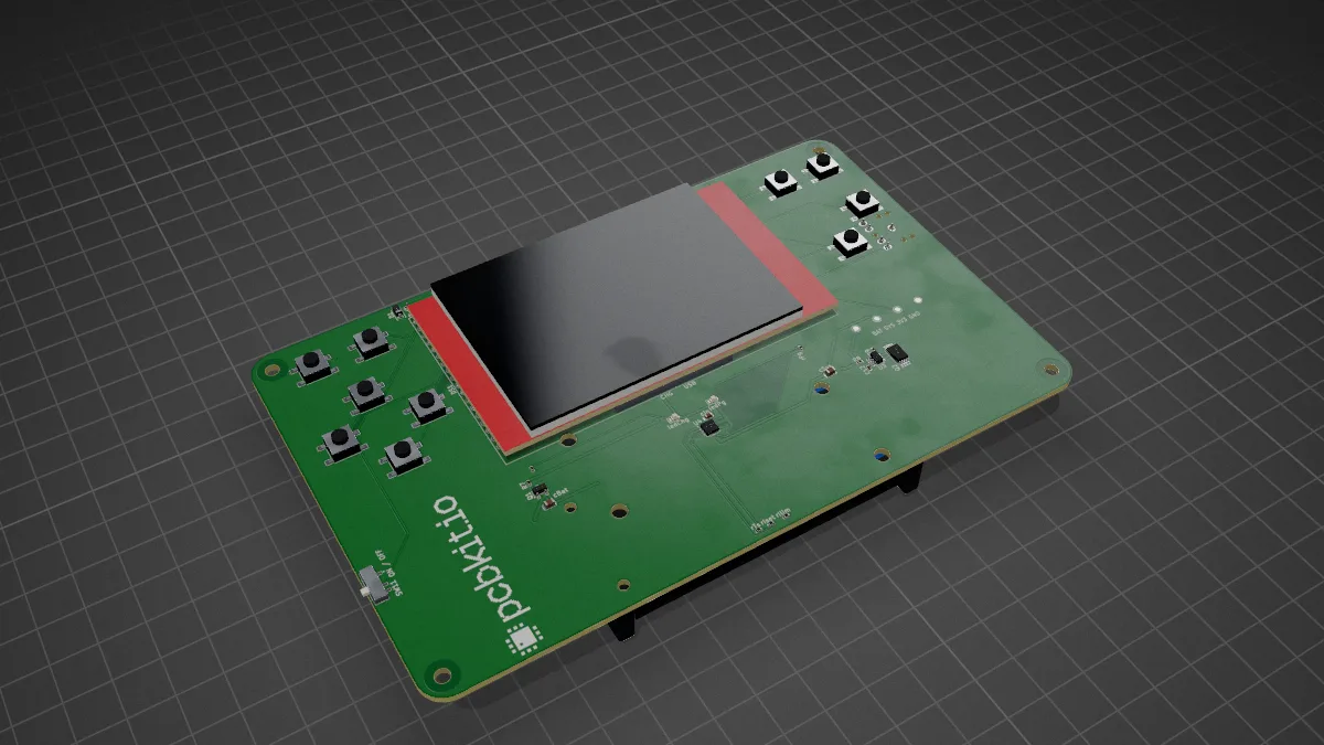
The reference device made orderable: a carrier for the Pimoroni Pico Plus 2 (RP2350, 16 MB flash, 8 MB PSRAM) with a 2.8″ ILI9341 touch screen, ten buttons and a headphone DAC.
Ready to order64 parts2 layersGPL-2.0
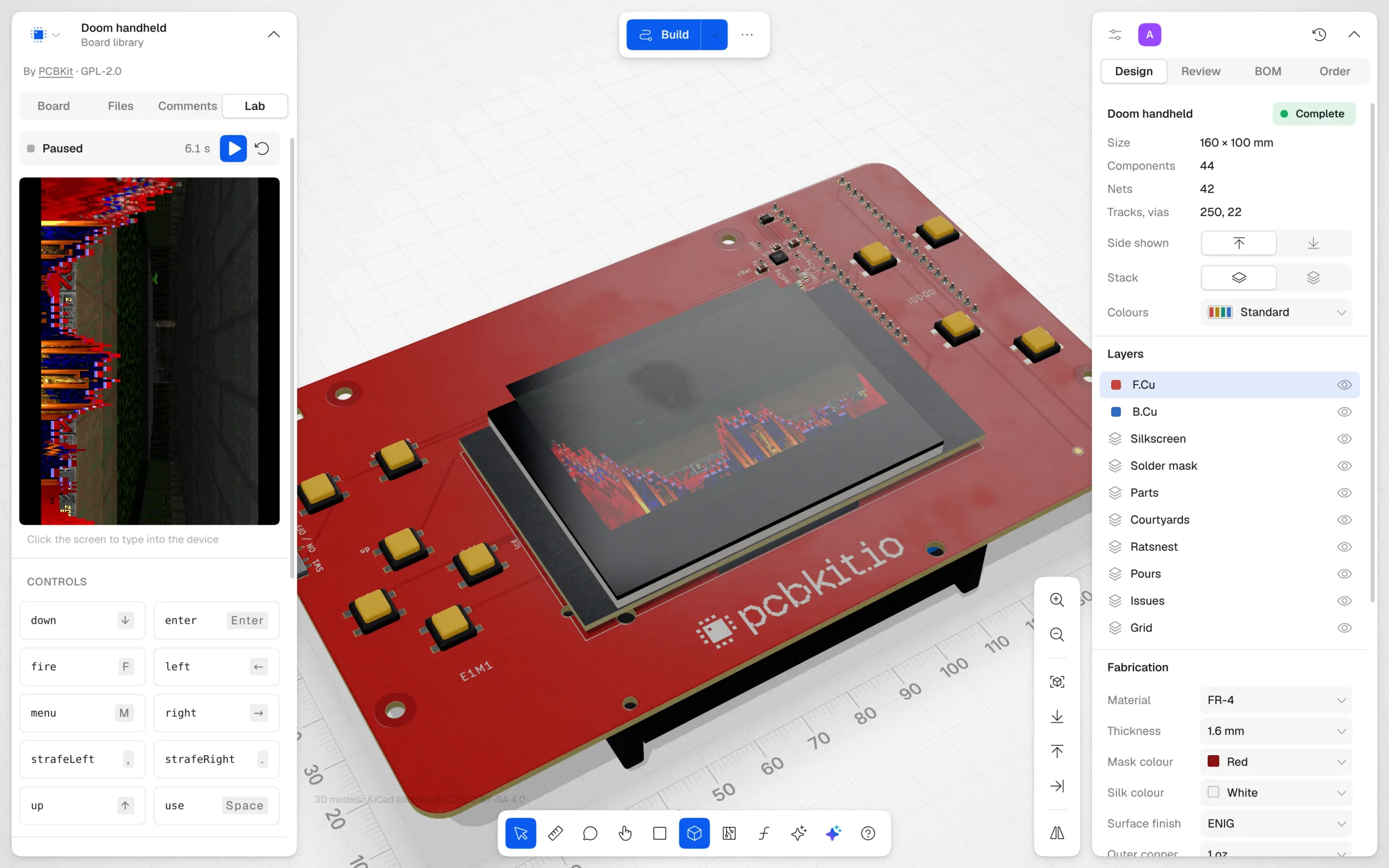
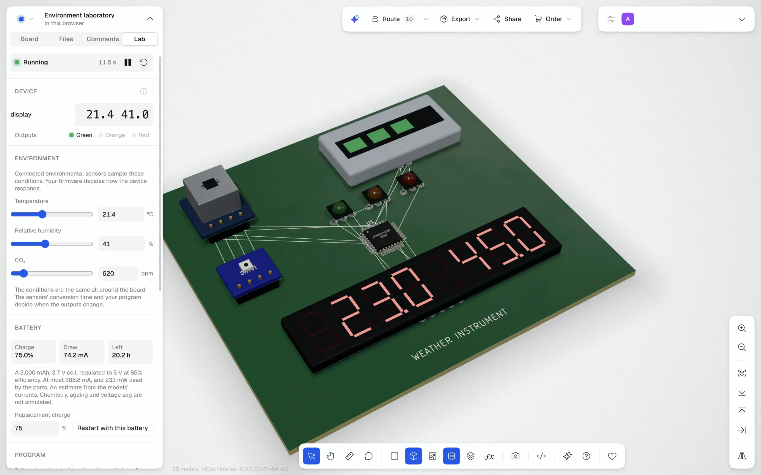
Real sketches with the libraries everyone uses, built exactly as the Arduino IDE builds them and running on a whole simulated ATmega328P beside the board in 3D. Then order the board and flash the same sketch onto it.
Sensors are timed digital models, not analog physics. Anything a model does not cover stops with a message instead of a guess.
 Ready to orderWeather stationAn Arduino Nano reads an SHT31 and shows the temperature and humidity large on an OLED, with the dew point and how the air feels, the day's lowest and highest and a graph of the last two minutes.
 Ready to orderCO₂ monitorSensirion's SCD40 measures CO₂, temperature and humidity every five seconds; the OLED shows the concentration with a ten-minute graph and a traffic light says when to open a window.
 Ready to orderThermostatA room thermostat that turns a radiator valve: a PI controller opens a servo as far as an SHT31 finds the room below the setpoint, the red light shows heating, − and + set the target and the EEPROM keeps it.
 Ready to orderLCD runnerThe classic 16 × 2 character LCD on LiquidCrystal's wiring: a dinosaur made of custom characters runs along the bottom line, jumps cacti with the button and runs under birds; turn the trimmer and the contrast changes as on the real module.
 Ready to orderEgg catcherThe 1980s pocket game on a battery: eggs roll down four chutes and the catcher's basket goes where you press, Q and A on the left, P and L on the right; three broken eggs end it.
 Ready to orderSnakeSnake on the pocket console, an Arduino Nano behind a 0.96" OLED with a D-pad and two buttons: steer with the arrow keys, eat, grow and go faster; the best score stays in the EEPROM.
 Ready to orderPongPong on the pocket console: you on the left with up and down, the computer on the right; the ball speeds up with every return and leaves the paddle at an angle.
 Ready to orderFlappy birdA flappy bird on the pocket console: X flaps, gravity does the rest, pipes scroll in with a gap to fly through; one point a pipe and the best kept in the EEPROM.
 Ready to orderBreakoutBreakout on the pocket console: move the paddle with left and right, serve with X; five rows of bricks, three balls, the angle off the paddle set by where the ball lands.
 Ready to orderFalling blocksFalling blocks on the pocket console: a 10 × 20 well beside the next piece and the score; left and right move, X turns, down drops faster, Z drops at once; full lines clear and the pace rises.
 Ready to orderDiceDice on the pocket console: X rolls one to five dice that tumble before they settle, up and down choose how many, Z shows how often each sum came up.
 Ready to orderSimonSimon on a round board: four coloured lights, each with its button; the Nano plays a sequence and you repeat it, one more every round, a little faster.
 Ready to orderMagic drawing screenTwo knobs draw on an OLED, one across and one up and down, as on the toy; the button wipes the picture.
AVR and Arduino
avr-gcc 15.2.0 with ArduinoCore-avr 1.8.8, fourteen libraries and Arduino’s preprocessing, built to WebAssembly from pinned sources; a rebuild reproduces the tools byte for byte.
ATmega328P, ATmega168P
Clang and LLD 19
RISC-V and Arm Cortex-M from one compiler, with a kit per chip: start-up code, link layout and register headers.
RP2040, RP2350, STM32F103, F401, F411, G030, G431, CH32V003, ESP32-C3, i.MX RT1062
Espressif Clang
Espressif’s LLVM for the Xtensa cores, compiled to WebAssembly, with ESP-IDF’s register headers and low-level drivers.
ESP32, ESP32-S3
Analysis and simulation
Ask the board in plain words. Your agent writes the analysis, PCBKit solves the physics of the copper you actually routed, draws the answer on the board and says plainly what it could not know.
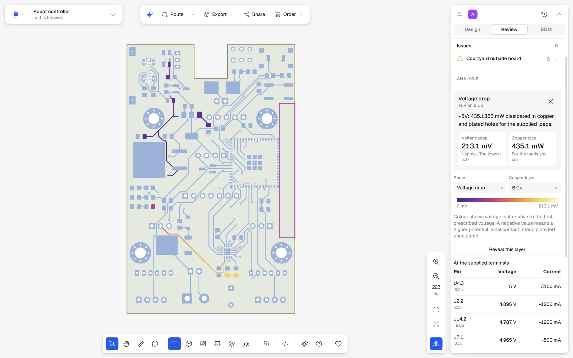
Voltage drop
Every track, via and pour of the robot controller’s 5 V rail meshed and solved: 3.1 A to two servo headers, 215 mV lost on the way, 437 mW of heat in the copper.
Heat
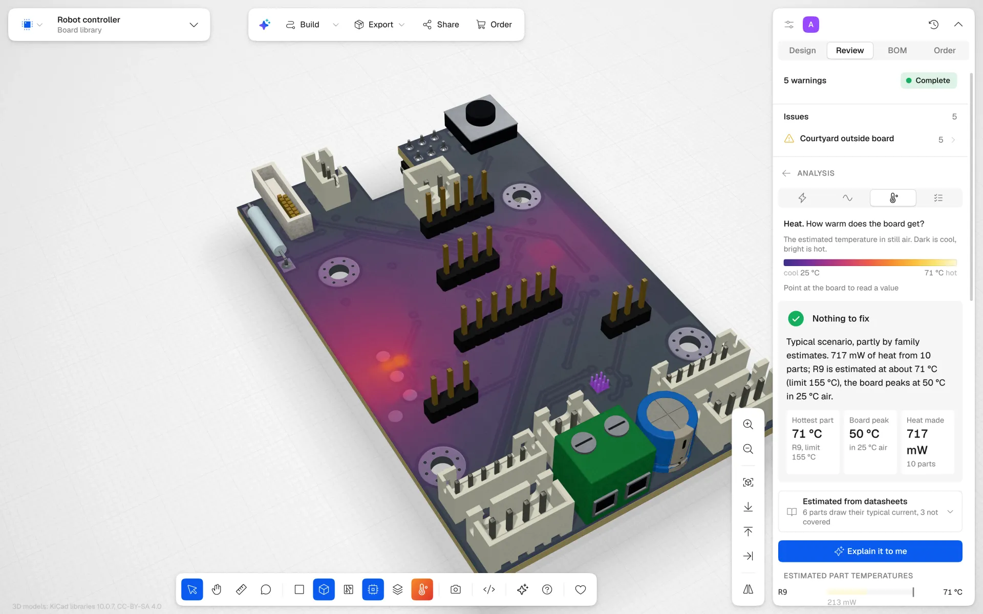
The board’s temperature in still air from what each part sheds. On the robot controller R9 runs at about 71 °C against its 155 °C limit; the board peaks at 50 °C.
Power
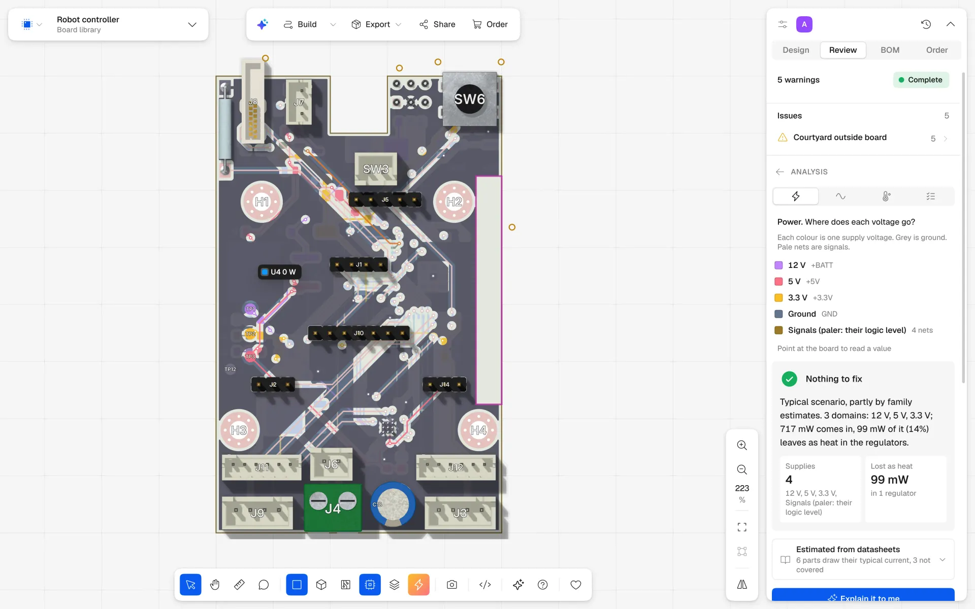
Every rail coloured on the copper, from the inputs through the regulators to the loads: 717 mW comes in, 99 mW of it leaves as heat in the regulator.
Current
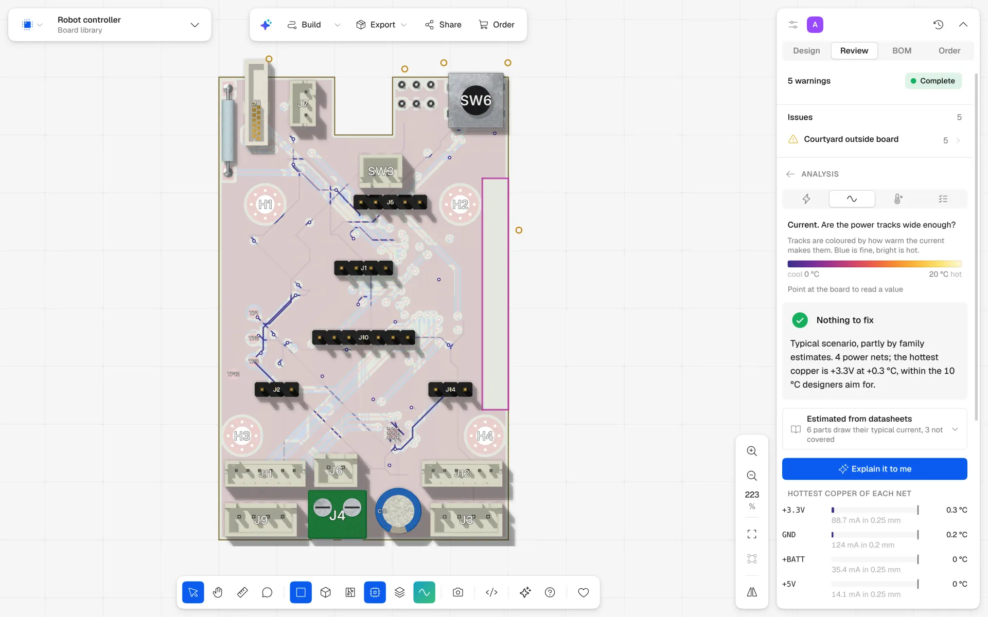
Each power track coloured by how much its current warms it. On the robot controller the hottest, +3.3V, rises 0.3 °C, well within the 10 °C designers aim for.
Signal integrity
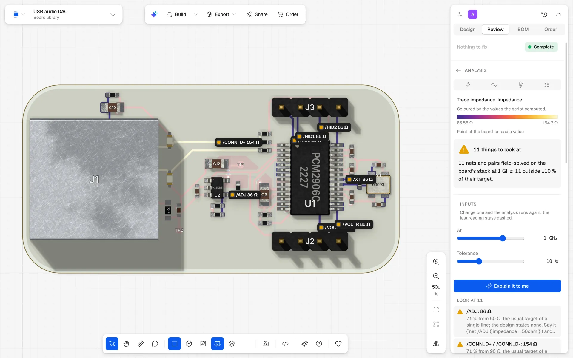
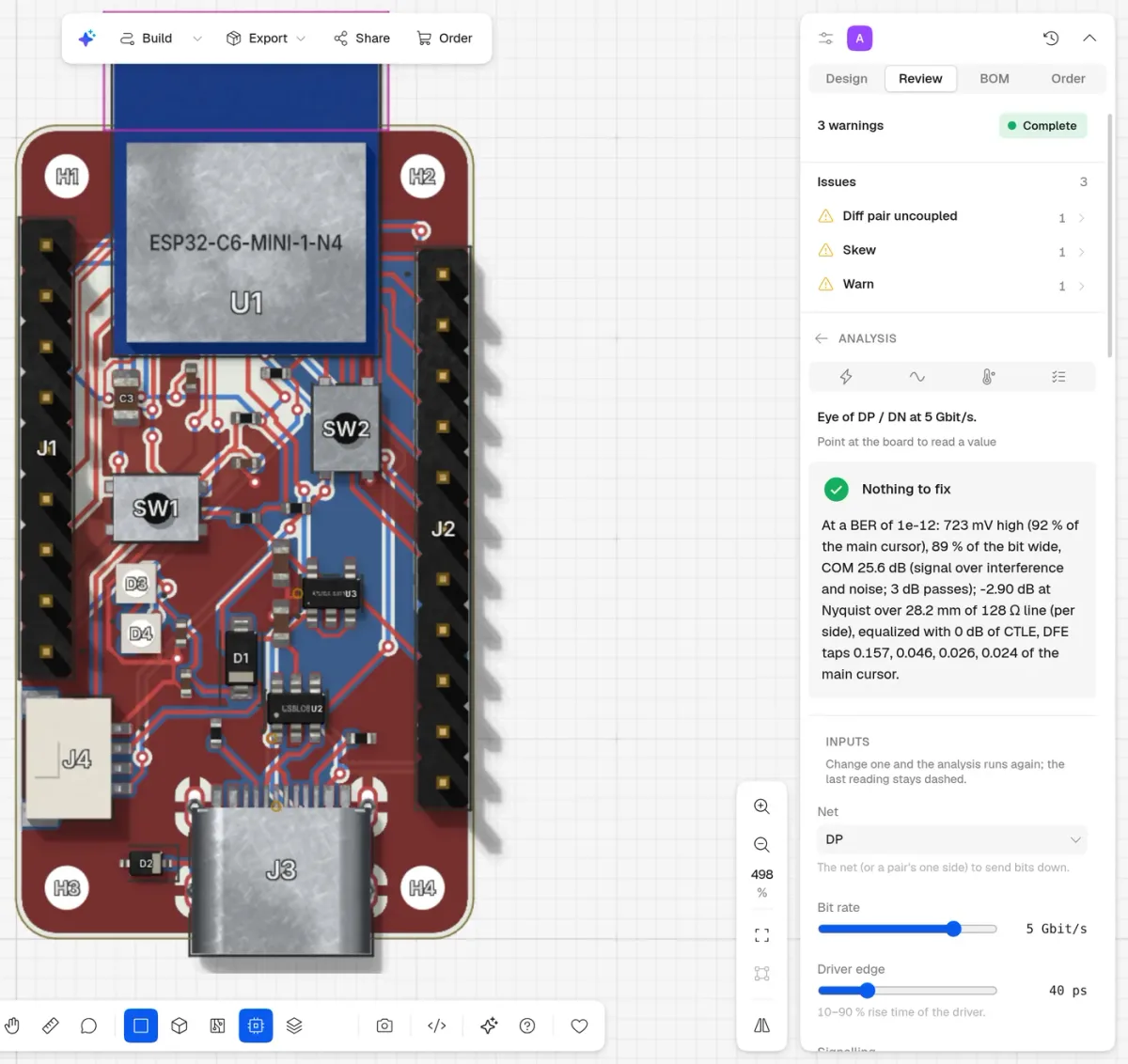
Every net and pair field-solved on the board’s own stack. The USB DAC’s data pair reads 154 Ω where USB wants 90 Ω, and the finding says what to change.
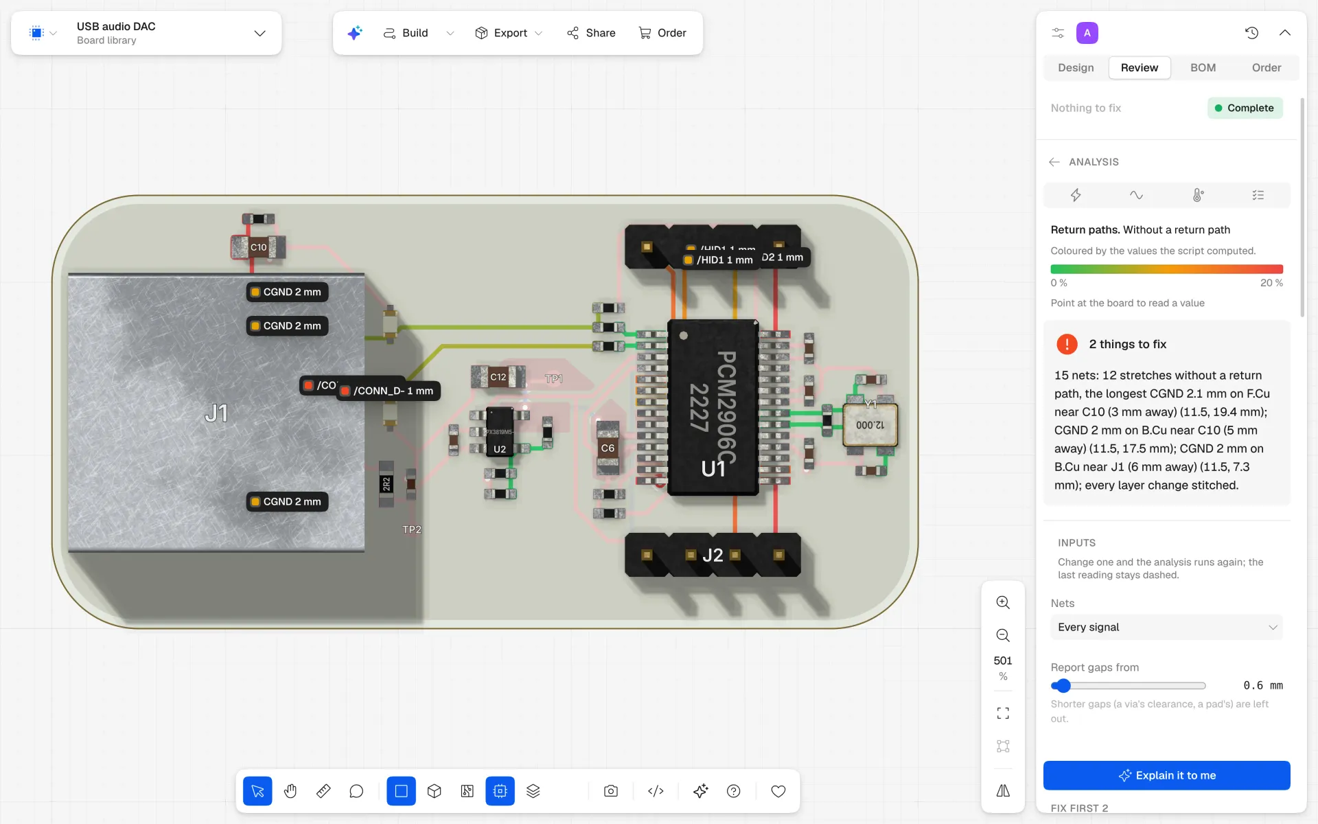
Return paths
Copper with no plane under it, marked where it runs: on the USB DAC twelve short stretches, the longest 2.1 mm, and every change of layer stitched.
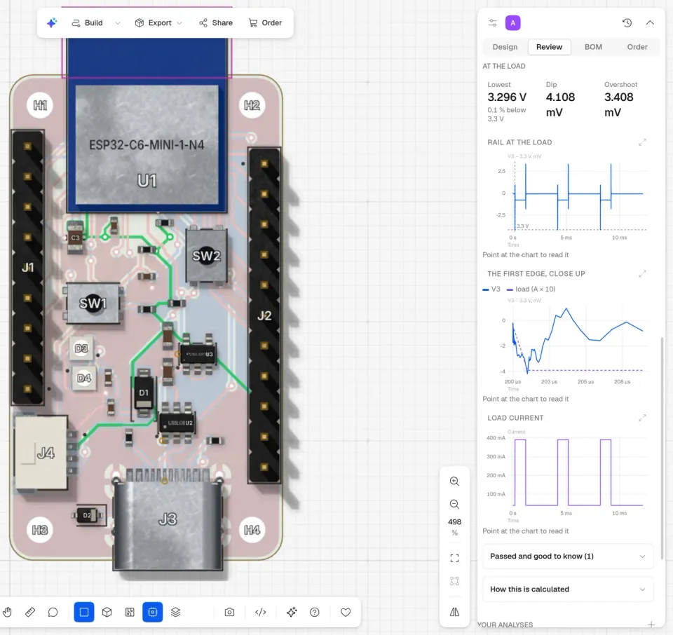
Power integrity
A load step through the board’s own regulator, capacitors and copper: 390 mA bursts on an ESP32-C6 board’s 3.3 V rail dip it by 4.1 mV.
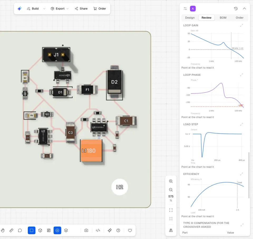
Converters
Loop gain and phase, a load step and the efficiency over load, from the converter’s own parts on the board, with the compensation it asked for.
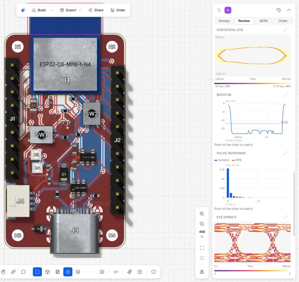
High speed
The channel from the copper as routed, equalized as a SerDes would train it: the statistical eye, the bathtub, the pulse response and a PRBS eye.
A short script in a sandbox reads the board, calls PCBKit’s solvers and draws the answer on it: findings in place, curves, heat maps and colour over the copper in 2D and 3D.
Operating points, sweeps, AC, noise and transients with SPICE netlists and IBIS buffers. Lossy lines with skin effect, eyes with equalization.
Circuits within 1 µV of ngspice, impedance within 0.7 % of Hammerstad–Jensen, lossy lines within 0.2 dB of the exact solution to 5 GHz. A model PCBKit lacks is reported as missing, never filled in.
Pre-compliance, not sign-off: there is no 3D full-wave solver, emission from cables is not modelled and IBIS-AMI models are not run. Every script says what it assumed.
The language
A board is one short text file, design.pcbkit, beside the KiCad files: what is on the board, how it is connected and what it is for, with real units. Your agent writes it, you can read it, git keeps every version and PCBKit works out where the copper goes.
pcbkit 2

// A USB-C sensor board: 3.3 V from USB, a serial bridge and the console header a 3.3 V FTDI
// cable plugs into, an I2C humidity sensor with its decoupling and pull-ups, a power LED.
net VBUS {
  voltage = 5V
  current = 500mA
}
net V3V3 { voltage = 3.3V }
net GND, DP, DN, TX, RX, SDA, SCL

board = Board { name = "usb-sensor" }

usb = UsbC2 {
  vbus -- VBUS
  gnd -- GND
  dp -- DP
  dn -- DN
}
ldo = Ldo {
  vin -- VBUS
  vout -- V3V3
  gnd -- GND
  current = 100mA
}
bridge = UsbUart {
  dp -- DP
  dn -- DN
  vcc -- V3V3
  gnd -- GND
  tx -- TX
  rx -- RX
}
console = UartHeader {
  tx -- TX
  rx -- RX
  vcc -- V3V3
  gnd -- GND
}

/// A humidity sensor in SOIC-8, its pins typed: a supply above 3.6 V does not compile.
part Sensor: Part {
  footprint = soic(8)
  pinout = {
    VDD = "8"
    GND = "4"
    SDA = "5"
    SCL = "6"
    ADDR = "1"
    NC1 = "2"
    NC2 = "3"
    INT = "7"
  }
  pinTypes = {
    VDD = io.powerIn(min = 1.7V, max = 3.6V)
    GND = .ground
    SDA = io.openDrain(max = 3.6V)
    SCL = io.input(max = 3.6V)
    ADDR = io.input(max = 3.6V)
    NC1 = .nc
    NC2 = .nc
    INT = .openDrain
  }
}
U2 = Sensor {
  VDD -- V3V3
  GND -- GND
  SDA -- SDA
  SCL -- SCL
  ADDR -- GND
  INT -- .nc
}
C1 = cap(100nF) { decouples = U2.VDD }
i2c = I2cPullups {
  sda -- SDA
  scl -- SCL
  vcc -- V3V3
  speed = 400kHz
  capacitance = 50pF
}
power = LedIndicator {
  signal -- V3V3
  gnd -- GND
  color = .green
  current = 1mA
}
Ordering
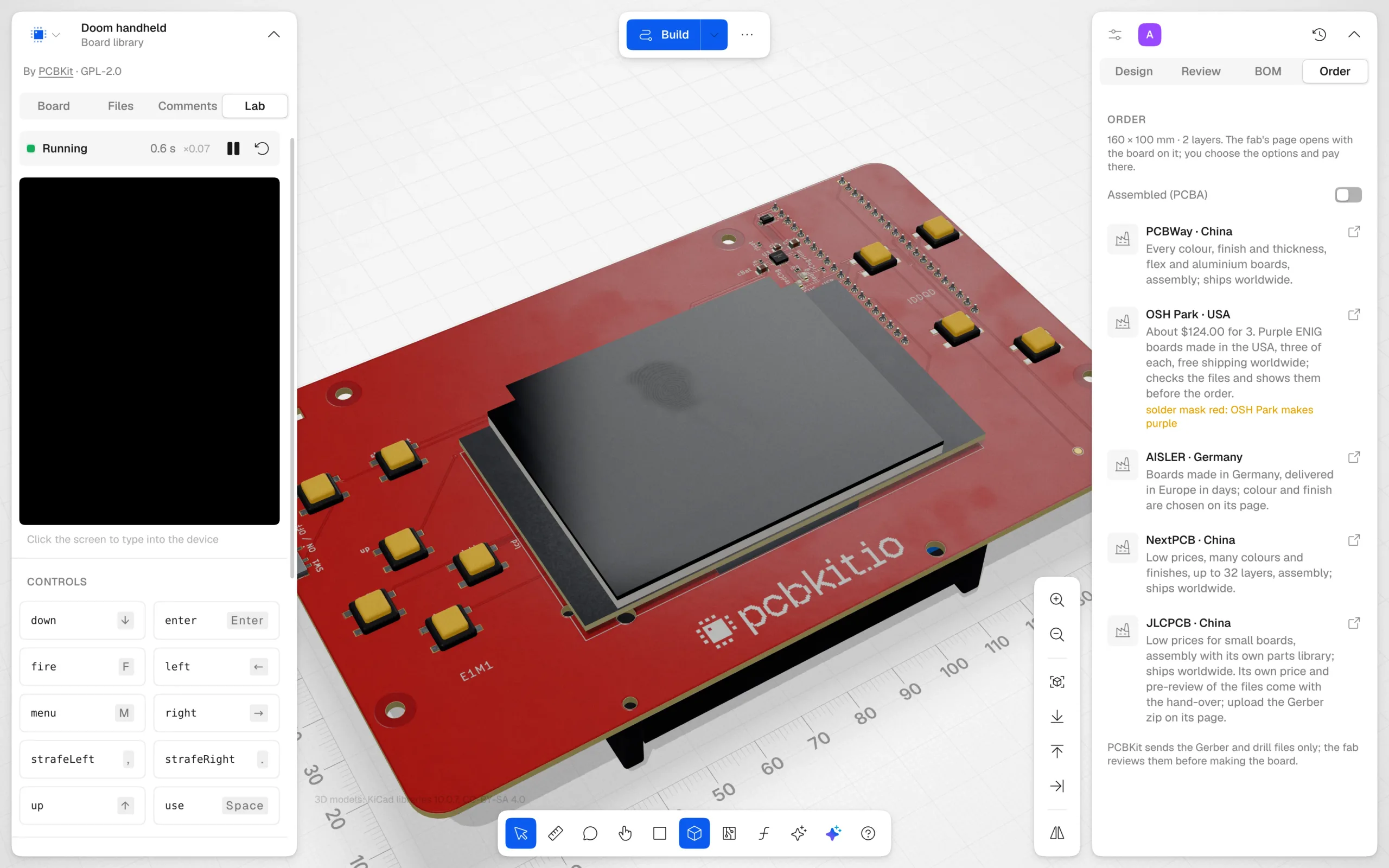
Gerber and drill files, the parts list and the placement file, zipped the way factories ask for them. Pick PCBWay, OSH Park, AISLER, NextPCB or JLCPCB and the board lands on the fab’s own order page, its colour and finish checked against what that fab makes. You choose the options and pay there.
The archive is frozen by its digest with what it orders and read back before it goes: the order record.
The library
8,500+ open boards by the people who made them: keyboards, radios, synths, sound cards, watches. Each opens with its AI tour, keeps its author and its licence and can be changed and routed again.
Audio
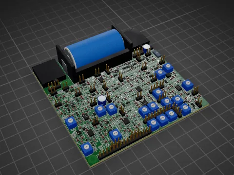
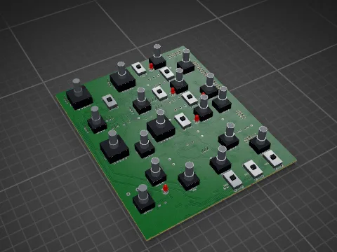
10x10 cm practice board full of 0805 parts, SOT-23 transistors and SOIC-8 opamps forming 23 guitar pedals.
GPL-3.0
Audio
Main VCO board of an analog monosynth with SSI2130 VCOs, SSI2140 VCF and digital control.
CC-BY-4.0
Retro computing
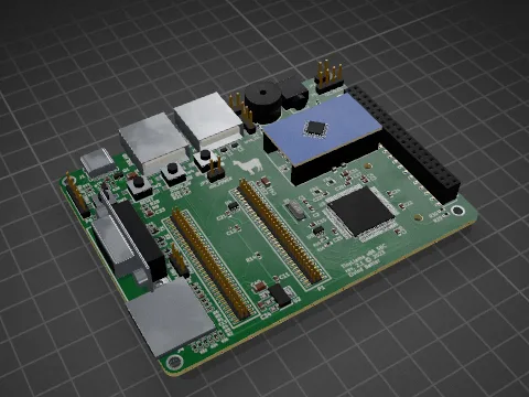
A tiny x86 retro computer
GPL-3.0
Keyboard
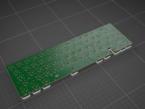
Minimalist 65% custom keyboard with VIA support, inspired by bakeneko65.
MIT
Open hardware
MIT
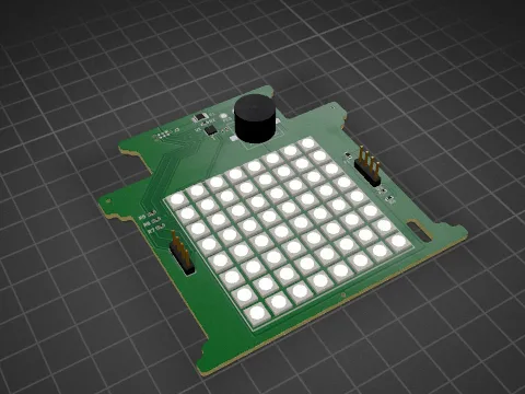
Audio
Ch32 based christmas card with 8x8 screen, sound and capacitive buttons
MIT
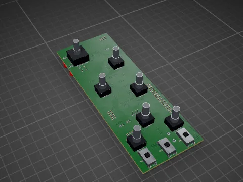
Audio
Analog signal board of a monosynth with an SSI2140 filter and SSI2164 VCA, TL072 op-amps and a voltage reference.
CC-BY-4.0
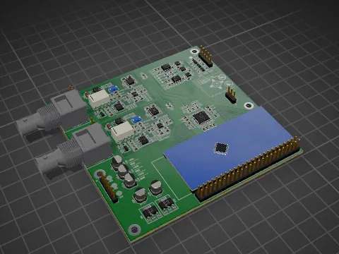
Sensors
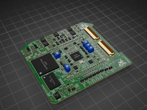
Analog front-end board of a 2-channel, ~20 MHz oscilloscope DAQ that feeds a Tang Nano 9K FPGA, with an RPi Pico for control.
GPL-3.0
Browse the librarySources and licences
CLI and CI
Route, check, render and export your KiCad project where it is (Altium, Eagle and EasyEDA boards import), offline, answering in JSON for scripts and agents and serving the same commands over MCP to any local agent. macOS, Linux and Windows; release 2026.10.31.
curl -fsSL https://pcbkit.io/install.sh | shPCBKit’s check on every push and before every order, on any KiCad repository: a verdict in levels, a report anyone can re-run digest for digest and waivers kept with their reasons. GitHub Actions and GitLab CI.
uses: pcbkit-io/verify@v0