
2 layers65 × 56 mm
AI4R PIHAT
pranavpai/Autonomous-RC-Car-AI-Project
Autonomous RC car with cone-based lane keeping, ToF obstacle avoidance, and software-in-the-loop simulation using ROS2
15 parts2MIT

 pranavpai/Autonomous-RC-Car-AI-Project2
Autonomous RC car with cone-based lane keeping, ToF obstacle avoidance, and software-in-the-loop simulation using ROS2
AI4R SENSORPCB is an open-source printed circuit board by pranavpai, from the pranavpai/Autonomous-RC-Car-AI-Project repository on GitHub, published under the MIT licence. It is a 2-layer board of 50 × 80 mm with 25 parts on 67 nets, routed with 304 tracks and 52 vias.
It is built around the FSM300, LD1117V33C and RP2040-ZERO. Its parts include 10 connectors, 3 ICs, 2 capacitors, 2 resistors and 1 transistor. It belongs with the sensors and measurement and robots and motor control boards and the RP2040 boards of this library.






A complete autonomous driving stack for RC-scale vehicles featuring real-time cone-based lane keeping, ToF-based obstacle avoidance, and a comprehensive software-in-the-loop simulation environment.
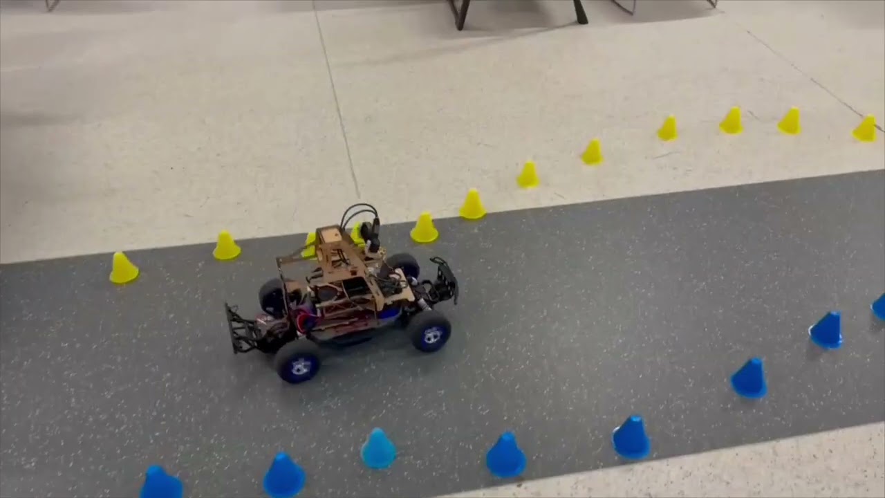
Click the image above to watch the RC car navigating different scenarios
This project implements a complete autonomous driving system for a Traxxas RC car platform, developed as part of the AI for Robotics (ELEN90095) course. The system combines:
The vehicle successfully navigates cone-defined tracks while dynamically avoiding obstacles, demonstrating the integration of computer vision, sensor fusion, and real-time control.
| Feature | Description |
|---|---|
| Cone-Based Lane Keeping | Linear regression on detected yellow/blue cones with proportional steering control |
| Obstacle Avoidance | Multi-zone ToF sensing with velocity-aware PD controller and emergency braking |
| Gap Navigation | Intelligent maneuvering around obstacles when sufficient clearance exists |
| Sensor Fusion | Integration of camera, ToF, IMU, LiDAR, and wheel encoder data |
| Simulation Environment | Complete SIL testing with realistic sensor noise models |
| Batch Testing | Automated regression testing across multiple track scenarios |
| Web Interface | Real-time monitoring and control via browser-based dashboard |
| Docker Deployment | Containerized environment for reproducible builds |
┌─────────────────────────────────────────────────────────────────────────┐
│                           PERCEPTION LAYER                               │
├─────────────────┬─────────────────┬─────────────────┬───────────────────┤
│   OAK-D Camera  │  VL53L5CX ToF   │   BNO08x IMU    │    RPLiDAR A1     │
│   (YOLOv8)      │   (4x4 Array)   │   (9-DOF)       │    (360°)         │
│   30 Hz         │   20 Hz         │   400 Hz        │    10 Hz          │
└────────┬────────┴────────┬────────┴────────┬────────┴─────────┬─────────┘
         │                 │                 │                   │
         ▼                 ▼                 ▼                   ▼
┌─────────────────────────────────────────────────────────────────────────┐
│                          ROS2 MESSAGE LAYER                              │
│  /cone_points    /tof_sensor    /imu_sensor    /scan    /wheel_speed    │
└─────────────────────────────────┬───────────────────────────────────────┘
                                  │
                                  ▼
┌─────────────────────────────────────────────────────────────────────────┐
│                           POLICY NODE                                    │
│  ┌─────────────────┐  ┌─────────────────┐  ┌─────────────────┐         │
│  │  Lane Keeping   │  │    Obstacle     │  │  Gap Navigation │         │
│  │  (Cone Fitting) │  │   Avoidance     │  │   (Maneuvering) │         │
│  │                 │  │   (PD Control)  │  │                 │         │
│  └────────┬────────┘  └────────┬────────┘  └────────┬────────┘         │
│           └────────────────────┼────────────────────┘                   │
│ ▼ │| Component | Role |
|---|---|
| Raspberry Pi 4 | Main compute, ROS2 nodes |
| RP2040 Pico #1 | IMU interface (BNO08x) |
| RP2040 Pico #2 | Encoder & RC switch monitoring |
| Sensor | Model | Purpose | Key Specs |
|---|---|---|---|
| Camera | OAK-D | Cone detection (YOLOv8) | 120° FOV, 30 Hz, 0.5-10m range |
| ToF Array | VL53L5CX | Obstacle detection | 4×4 zones, 45° FOV, 20 Hz, ±5mm accuracy |
| IMU | BNO08x | Orientation & acceleration | 9-DOF, 400 Hz, auto-calibration |
| LiDAR | RPLiDAR A1 | Environment mapping | 360°, 10 Hz, 0.15-12m range |
| Encoder | Hall Effect | Speed estimation | 16.32 ticks/rev, period-based |
The lane-keeping system uses computer vision to detect yellow (left) and blue (right) cones, fitting linear trajectories to determine the road centerline.
# Simplified lane-keeping logic
if yellow_cones and blue_cones:
    centerline = (yellow_fit + blue_fit) / 2
elif yellow_cones:
    centerline = yellow_fit - ROAD_WIDTH/2
elif blue_cones:
    centerline = blue_fit + ROAD_WIDTH/2

lateral_error = evaluate_centerline(look_ahead_distance)
steering = -Kp * lateral_error
Key Parameters:
ROAD_WIDTH: 1000mmLOOK_AHEAD_DISTANCE: 1000mmKp_STEER: 80.0A velocity-aware PD controller monitors the ToF sensor array for obstacles, implementing graduated braking and emergency stop capabilities.
┌─────────────────────────────────────────────────────────┐
│                    ToF 4×4 Grid                         │
│  ┌───┬───┬───┬───┐                                      │
│  │ 0 │ 1 │ 2 │ 3 │  ← Zones 4-11 used for detection    │
│  ├───┼───┼───┼───┤                                      │
│  │ 4 │ 5 │ 6 │ 7 │  ← Center zones for forward sensing │
│  ├───┼───┼───┼───┤                                      │
│  │ 8 │ 9 │10 │11 │  ← Center zones for forward sensing │
│  ├───┼───┼───┼───┤                                      │
│  │12 │13 │14 │15 │                                      │
│  └───┴───┴───┴───┘                                      │
└─────────────────────────────────────────────────────────┘
Control Strategy:
Key Parameters:
BASE_TARGET_DISTANCE: 1.2mEMERGENCY_BRAKE_DISTANCE: 0.8mKp_OBSTACLE: 80.0Kd_OBSTACLE: 40.0When an obstacle is detected but sufficient clearance exists on one side, the system calculates navigable gaps and steers around the obstacle.
# Gap calculation
gap_on_left = |obstacle_y - yellow_cones_y| - obstacle_width/2
gap_on_right = |obstacle_y - blue_cones_y| - obstacle_width/2

if max(gap_on_left, gap_on_right) >= MIN_GAP_WIDTH:
    steer_toward_larger_gap()
else:
    apply_pd_braking()
Key Parameters:
MIN_GAP_WIDTH: 0.35mMANEUVER_DISTANCE_THRESHOLD: 1.6mSTEERING_BIAS_GAIN: 80.0The project includes a comprehensive Software-in-the-Loop (SIL) simulation environment that publishes identical ROS2 topics as the real hardware, enabling rapid policy development and testing.
| Scenario | Description |
|---|---|
simple_straight.yaml | Baseline straight track |
s_curve.yaml | Two connected curves (20m) |
s_curve_tight.yaml | Tighter radius curves |
obstacle_course.yaml | Multiple obstacles |
obstacle_goldilocks.yaml | Single obstacle at optimal detection distance |
obstacle_immediate_wall.yaml | Emergency braking test |
real_track_oct14.yaml | Real measured track layout |
# Single scenario test
ros2 launch ai4r_pkg quick_test.launch.py \
  scenario:=obstacle_goldilocks \
  real_time_factor:=5.0

# Batch testing
ros2 run ai4r_pkg batch_tester.py \
  test/scenarios/tracks/ \
  --filter "obstacle" \
  --timeout 120
Results are saved to sim_results/ including JSON logs, performance plots, and MP4 recordings.
git clone https://github.com/yourusername/Autonomous-RC-Car-AI-Project.git
cd Autonomous-RC-Car-AI-ProjectFollow the official ROS2 installation guide.
cd ros2_ws

# Source ROS2
source /opt/ros/humble/setup.bash

# Install dependencies
sudo rosdep init  # Only needed once
rosdep update
rosdep install -i --from-path src --rosdistro humble -y

# Build
colcon build

# Source the workspace
source install/setup.bashcd mcu_ws/build
cmake .. && make
# Outputs: ai4r-sensors-rp1.uf2, ai4r-sensors-rp2.uf2cd docker
docker-compose up -d
# Access web interface at http://localhost:8080For the sensor PCB parser node to work, grant read/write access to the serial ports:
echo 'KERNEL=="ttyACM0", MODE="0666"' | sudo tee /etc/udev/rules.d/ttyACM0.rules
echo 'KERNEL=="ttyACM1", MODE="0666"' | sudo tee /etc/udev/rules.d/ttyACM1.rules
sudo udevadm control --reload-rules
sudo udevadm triggerros2 launch ai4r_pkg ai4r_bringup_launch.py# Vehicle control only
ros2 launch ai4r_pkg traxxas_launch.py
# Sensors + cone detection
ros2 launch ai4r_pkg traxxas_imu_tof_cone_detector_launch.py
# Policy node only
ros2 launch ai4r_pkg policy_launch.py
# Camera streaming
ros2 launch ai4r_pkg camera_stream_launch.pyros2 run ai4r_pkg keyboard_teleop.py# List all topics
ros2 topic list
# View cone detections
ros2 topic echo /cone_points
# View ToF data
ros2 topic echo /tof_sensor_vl53l5cx
# Check topic frequency
ros2 topic hz /cone_pointsros2 bag record /cone_points /tof_sensor_vl53l5cx /imu_sensor /wheel_speed_m_per_secAutonomous-RC-Car-AI-Project/
├── ros2_ws/ # Main ROS2 workspace
│ └── src/
│ ├── ai4r_pkg/ # Core package
│ │ ├── scripts/ # Python nodes
│ │ │ ├── policy_node.py # Main control policy
│ │ │ ├── cone_detector_node.py
│ │ │ └── models/ # YOLOv8 models
│ │ ├── src/ # C++ nodes
│ │ ├── launch/ # Launch files
│ │ ├── config/ # Parameter files
│ │ ├── drivers/ # Hardware drivers
│ │ └── test/
│ │ ├── simulation/ # SIL framework
│ │ └── scenarios/ # Test tracks (YAML)
│ └── ai4r_interfaces/ # Custom messages
│
├── mcu_ws/ # RP2040 Pico firmware
│ ├── ai4r-sensors-rp1.cpp # IMU interface
│ ├── ai4r-sensors-rp2.cpp # Encoder/RC switch
│ └── [libraries]/ # BNO08x, VL53L5CX, servo
│
├── docker/ # Docker configuration
├── web_interface/ # Browser-based dashboardrosidl_default_generators not foundcd /path/to/repository
sudo chmod 777 -R .i2cdetect -y 1lsusb | grep Movidiuspip install depthaisudo usermod -aG video $USERContributions are welcome! Please follow these steps:
git checkout -b feature/amazing-feature)git commit -m 'Add amazing feature')git push origin feature/amazing-feature)This project is licensed under the MIT License - see the LICENSE.txt file for details.
Built with ROS2 and Python
| Qty | Value | Footprint | References |
|---|---|---|---|
| 4 | Conn_01x04 | Connector_JST:JST_SH_SM04B-SRSS-TB_1x04-1MP_P1.00mm_Horizontal | J2, J3, J4, J5 |
| 4 | MountingHole | MountingHole:MountingHole_3.2mm_M3_DIN965_Pad | H1, H2, H3, H4 |
| 2 | Conn_01x03 | Connector_PinHeader_2.54mm:PinHeader_1x03_P2.54mm_Vertical | J7, J9 |
| 2 | R | Resistor_SMD:R_0805_2012Metric | R1, R2 |
| 2 | RP2040-Zero | RP2040-Zero:RP2040-Zero | RP1, RP2 |
| 1 | 100nF | Capacitor_THT:CP_Radial_D4.0mm_P2.00mm | C2 |
| 1 | 10uF | Capacitor_THT:CP_Radial_D4.0mm_P2.00mm | C1 |
| 1 | 2N3904 | Package_TO_SOT_THT:TO-92_Inline | Q1 |
| 1 | Conn_01x10 | Connector_PinHeader_2.54mm:PinHeader_1x10_P2.54mm_Vertical | J8 |
| 1 | Conn_02x10_Odd_Even | Connector_PinHeader_2.54mm:PinHeader_2x10_P2.54mm_Vertical | J10 |
| 1 | Conn_02x11_Odd_Even | Connector_PinHeader_2.54mm:PinHeader_2x11_P2.54mm_Vertical | J6 |
| 1 | FSM300 | FSM300:FSM300 | U1 |
| 1 | LD1117V3.3 | Package_TO_SOT_THT:TO-220-3_Vertical | U3 |
| 1 | SolderJumper_2_Open | Jumper:SolderJumper-2_P1.3mm_Open_Pad1.0x1.5mm | JP1 |
| 1 | USB_B_Mini | Connector_USB:USB_Mini-B_Lumberg_2486_01_Horizontal | J11 |
| 1 | ~ | Polulu2801RCSwitch:2801RCSwitch | U2 |
pranavpai/Autonomous-RC-Car-AI-Project
Autonomous RC car with cone-based lane keeping, ToF obstacle avoidance, and software-in-the-loop simulation using ROS2

krups/RockSatX-GHOST-Hardware
Hardware files for the 2025 RockSat-X GHOST mission


voluta-coop/Open-KIoT
Voluta.coop ha desarrollado esta PCB para solucionar problemas socioambientales, poniendo la tecnología al servicio de las personas y el medio ambiente.


formulaslug/fs-3-schematics
Electrical Design Repository for fs-3 schematics and PCBs


MSTRocketDesignTeam/Liquid-Engine-Controller
Evolution of the RDT's Custom Liquid Engine Control Unit!

It measures 50 × 80 mm and has 2 copper layers, 1.6 mm thick.
25 parts, built around the FSM300, LD1117V33C and RP2040-ZERO. The full list of its parts is on this page, with links to each part's symbol and footprint where PCBKit's library has them.
From the pranavpai/Autonomous-RC-Car-AI-Project repository on GitHub, at the commit this page was made from: the board is pcb_files/AI4R-SENSORPCB/AI4R-SENSORPCB.kicad_pcb and its schematic pcb_files/AI4R-PIHAT/AI4R-PIHAT.kicad_sch. PCBKit opens the board in the browser, with nothing to install.
Its repository publishes it under the MIT licence: you may reuse it on that licence's terms (keep the author's notice, and for a copyleft licence share your changes alike).