2 layers122.2 × 122.8 mm
Dcpower
hnz1102/dcpower
DC Power Unit for Breadboard based on ESP32-S3 microcontroller and AP33772S USB Power Delivery (PD) Sink Controller.
115 parts1

 hnz1102/electricload5
Electric Load and Logger
Mosfetload is an open-source printed circuit board by hnz1102, from the hnz1102/electricload repository on GitHub. It is a 2-layer board of 185 × 98 mm with 96 parts on 75 nets, routed with 643 tracks and 271 vias.
It is built around the ESP32-S3-WROOM-1-N16R8, TSB611ILT and CH224K, with the LD1117S33TR(MS), SPX3819M5-L and 2N7002K among its other parts. Its parts include 28 resistors, 22 capacitors, 9 ICs, 5 connectors and 4 transistors. It belongs with the power and sensors and measurement boards and the ESP32 boards of this library.


Electric Load and Logger
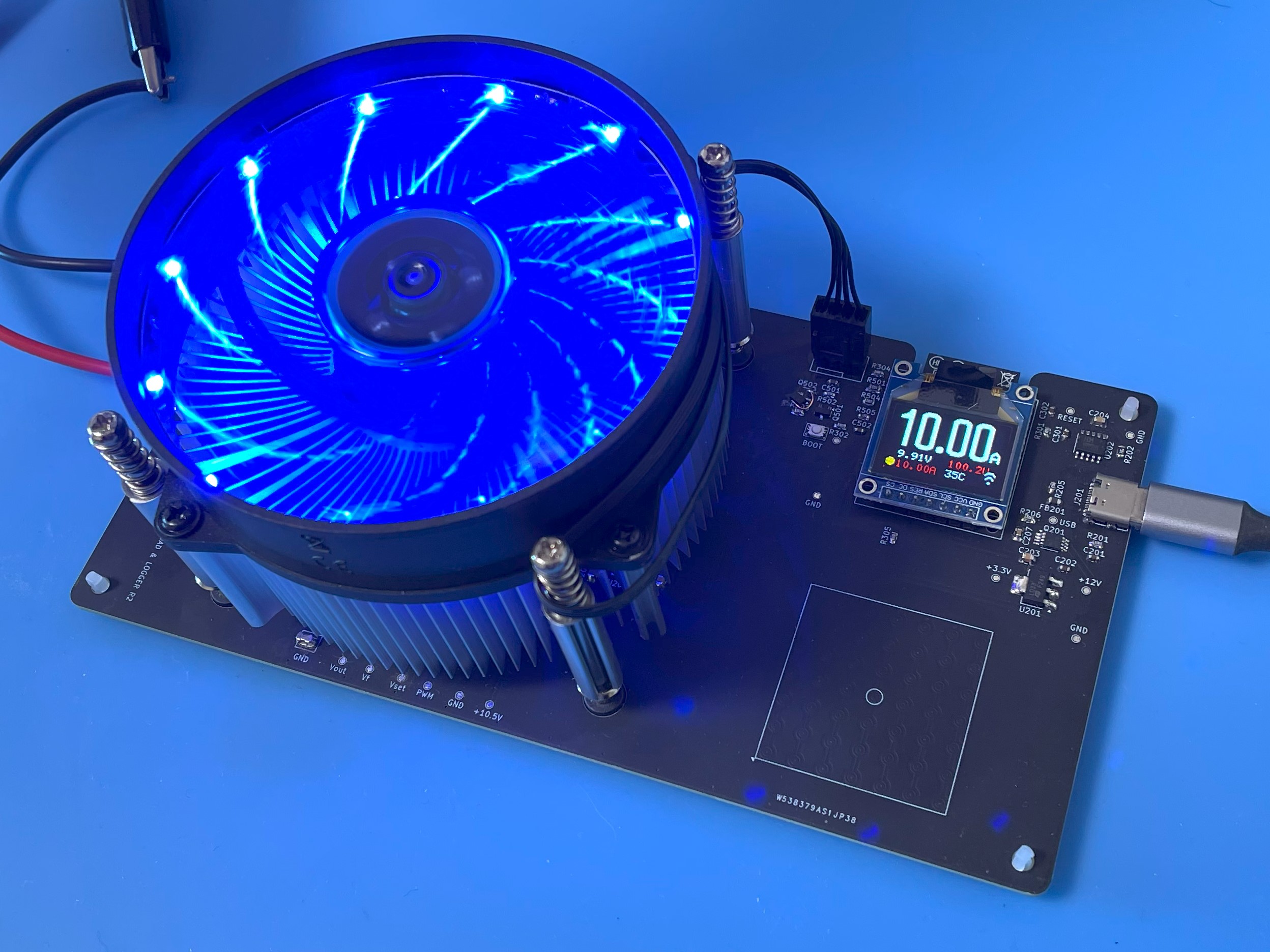
This is an Electric Load and Logger. It can consume the power of the device and send the data to the server. The maximum power is 100W, maximum voltage is 30V, and maximum current is 10A. But, it must be used under 100W. And it can measure the voltage, current, and power consumption of the device and send the data to the InfluxDB server. You can see the data on the Dashboard.
High Power - It can measure the power consumption of the device up to 100W.
Controllable - You can control the current consumption by the device. The current can be controlled every 10mA from 10mA to 10A.
Auto Control - The current consumption can be controlled automatically by the device using the PID controller.
High-resolution - By using Texas Instruments INA228 IC - 20-bit delta-sigma ADC, It can be got measurement data with 195.uV Bus voltage and 163.84mV Shunt voltage.
Microcontroller on board - No need for a client PC when you are measuring. Directly send to the server.
Transfer measurement data via WiFi - This Logger can transfer data to Linux PC via WiFi network and you can see the dashboard graph in influxDB.
Internal Memory Buffer - If the WiFi connection is not established, the data is stored in the internal memory buffer. When the WiFi connection is established, the data is sent to the server.
At first, connect the power supply to this electric load as shown in the image below. The Plus line is connected to the 'Input +' terminal, and the GND line is connected to the 'Input -' terminal. And Input- is connected to the GND terminal, and Input+ is connected to the 'VBUS' terminal. This allows the device to measure the voltage.
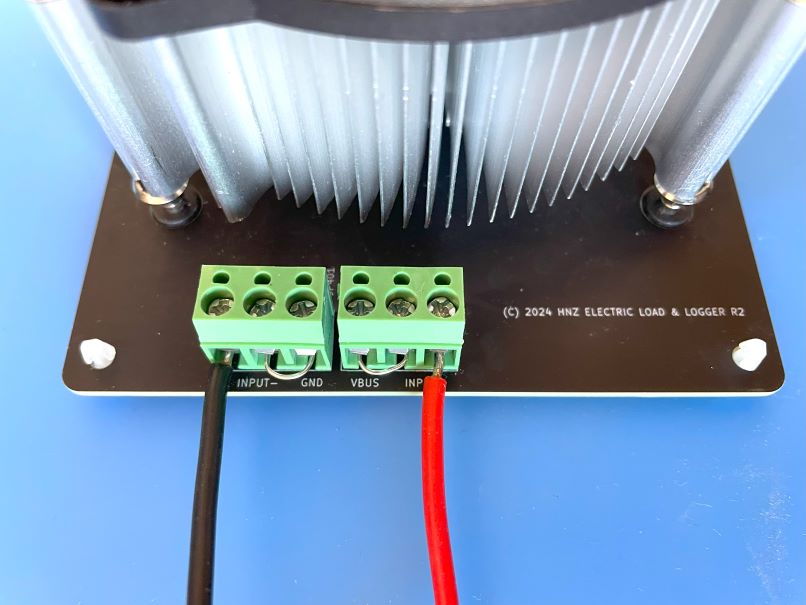
Then, connect the USB Power Delivery (PD) line to the USB-C port. The PD line must be connected to the USB PD Charger. This load gets power from the USB PD 12V.
After connecting the power supply, the display will show the current voltage, current, and power consumption. Then, you can set the current consumption by the device using the touch pad. Clockwise rotation increases the current, and counterclockwise rotation decreases the current. The current can be controlled every 10mA from 10mA to 10A. Fast rotation will increase or decrease the current quickly every 100mA. After setting the current, press the Center Position of the touch pad during over a second to start the load and measurement. The current consumption can be controlled automatically by the device using the PID controller.
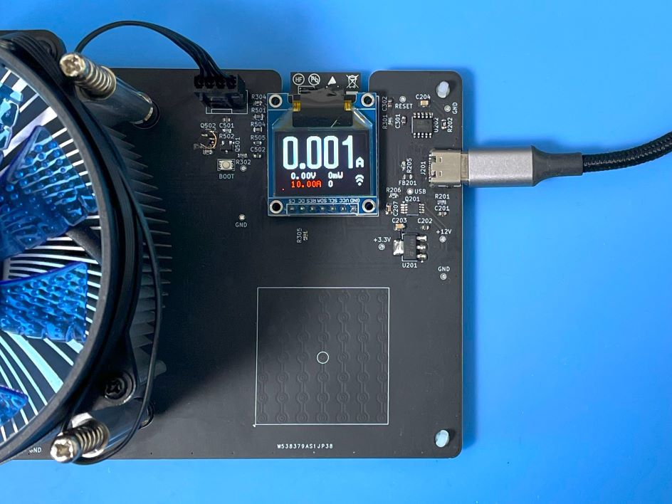
The display shows the current, voltage, power consumption, target current, temperature, PWM duty and status of the load. If you start the load, the display shows the yellow color circle in the left bottom corner and blinking. If the load is stopped, the circle disappears. After the measure, the data is sent to the server. If the WiFi connection is not established, the data is stored in the internal memory buffer. When the WiFi connection is established, the data is sent to the server. However, the memory buffer is not stored more than 4096 samples. If the some data is stored in the memory buffer, the display shows the red bar in the bottom of the display.
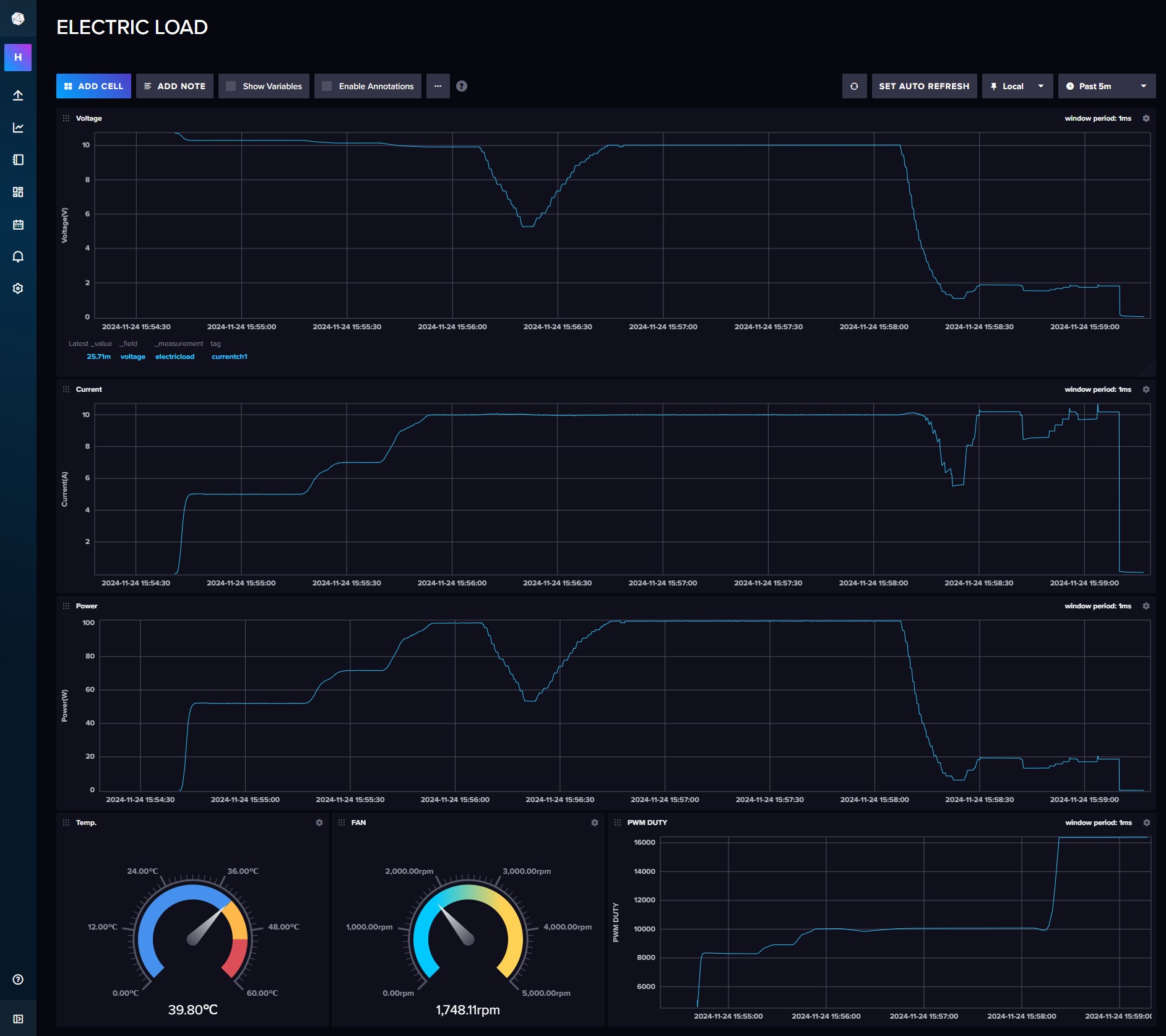
You can see the realtime data using Dashboard by InfluxDB.
After the measure, to stop logging, press the Center Position of the touch pad during over a second. The load is stopped and the data is not sent to the server.
The dashboard shows the graphs of voltage, current, power consumption, and PWM duty. The temperature of the heat sink and FAN RPM also shown in the dashboard.
Using Ubuntu 22.04.3 LTS and ESP-IDF V5.2.1
Ensure that your system meets the following requirements before proceeding with the installation:
Update your system and install the necessary packages using:
sudo apt update && sudo apt -y install git python3 python3-pip gcc build-essential curl pkg-config libudev-dev libtinfo5 clang libclang-dev llvm-dev udev libssl-dev python3.10-venvInstall Rust programming language and Cargo package manager:
curl --proto '=https' --tlsv1.2 -sSf https://sh.rustup.rs | shAfter installation, activate Rust by sourcing the environment:
. "$HOME/.cargo/env"Install the following Rust tools:
Use the following commands:
cargo install ldproxy
cargo install espup
cargo install cargo-espflash
2024-08-12, cargo-espflash can not be compiled. If you have an error, use the following command.
cargo install cargo-binstall
cargo binstall cargo-espflash Run the following command to install and update the Espressif Rust ecosystem:
espup install
espup update
Set up environment variables:
. ./export-esp.shConfigure udev rules for device permissions:
sudo sh -c 'echo "SUBSYSTEMS==\"usb\", ATTRS{idVendor}==\"303a\", ATTRS{idProduct}==\"1001\", MODE=\"0666\"" > /etc/udev/rules.d/99-esp32.rules'
sudo udevadm control --reload-rules
sudo udevadm triggerClone the TimeLeapCam repository:
git clone https://github.com/hnz1102/electricload.git
cd electricload/codeChange the following configuration file: cfg.toml
You have to set the following parameters. WiFi SSID, Password, InfluxDB Server IP Address, InfluxDB API Key, and InfluxDB API with your ORG.
You can get the API Key from the InfluxDB Web Console. Please see the 'How to Install the influxDB and Configure the Dashboard' section No.3.
[electricload]
wifi_ssid = "<Your AP SSID>"  # Set your AP SSID
wifi_psk = "<Your AP Password>" # Set your AP Password
http_server = "<InfluxDB Server IP Address:Port>" # Set your InfluxDB Server IP Address and Port ex. 192.168.1.100:8086
pid_kp = "0.001"
pid_ki = "0.022"
pid_kd = "0.00001"
pwm_offset = "4500"
max_current_limit = "15.0"
max_power_limit = "105.0"
influxdb_api_key = "<InfluxDB API KEY>" # Set your InfluxDB API Key
influxdb_api = "/api/v2/write?org=<ORG>&bucket=LOGGER&precision=ns" # Set your InfluxDB API with your ORG and BUCKET ex. /api/v2/write?org=ORG&bucket=LOGGER&precision=ns
influxdb_tag = "currentch1"
influxdb_measurement = "electricload"Build the project.
cargo build --releaseConnect the Electric Load and Logger to your PC using a USB cable. Then, flash the firmware:
cargo espflash flash --release --monitorIf your device is not detected, power on the device and during the boot, press the BOOT button.
Then, run the flash command again.
After flashing the firmware, the console shows the booting messages.
[2024-11-24T08:43:44Z INFO ] 🚀 A new version of cargo-espflash is available: v3.2.0
[2024-11-24T08:43:44Z INFO ] Serial port: '/dev/ttyACM0'
[2024-11-24T08:43:44Z INFO ] Connecting...
[2024-11-24T08:43:44Z INFO ] Using flash stub
Finished `release` profile [optimized] target(s) in 0.19s
Chip type:         esp32s3 (revision v0.1)
Crystal frequency: 40 MHz
Flash size:        16MB
Features:          WiFi, BLE
MAC address:       xx:xx:xx:xx:xx:xx
Bootloader:        /esp32/electricload/code/target/xtensa-esp32s3-espidf/release/build/esp-idf-sys-37f4c3bc37bda4bb/out/build/bootloader/bootloader.bin
Partition table:   partitions.csv
App/part. size:    1,358,304/15,728,640 bytes, 8.64%
[2024-11-24T08:43:45Z INFO ] Segment at address '0x0' has not changed, skipping write
[2024-11-24T08:43:45Z INFO ] Segment at address '0x8000' has not changed, skipping write
[2024-11-24T08:43:46Z INFO ] Segment at address '0x10000' has not changed, skipping write
[2024-11-24T08:43:46Z INFO ] Flashing has completed!
Commands:
    CTRL+R    Reset chip
    CTRL+C    Exit

ESP-ROM:esp32s3-20210327
Build:Mar 27 2021
rst:0x15 (USB_UART_CHIP_RESET),boot:0x8 (SPI_FAST_FLASH_BOOT)$ wget https://dl.influxdata.com/influxdb/releases/influxdb2-2.7.0-amd64.deb
$ sudo dpkg -i influxdb2-2.7.0-amd64.deb
$ sudo service influxdb startConnect to the 'http://<influxDB installed PC Address>:8086'Click GET STARTED and set Username, Password, Initial Organization Name, and Initial Bucket Name
| Term | Value |
|---|---|
| Username | Set login username as influxDB administrator web console |
| Password | Set login password as influxDB administrator web console |
| Initial Organization Name | Organization Name ex. ORG |
| Initial Bucket Name | LOGGER |
After set them, click CONTINUE.
You can see the operator API token on the browser. YOU WON'T BE ABLE TO SEE IT AGAIN!
If you want to get new API token, click API Tokens menu form Sources Icon, then click GENERATE API TOKEN and select All access token, click Save.
You can see a new API token and get it.
After copy the token, click CONFIGURE LATER.
Click the Dashboard icon, and select Import Dashboard from the CREATE DASHBOARD menu.
Drop the influxdb/electric_load.json file to Drop a file here, then click IMPORT JSON AS DASHBOARD.
You can see the ELECTRIC LOAD pannel on the Dashboards page.
Click this panel, and You can see the dashboard.
If you want to customize the dashboard design, click configure mark. You can change the graph design.
There is a Schematic data in hardware directory. If you want to make the PCB, you can order the PCBway this link. The heat sink is not included in the schematic data. You can use the heat sink with the fan for LGA115x CPU Cooler.
I used this heat sink
I guess another heat sink is also good.
This PCB is designed by Kicad. This board image photo is shown the jumper wire. But, the PCB data is already fixed the error.
UPDATE 2024-12-29: I changed the OpAmp from TSB6111ILT to OPA187IDBVR. OPA187IDBVR is a low noise and low offset voltage OpAmp. It can be used for the high precision control.
under_voltage_limit configuration parameter. When the voltage drops below this threshold, the PID controller is reset to prevent inrush current during startup or low voltage conditions.max_current_limit_ratio parameter. When the actual current exceeds the set current multiplied by this ratio, the PID controller is reset and output is set to zero to protect against excessive current flow.Note: After updating to v0.1.2, it is necessary to reconfigure the cfg.toml file to include the new parameters. Some PID parameters are changed, so please update them accordingly.
This source code is licensed under MIT. Other Hardware Schematic documents are licensed under CC-BY-SA V4.0.
| Qty | Value | Footprint | References |
|---|---|---|---|
| 12 | 10K | Resistor_SMD:R_0603_1608Metric | R201, R205, R206, R301, R302, R305, R402, R403, R404, R502, R503, R505 |
| 11 | 0.1uF | Capacitor_SMD:C_0603_1608Metric | C201, C202, C205, C301, C302, C404, C405, C408, C410, C501, C502 |
| 5 | 10uF | Capacitor_SMD:C_0805_2012Metric | C203, C206, C208, C401, C403 |
| 5 | GND | TestPoint:TestPoint_Pad_D1.0mm | TP405, TP406, TP407, TP408, TP409 |
| 3 | 10K 1% | Resistor_SMD:R_0603_1608Metric | R204, R401, R410 |
| 3 | 1K 1% | Resistor_SMD:R_0603_1608Metric | R405, R411, R412 |
| 3 | 1uF | Capacitor_SMD:C_0805_2012Metric | C204, C402, C406 |
| 2 | 100 | Resistor_SMD:R_0603_1608Metric | R407, R504 |
| 2 | 10m | Library:R_10mOHM | R408, R409 |
| 2 | 150R | Resistor_SMD:R_0603_1608Metric | R303, R304 |
| 2 | Screw_Terminal_3P | Library:TB112-2-2-3-E-1 Terminal Block | J401, J402 |
| 2 | TSB611ILT | Package_TO_SOT_SMD:SOT-23-5 | U401, U404 |
| 1 | +12V | TestPoint:TestPoint_Pad_D1.0mm | TP203 |
| 1 | +3.3V | TestPoint:TestPoint_Pad_D1.0mm | TP201 |
| 1 | 1000pF | Capacitor_SMD:C_0603_1608Metric | C409 |
| 1 | 1K | Resistor_SMD:R_0603_1608Metric | R202 |
| 1 | 1k | Resistor_SMD:R_0603_1608Metric | R501 |
| 1 | 2.2uF | Capacitor_SMD:C_0805_2012Metric | C207 |
| 1 | 2K 1% | Resistor_SMD:R_0603_1608Metric | R406 |
| 1 | 2N7002K | Package_TO_SOT_SMD:SOT-23 | Q501 |
| 1 | 3.5x2.6 Tact SW | Library:WS-TASV SMT Tact Switch | SW301 |
| 1 | 4.7uF | Capacitor_SMD:C_0805_2012Metric | C407 |
| 1 | 4PIN FANCTL | Connector:FanPinHeader_1x04_P2.54mm_Vertical | J501 |
| 1 | 75K 1% | Resistor_SMD:R_0603_1608Metric | R203 |
| 1 | BOOT | TestPoint:TestPoint_Pad_D1.0mm | TP302 |
| 1 | CH224K | Library:ESSOP-10_3.9x4.9mm_P1.00mm | U202 |
| 1 | ESP32-S3-WROOM-1-N16R8 | Library:ESP32-S3-WROOM-1_EXP | U301 |
| 1 | FingerTouchPad | Library:FingerTouchPad_34x35mm | J301 |
| 1 | GND | Library:TestPoint_Pad_3.2x1.6mm | TP-PAD401 |
| 1 | INA228 | Package_SO:VSSOP-10_3x3mm_P0.5mm | U402 |
| 1 | IRF530 | Package_TO_SOT_THT:TO-220-3_Horizontal_TabUp | Q401 |
| 1 | IRF7606PBF | Package_SO:MSOP-8_3x3mm_P0.65mm | Q201 |
| 1 | LD1117S33TR | Package_TO_SOT_SMD:SOT-223-3_TabPin2 | U201 |
| 1 | LM35-NEB | Package_TO_SOT_THT:TO-220-3_Horizontal_TabDown | U403 |
| 1 | MBR3060FCT | Package_TO_SOT_THT:TO-220-3_Horizontal_TabUp | D401 |
| 1 | MH2029-601Y | Inductor_SMD:L_0805_2012Metric | FB201 |
| 1 | OP-VCC | TestPoint:TestPoint_Pad_D1.0mm | TP404 |
| 1 | PWM | TestPoint:TestPoint_Pad_D1.0mm | TP401 |
| 1 | RESET | TestPoint:TestPoint_Pad_D1.0mm | TP301 |
| 1 | SET-Vr | TestPoint:TestPoint_Pad_D1.0mm | TP402 |
| 1 | SPX3819M5-L | Package_TO_SOT_SMD:SOT-23-5 | U203 |
| 1 | SSD1331_DISPLAY | Library:OLED SSD1331 SPI DISPLAY | U302 |
| 1 | SSM3J332R | Package_TO_SOT_SMD:SOT-23 | Q502 |
| 1 | SolderJumper_2_Open | Jumper:SolderJumper-2_P1.3mm_Bridged_RoundedPad1.0x1.5mm | JP401 |
| 1 | USB4105-GF-A | Library:USB_C_5077CR-16-SMC2-BK-TR | J201 |
| 1 | VBUS | TestPoint:TestPoint_Pad_D1.0mm | TP202 |
| 1 | Vfb | TestPoint:TestPoint_Pad_D1.0mm | TP403 |
| 1 | Vgs | TestPoint:TestPoint_Pad_D1.0mm | TP410 |
The 88 most common of 96 parts.
It measures 185 × 98 mm and has 2 copper layers, 1.6 mm thick.
96 parts, built around the ESP32-S3-WROOM-1-N16R8, TSB611ILT, CH224K and LD1117S33TR(MS). The full list of its parts is on this page, with links to each part's symbol and footprint where PCBKit's library has them.
From the hnz1102/electricload repository on GitHub, at the commit this page was made from: the board is hardware/mosfetload.kicad_pcb and its schematic hardware/esp32_cont.kicad_sch. PCBKit opens the board in the browser, with nothing to install.
Its repository states no licence, so its author keeps all rights: ask hnz1102 before reusing the design.
hnz1102/dcpower
DC Power Unit for Breadboard based on ESP32-S3 microcontroller and AP33772S USB Power Delivery (PD) Sink Controller.


hnz1102/EEW-display
ESP32-S3 firmware for a small earthquake-information display. It shows recent earthquakes and emergency earthquake warnings (緊急地震速報, EEW) from [P2P地震情報](https://www.p2pquake.net/), draws the epicenters on a Google map…

hnz1102/mini-current-meter
Mini Current Meter using INA228A ultra-precise digital power monitor


hnz1102/ssh-serial-bridge
Firmware for the ESP32-S3 that bridges an SSH connection (over Wi-Fi) to UART and USB CDC serial ports. Written in Rust (esp-idf-hal / esp-idf-svc) with a C component (wolfSSH) for the SSH server.

hnz1102/mini-power
Mini-Power is a small, portable DC power supply unit designed to provide a convenient and reliable source of adjustable voltage for your electronic devices and breadboard experiments.

hnz1102/sdcdmux-emmc
SD CARD and eMMC Device Multiplexer with Infrared Remote Controller