2 layers122.2 × 122.8 mm
Dcpower
hnz1102/dcpower
DC Power Unit for Breadboard based on ESP32-S3 microcontroller and AP33772S USB Power Delivery (PD) Sink Controller.
115 parts1

 hnz1102/mini-power3
Mini-Power is a small, portable DC power supply unit designed to provide a convenient and reliable source of adjustable voltage for your electronic devices and breadboard experiments.
Mini power is an open-source printed circuit board by hnz1102, from the hnz1102/mini-power repository on GitHub. It is a 2-layer board of 46 × 54 mm with 52 parts on 50 nets, routed with 453 tracks and 131 vias.
It is built around the ESP32-C3-WROOM-02-N4, AP33772SDKZ-13-FA01 and PCA9306D, with the 0.1UF 50V 5*11, DMN3008SFG and MH2029-601Y among its other parts. Its parts include 19 resistors, 12 capacitors, 5 ICs, 3 connectors and 3 switches. It belongs with the power boards and the ESP32 and RISC-V boards of this library.


Mini Power for Breadboard
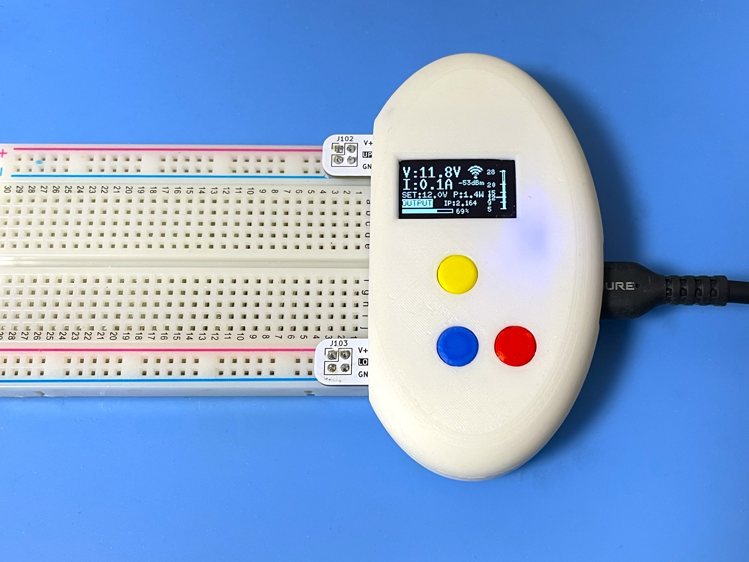
Mini-Power is a small, portable DC power supply unit designed to provide a convenient and reliable source of adjustable voltage for your electronic devices and breadboard experiments. Powered from a USB Power Delivery (PD) charger, it supports both Standard Power Range (SPR) and Extended Power Range (EPR) modes, making it perfect for electronics developers, students, and anyone who needs a compact bench power supply.
| Reference | Part | Description |
|---|---|---|
| U103 | ESP32-C3-WROOM-02-N4 | Main microcontroller (RISC-V, built-in WiFi, 4MB flash) |
| U104 | AP33772SDKZ-13-FA01 | USB Power Delivery Sink Controller (SPR + EPR), QFN4040-24 |
| U102 | SSD1306 | Monochrome OLED display (128×64 pixels, I2C) |
| U101 | PCA9306D | Dual bidirectional I2C voltage-level translator (SSOP-8) |
| U105 | NJW1933F1 | Synchronous step-down DC/DC converter for 3.3V supply (SOT-23-6) |
| Q101, Q102 | DMN3008SFG | Dual N-channel MOSFET for output switching (PowerDI3333-8) |
| J101 | USB4105-GF-A | USB Type-C connector (input) |
| J102, J103 | 2×2 pin header | Output terminals (UPPER OUT / LOWER OUT), 2.54mm pitch |
| SW101–SW103 | TS-06104 | Push buttons: Up (GPIO10), Down (GPIO20), Center (GPIO21) |
| R110 | 5mΩ shunt resistor | Current sensing resistor (2512 package) |
| L101 | 22µH | Inductor for DC/DC converter |
| D101 | LED (Blue) | Status indicator |
| D102 | SK36A-LTP | Schottky diode (SMA) |
| FB101 | MH2029-601Y | Ferrite bead for EMI filtering |
Schematic and PCB files are in the hardware/ directory. The board is designed with KiCad. A PDF export of the schematic is available at hardware/schematic.pdf.
The ap33772s-driver crate is used for all USB-PD communication with the AP33772S controller.
The firmware is written entirely in Rust using the ESP-IDF framework.
| File | Responsibility |
|---|---|
main.rs | Startup, peripheral init, NVS load/save, main control loop |
usbpd.rs | AP33772S PD driver wrapper (PDO negotiation, custom voltage request, VOUT control) |
displayctl.rs | SSD1306 OLED driver, display thread, PDO list screen |
currentlogs.rs | In-memory ring buffer (up to 127 records) for voltage/current/power/temp data |
transfer.rs | InfluxDB Line Protocol HTTP transfer thread |
httpserver.rs | HTTP server, REST API (/api/status, /api/voltage, /api/output, /api/pdos), embedded HTML/JS |
keyevent.rs | GPIO key scanner (10ms polling, 100ms guard time) with long-press detection |
wifi.rs | WiFi connection, RSSI monitoring, automatic reconnect |
syslogger.rs | RFC 5424 UDP syslog, replaces the default ESP console logger |
http://<device-ip>/ in a browser.Note *1: When it doesn't connect to the PD charger, the display will show "No PD Power". Click the up/down buttons to show main screen. It only can output 5V. *2: If it can't connect to WiFi, the display will show the main screen after 30 seconds, but without IP address and RSSI.
| Button | GPIO | Function |
|---|---|---|
| Up | GPIO10 | Increase output voltage by 0.1V |
| Down | GPIO20 | Decrease output voltage by 0.1V |
| Center | GPIO21 | Toggle output ON/OFF |
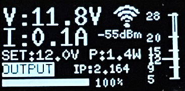
The SSD1306 128×64 monochrome OLED display is divided into several regions as shown below.
| Area | Content | Detail |
|---|---|---|
V:xx.xV | Measured voltage | Read from AP33772S (updated every 100ms when output ON) |
I:xx.xA | Measured current | Read from AP33772S (updated every 100ms when output ON) |
SET:xx.xV | Target output voltage | Blinks while PD voltage negotiation is in progress |
P:xx.xW / P:xx.xmW | Measured power | Auto-range: switches between mW and W (threshold 0.5W / 1.0W) |
OUTPUT / STOPPED | Output state | OUTPUT shown inverted (white on black) when output is ON |
| IP address | Last two octets of device IP | e.g. IP:2.142 for 192.168.2.142 |
| Buffer bar | InfluxDB send buffer usage | 60px wide bar; fills left-to-right as records accumulate (max 127) |
xxx% | Buffer usage percentage | Displayed to the right of the buffer bar |
| WiFi icon | WiFi signal strength | 5-level icon (wifi-0 to wifi-4) based on RSSI; animated while connecting |
+xx dBm | RSSI value | Shown below WiFi icon when connected |
| Voltage bar (right edge) | PDO voltage range | Vertical bar showing min–max PD voltage; Variable/PPS range filled, Fixed PDO voltages marked as horizontal lines; current SET voltage shown as a longer line marker |
Startup sequence:
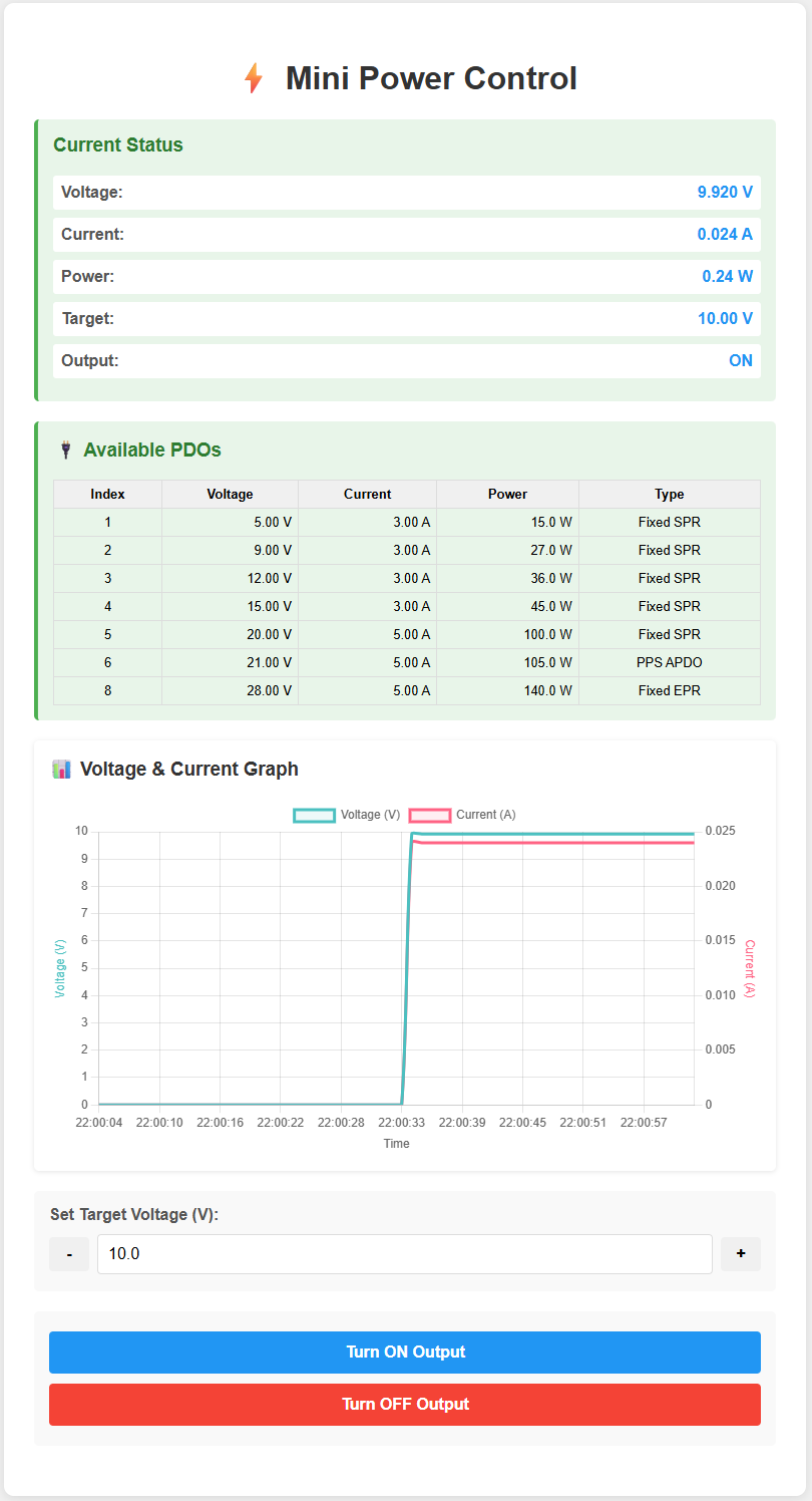
Voltage Overshoot, Current OV x.xxxA) replace the main screen temporarily and auto-dismiss after 3 seconds.When connected to WiFi, open http://<device-ip>/ (IP shown on OLED display) to access:
| Protection | Mechanism |
|---|---|
| Over Voltage Protection (OVP) | AP33772S hardware |
| Under Voltage Protection (UVP) | AP33772S hardware |
| Over Current Protection (OCP) | AP33772S hardware |
| Software current limit | Output disabled if current exceeds max_current_limit |
| Software power limit | Output disabled if power exceeds max_power_limit |
| Voltage overshoot detection | Output disabled if measured voltage > 110% of setpoint |
1. Install Rust Compiler
sudo apt update && sudo apt -y install git python3 python3-pip gcc build-essential \
curl pkg-config libudev-dev libtinfo5 clang libclang-dev llvm-dev udev libssl-dev python3.10-venv nanocurl --proto '=https' --tlsv1.2 -sSf https://sh.rustup.rs | sh
# Select option 1 (default install)source "$HOME/.cargo/env"2. Install toolchain for ESP32-C3
cargo install ldproxy
cargo install cargo-binstall
cargo install espup
espup install
espup update
. ./export-esp.sh
cargo binstall cargo-espflash
3. Add UDEV rules
sudo sh -c 'echo "SUBSYSTEMS==\"usb\", ATTRS{idVendor}==\"303a\", ATTRS{idProduct}==\"1001\", MODE=\"0666\"" \
  > /etc/udev/rules.d/99-esp32.rules'
sudo udevadm control --reload-rules
sudo udevadm trigger
4. Clone the repository
git clone https://github.com/hnz1102/mini-power.git
cd mini-power/code
5. Configure WiFi and InfluxDB
cp cfg.toml.samp cfg.toml
nano cfg.toml[mini-power]
wifi_ssid = "YOUR_WIFI_SSID"
wifi_psk = "YOUR_WIFI_PASSWORD"
influxdb_server = "192.168.x.x:8086"
influxdb_api_key = "<YOUR_API_KEY>"
influxdb_api = "/api/v2/write?org=<ORG>&bucket=LOGGER&precision=ns"
influxdb_measurement = "minipower"
influxdb_tag = "ch"
max_current_limit = "5.2"
max_power_limit = "100.0"
max_temperature = "75"
syslog_server = "192.168.x.x:514"
syslog_enable = "false"6. Connect the board and verify
cargo espflash board-info
# Select /dev/ttyACM0
# Expected: Chip type: esp32c3, Flash size: 4MB
7. Build and flash
cargo espflash flash --release --monitorThe device boots automatically after flashing. The OLED display will show the PDO list negotiated with the charger, then switch to the main monitoring screen.
1. Download and install InfluxDB
wget https://dl.influxdata.com/influxdb/releases/influxdb2-2.7.0-amd64.deb
sudo dpkg -i influxdb2-2.7.0-amd64.deb
sudo service influxdb start
2. Initial configuration
Open http://<server-ip>:8086. Click GET STARTED and set:
| Term | Value |
|---|---|
| Username | Admin login username |
| Password | Admin login password |
| Initial Organization Name | e.g. ORG |
| Initial Bucket Name | LOGGER |
3. Get the API Token
Copy the Operator API Token shown after setup — you will not see it again. To generate a new token later: API Tokens → GENERATE API TOKEN → All access token.
4. Import the Dashboard Template
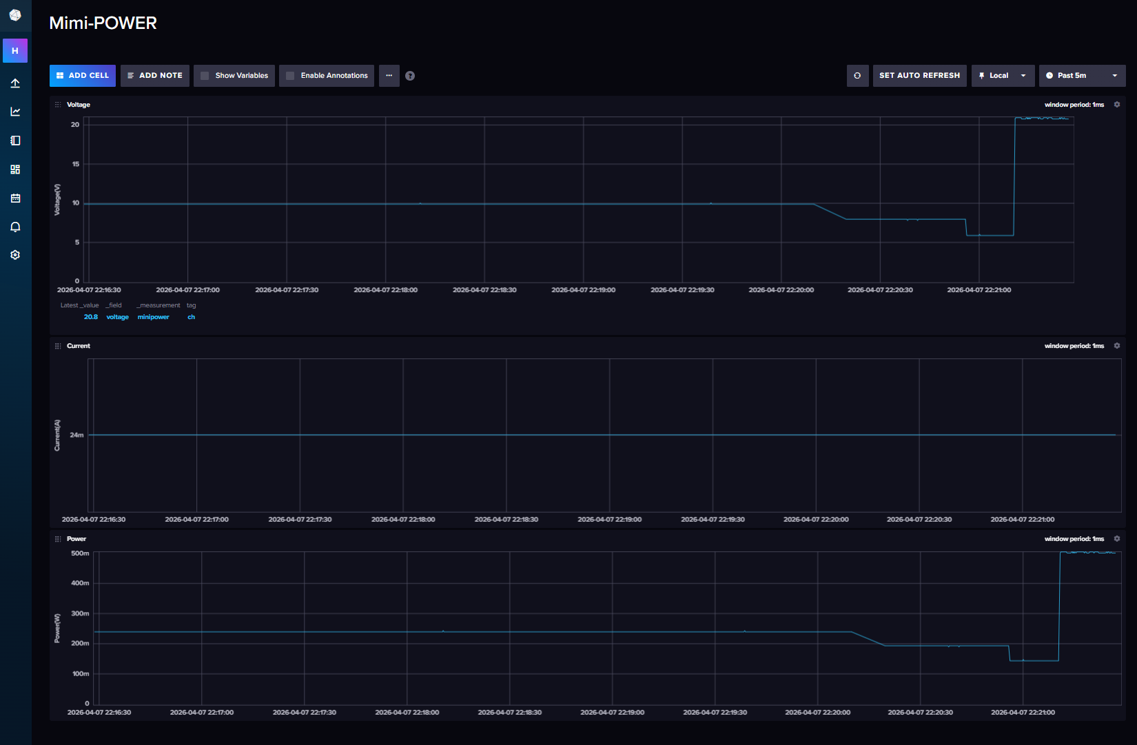
Click Dashboard → CREATE DASHBOARD → Import Dashboard. Drop the influxdb/mimi-power.json file into the import dialog, then click IMPORT JSON AS DASHBOARD.
You will see the Mimi-POWER dashboard. It contains three time-series graphs:
| Chart | Field | Unit |
|---|---|---|
| Voltage | voltage | V |
| Current | current | A |
| Power | power | W |
All charts query the LOGGER bucket, measurement minipower, tag tag = "ch".
5. Start logging
Enable the output on the Mini-Power unit (Center button or web interface). Measurement data will be sent to InfluxDB and appear on the dashboard in real-time.
The PCB is designed with KiCad. All hardware design files are in the hardware/ directory.
| File / Directory | Description |
|---|---|
hardware/schematic.pdf | Schematic PDF (for viewing without KiCad) |
hardware/mini-power.kicad_sch | KiCad schematic source |
hardware/mini-power.kicad_pcb | KiCad PCB layout |
hardware/bom.csv | Bill of Materials |
hardware/production/ | Gerber files for PCB manufacturing (mini-power.kicad_pcb_gerber.zip) |
The enclosure design files are in the hardware/Container/ directory.
| File | Description |
|---|---|
body.3mf | Main enclosure body |
upper.3mf | Top cover |
button.3mf | Button cap for the three push switches |
mini-power.f3d | Fusion 360 source file |
All parts are designed for FDM 3D printing. Print body.3mf, upper.3mf, and three copies of button.3mf.
This source code is licensed under MIT. Other Hardware Schematic documents are licensed under CC-BY-SA V4.0.
| Qty | Value | Footprint | References |
|---|---|---|---|
| 8 | 10K | Resistor_SMD:R_0603_1608Metric | R101, R105, R107, R111, R117, R118, R119, R120 |
| 5 | 0.1uF/50V | Capacitor_SMD:C_0603_1608Metric | C102, C103, C105, C106, C108 |
| 3 | 10uF/50V | Capacitor_SMD:C_0805_2012Metric | C104, C107, C111 |
| 3 | 5K1 | Resistor_SMD:R_0603_1608Metric | R103, R104, R116 |
| 3 | TS-06104 | Library:TS-06104 | SW101, SW102, SW103 |
| 2 | 1uF | Capacitor_SMD:C_0805_2012Metric | C101, C110 |
| 2 | 4.7K | Resistor_SMD:R_0603_1608Metric | R108, R109 |
| 2 | DMN3008SFG | Package_SON:Diodes_PowerDI3333-8 | Q101, Q102 |
| 1 | 100 | Resistor_SMD:R_0603_1608Metric | R114 |
| 1 | 10R | Resistor_SMD:R_0603_1608Metric | R112 |
| 1 | 1K | Resistor_SMD:R_0603_1608Metric | R106 |
| 1 | 2.2uF/50V | Capacitor_SMD:C_0603_1608Metric | C109 |
| 1 | 200K | Resistor_SMD:R_0603_1608Metric | R102 |
| 1 | 22uH | Library:L_CHPH4D19FNP | L101 |
| 1 | 3K09 | Resistor_SMD:R_0603_1608Metric | R115 |
| 1 | 3V3 | TestPoint:TestPoint_Pad_D1.0mm | TP103 |
| 1 | 47uF | Capacitor_SMD:C_0805_2012Metric | C112 |
| 1 | 5V | TestPoint:TestPoint_Pad_D1.0mm | TP101 |
| 1 | 5m | Resistor_SMD:R_2512_6332Metric_Pad1.40x3.35mm_HandSolder | R110 |
| 1 | AP33772SDKZ-13-FA01 | Library:W-QFN4040-24_Type_A1_DIO | U104 |
| 1 | ESP32-C3-WROOM-02-N4 | Library:IC18_ESP32-C3-WROOM-02-N4_EXP | U103 |
| 1 | LED BLUE | LED_SMD:LED_0603_1608Metric | D101 |
| 1 | LOWER OUT | Connector_PinHeader_2.54mm:PinHeader_2x02_P2.54mm_Vertical | J103 |
| 1 | MH2029-601Y | Inductor_SMD:L_0805_2012Metric | FB101 |
| 1 | NJW1933F1 | Package_TO_SOT_SMD:SOT-23-6 | U105 |
| 1 | PCA9306D | Package_SO:SSOP-8_2.95x2.8mm_P0.65mm | U101 |
| 1 | SK36A-LTP | Diode_SMD:D_SMA | D102 |
| 1 | SSD1306_DISPLAY | Library:OLED I2C DISPLAY | U102 |
| 1 | SolderJumper_2_Open | Jumper:SolderJumper-2_P1.3mm_Open_RoundedPad1.0x1.5mm | JP101 |
| 1 | UPPER OUT | Connector_PinHeader_2.54mm:PinHeader_2x02_P2.54mm_Vertical | J102 |
| 1 | USB4105-GF-A | Library:USB_C_5077CR-16-SMC2-BK-TR | J101 |
| 1 | VDD | TestPoint:TestPoint_Pad_D1.0mm | TP102 |
hnz1102/dcpower
DC Power Unit for Breadboard based on ESP32-S3 microcontroller and AP33772S USB Power Delivery (PD) Sink Controller.

kristofkatzenberger/windsensor
This repository contains the design files for a portable wind sensor developed in 2025/26 at the University of Applied Sciences Technikum Wien. This project was completed as part of the Bachelor's Thesis:

hnz1102/mini-current-meter
Mini Current Meter using INA228A ultra-precise digital power monitor


motor-and-motion-control-lab/mmlab-12PhaseDrive-388Slave
PCB Electronics for Humanoid Robots and Bearingless Motor Systems


hnz1102/ssh-serial-bridge
Firmware for the ESP32-S3 that bridges an SSH connection (over Wi-Fi) to UART and USB CDC serial ports. Written in Rust (esp-idf-hal / esp-idf-svc) with a C component (wolfSSH) for the SSH server.

hnz1102/EEW-display
ESP32-S3 firmware for a small earthquake-information display. It shows recent earthquakes and emergency earthquake warnings (緊急地震速報, EEW) from [P2P地震情報](https://www.p2pquake.net/), draws the epicenters on a Google map…
It measures 46 × 54 mm and has 2 copper layers, 1.6 mm thick.
52 parts, built around the ESP32-C3-WROOM-02-N4, AP33772SDKZ-13-FA01, PCA9306D and 0.1UF 50V 5*11. The full list of its parts is on this page, with links to each part's symbol and footprint where PCBKit's library has them.
From the hnz1102/mini-power repository on GitHub, at the commit this page was made from: the board is hardware/mini-power.kicad_pcb and its schematic hardware/mini-power.kicad_sch. PCBKit opens the board in the browser, with nothing to install.
Its repository states no licence, so its author keeps all rights: ask hnz1102 before reusing the design.