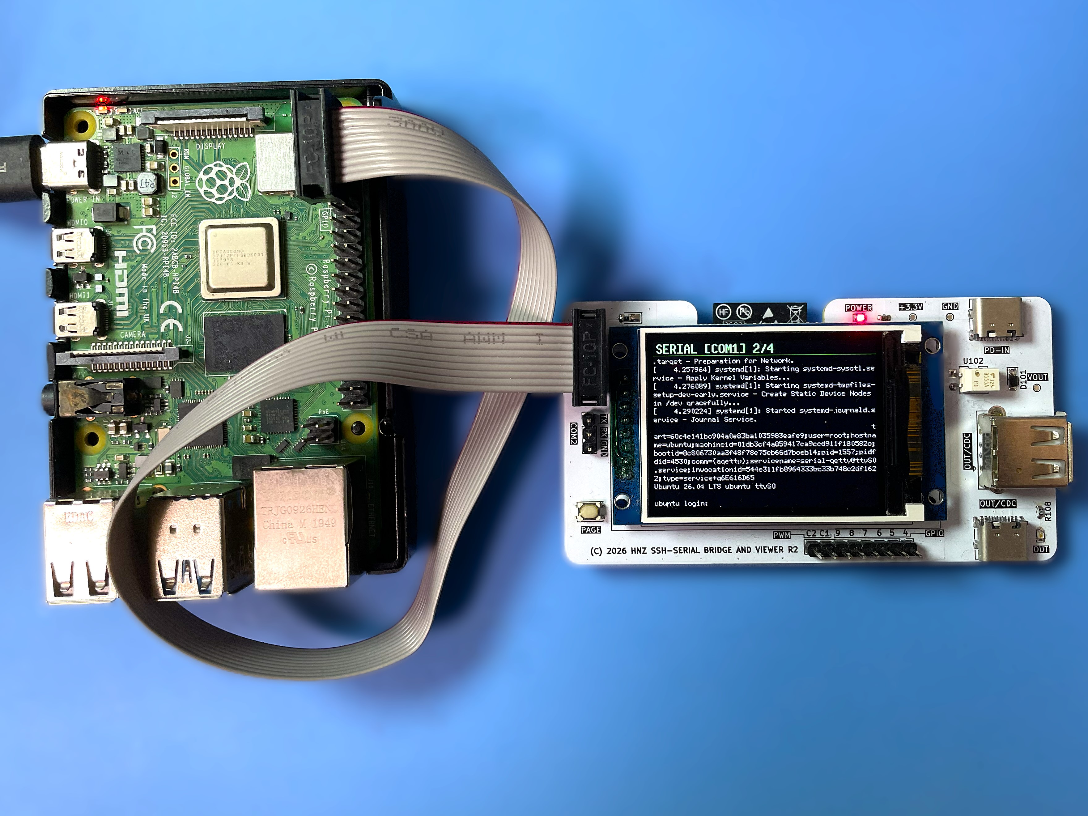
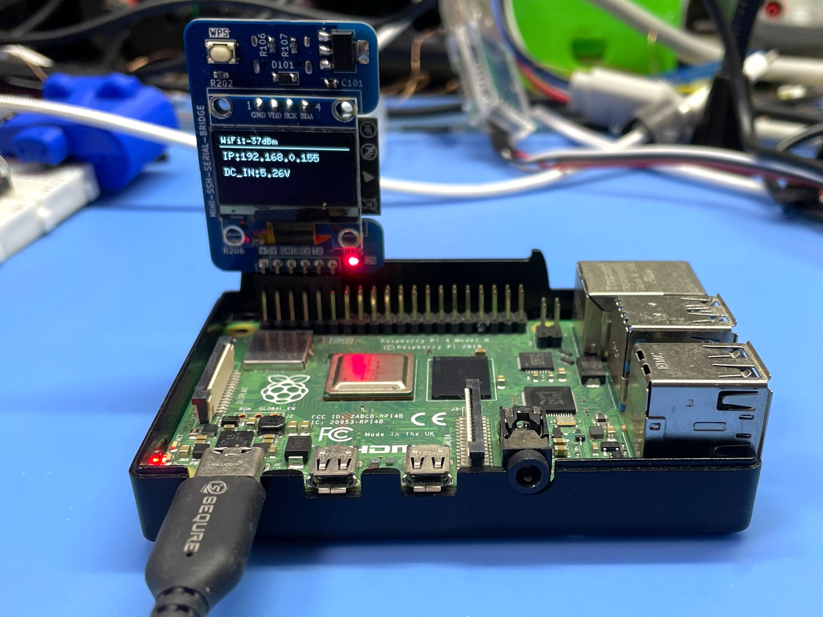
Firmware for the ESP32-S3 that bridges an SSH connection (over Wi-Fi) to UART and USB CDC serial ports. Written in Rust (esp-idf-hal / esp-idf-svc) with a C component (wolfSSH) for the SSH server.
Ssh bridge for raspberrypi is an open-source printed circuit board by hnz1102, from the hnz1102/ssh-serial-bridge repository on GitHub. It is a 2-layer board of 93 × 50 mm with 37 parts on 59 nets, routed with 307 tracks and 107 vias.
It is built around the ESP32-S3-WROOM-1-N16R8, AZ1117CH-3.3TRG1-50 and TLP3555A(F, with the USB4105-GF-A, CUHS20F60,H3F and MH2029-601Y among its other parts. Its parts include 15 resistors, 6 connectors, 4 capacitors, 4 ICs and 3 diodes. It belongs with the interfaces and adapters and radio and wireless boards and the ESP32 boards of this library.
ssh-serial-bridge - SSH-to-Serial Bridge for Raspberry Pi, USB CDC and UART
Firmware for the ESP32-S3 that bridges an SSH connection (over Wi-Fi) to UART
and USB CDC serial ports. Written in Rust (esp-idf-hal / esp-idf-svc) with a
C component (wolfSSH) for the SSH server.
Features
Feature
Description
SSH server
Port 22, username/password authentication via wolfSSH, multiple concurrent sessions (including shared sessions on the same serial port)
Serial ports
COM1 / COM2 (UART) and USB CDC (USB Host) — up to 4 ports (usb0–usb3)
Web UI
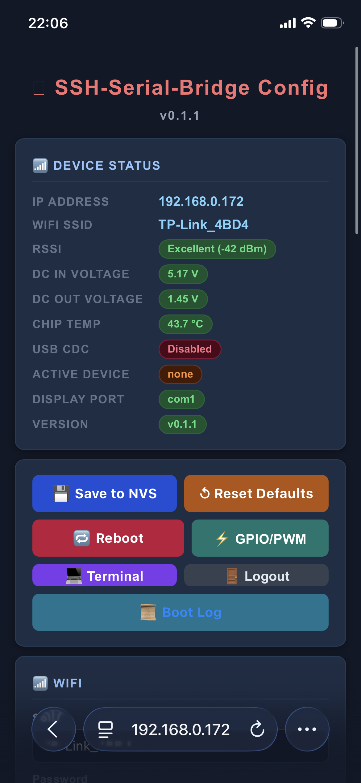
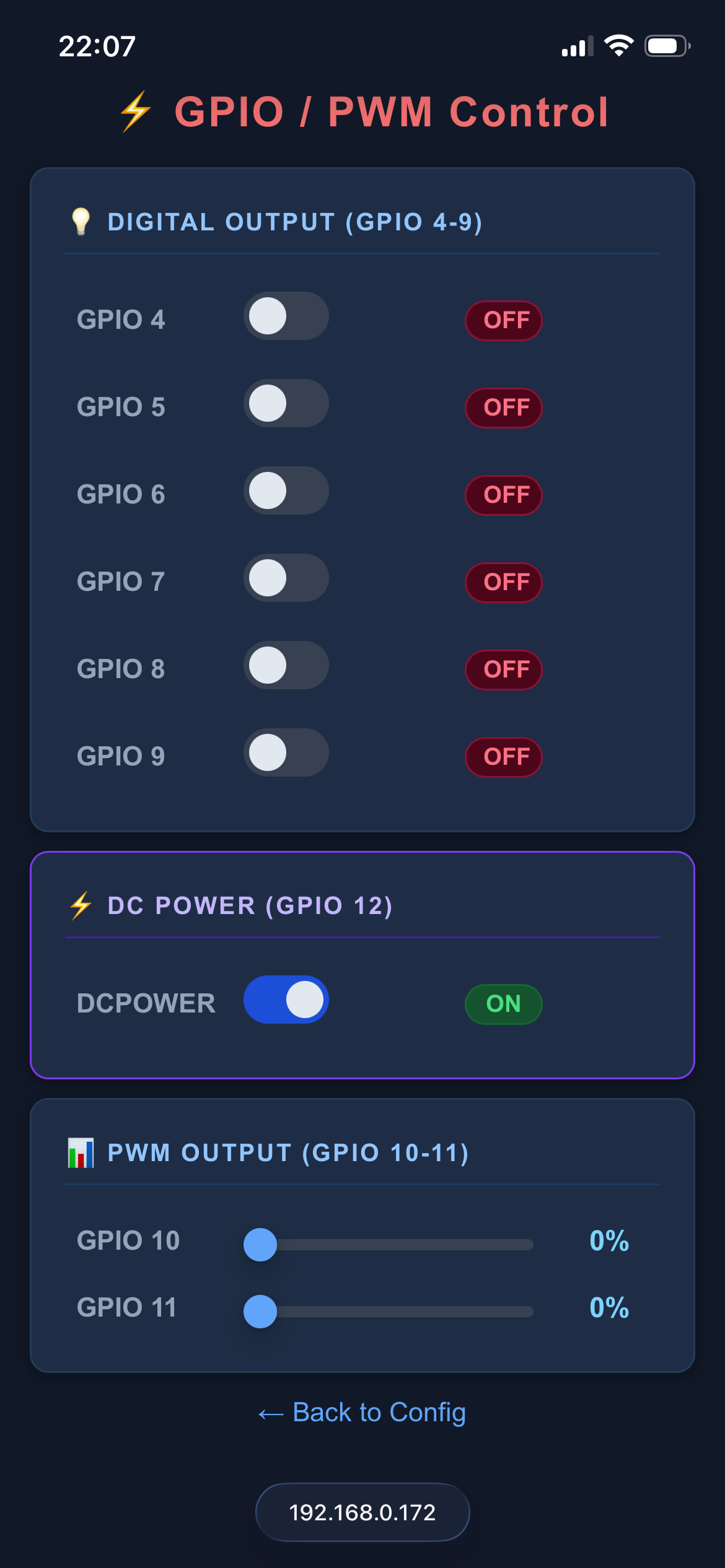
Browser-based configuration, terminal, and GPIO control
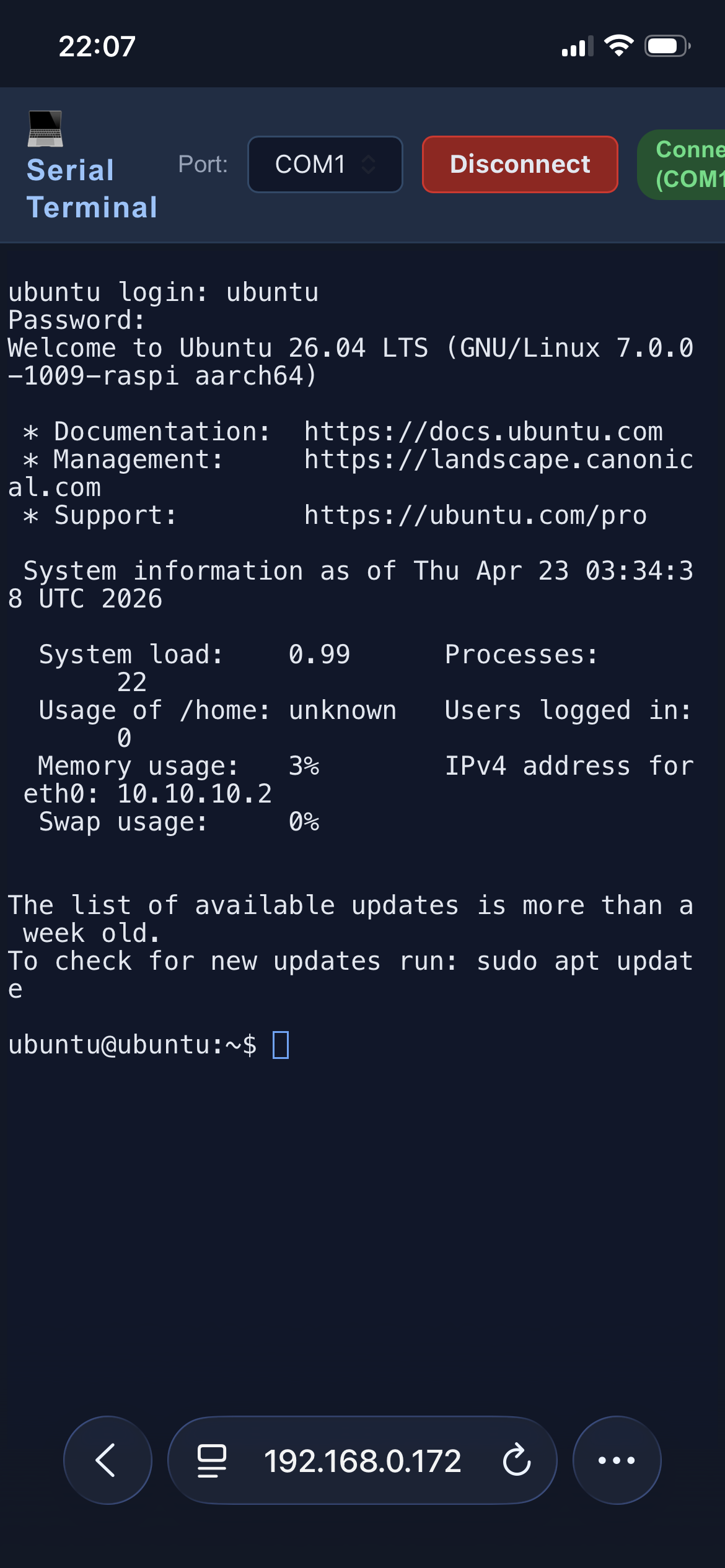
WebSocket terminal
Built-in xterm.js; access serial data from the browser at /terminal
WPS support
Wi-Fi Protected Setup (PBC mode) — configure Wi-Fi via button or Web UI
GPIO / PWM
Digital output (ON/OFF) on GPIO 4–9, 12 ; PWM output on GPIO 10–11
SPI display
Optional ST7789V (320×240) display showing incoming serial data
UDP Syslog
RFC 5424 remote logging over UDP
NTP
Time synchronisation on boot; up to 4 servers configurable via Web UI
NVS settings
Persistent configuration stored in NVS; editable via Web UI at runtime
Release History
v0.1.2
Fixed the OTA update completion message so it is displayed to the SSH client.
Fixed the Web UI terminal freezing while a serial target is booting.
Improved setup script compatibility across Linux distributions and made Xtensa toolchain setup more robust.
Split large USB CDC writes into multiple bulk transfers.
Fixed device reboot failures.
Fixed the custom partition table path used by the build.
Values in cfg.toml are compiled into the firmware as defaults.
After boot they can be overridden via the Web UI or direct NVS writes; NVS values take priority.
Wi-Fi Setup with WPS
WPS (Wi-Fi Protected Setup) allows you to connect to a Wi-Fi network without manually entering the SSID and password. This device supports WPS Push Button Configuration (PBC) mode.
Method 1: Using cfg.toml and Factory Reset (Recommended for initial setup)
If you don't have Wi-Fi credentials yet or want to reconfigure via WPS without Web UI access:
Edit cfg.toml before building (or rebuild the firmware):
toml
wifi_ssid = ""# Set to empty string
wps_enable = "true"# Enable WPS mode on boot
Flash the firmware to the device
On boot, the device will automatically enter WPS mode and wait for you to press the WPS button on your Wi-Fi router (timeout: 2 minutes)
Upon successful WPS connection, the credentials are saved to NVS and the device reboots
Alternative: Trigger WPS via Factory Reset
If the device is already running with Wi-Fi configured but you want to switch to WPS:
Edit cfg.toml to set wps_enable = "true" and wifi_ssid = ""
Rebuild and flash the firmware
Perform a Factory Reset: Press and hold the BOOT button (GPIO 0) for ≥10 seconds
The device will erase NVS, restore cfg.toml defaults, and reboot into WPS mode
Press the WPS button on your Wi-Fi router within 2 minutes
Note: Web UI is not accessible until Wi-Fi is connected, so this method is essential for initial setup or when you lose Wi-Fi access.
Method 2: Using the Web UI (when already connected to Wi-Fi)
Navigate to the configuration page at http://<device_ip>/
Find the WPS section
Click the "Start WPS" button
Press the WPS button on your Wi-Fi router within 2 minutes
The device will automatically receive and save the Wi-Fi credentials and reboot
Run once after cloning, or after a clean wipe of components/:
bash
cd esp32-s3/ssh-serial-bridge
bash setup_components.sh
This clones wolfssh and wolfssl at the verified commits and places the
ESP-IDF-specific CMakeLists.txt and include/user_settings.h on top.
Build
bash
cargo build --release
Flash and monitor
bash
espflash flash --release --monitor
Creating a complete flash binary image
To create a single binary file that includes all partitions (bootloader,
partition table, data partitions, and the currently built app image) for
distribution or web-based flashing:
This creates a complete 8 MB flash image starting from offset 0x0.
Creating board images for both USB flashing and OTA
The helper script builds all board configs and produces both image types:
flash_images/flash_<board>.bin (merged full-flash image, write at 0x0)
flash_images/app_<board>.bin (app-only image for ssh ... update OTA)
bash
bash build-flash-images.sh
Important: When flashing this image, always write it to offset 0x0, not 0x9000. Writing to 0x9000 will result in a boot failure with "invalid header: 0xffffffff" error.
Flash the complete binary
bash
# Using esptool.py
esptool.py --chip esp32s3 --port /dev/ttyUSB0 write_flash 0x0 complete_flash.bin

# Using espflash
espflash write-bin 0x0 complete_flash.bin
Web-based flashing (no command line required)
You can also flash the binary via a web browser using the ESP Web Flasher:
UART1 (pins configured by com1_tx_pin / com1_rx_pin)
com2
UART2 (pins configured by com2_tx_pin / com2_rx_pin)
The -tt flag forces pseudo-TTY allocation, which is required for correct
terminal behaviour.
A welcome banner is printed on connect:
text
Connected to ESP32-S3 SSH-Serial-Bridge v0.1.1 [com1].
Disconnect: Enter then ~.
The same serial target can be shared by multiple SSH clients. When another
session is already connected to that target, the banner also shows:
text
Note: N other session(s) are also connected to this device — input/output is shared.
Shared-session behaviour on the same target:
RX from device is broadcast to all connected SSH sessions on that target.
TX from each SSH session is sent to the same physical serial line, so input
from multiple users can interleave.
Capacity limits:
Max 4 console sessions per target (com1, com2, usb0-usb3).
Max 6 total SSH sessions across the system.
If a target already has 4 console sessions, new attempts are rejected with:
text
Error: too many sessions already connected to this device (max 4).
Serial data received before the first keystroke from the SSH client is
discarded to prevent stale output flooding the terminal on login.
Disconnect with the standard OpenSSH escape sequence: press Enter, then
type ~.
Examples:
bash
# Connect to the first USB CDC device
ssh -tt admin@192.168.2.200 console usb0

# Connect to the second USB CDC device
ssh -tt admin@192.168.2.200 console usb1

# Connect to COM1 (UART1)
ssh -tt admin@192.168.2.200 console com1

# Connect to COM2 (UART2)
ssh -tt admin@192.168.2.200 console com2
2. GPIO digital output control
Controls GPIO4–GPIO9 output pins (mapped as power outlets 1–6).
bash
ssh <user>@<device_ip> power <1-6> (on|off)
Argument
Description
1–6
Outlet number: 1 = GPIO4, 2 = GPIO5, … 6 = GPIO9
on
Set output HIGH
off
Set output LOW
Examples:
bash
ssh admin@192.168.2.200 power 1on# GPIO4 → HIGH
ssh admin@192.168.2.200 power 3off# GPIO6 → LOW
3. DC Power output control (GPIO12)
Controls the dedicated DC Power output on GPIO12.
bash
ssh <user>@<device_ip> dcpower (on|off)
Examples:
bash
ssh admin@192.168.2.200 dcpower on
ssh admin@192.168.2.200 dcpower off
4. DC Power power-cycle (GPIO12)
Turns the DC Power output off, waits briefly, then turns it back on — in a single SSH call.
bash
ssh <user>@<device_ip> powercycle
Example:
bash
ssh admin@192.168.2.200 powercycle
5. PWM duty cycle control
Sets the PWM duty cycle on GPIO10 or GPIO11 (LEDC, 1 kHz, 14-bit).
bash
ssh <user>@<device_ip> pwm <1|2> <0-100>
Argument
Description
1
Channel 1 — GPIO10
2
Channel 2 — GPIO11
0–100
Duty cycle in percent
Examples:
bash
ssh admin@192.168.2.200 pwm 150# GPIO10 → 50 %
ssh admin@192.168.2.200 pwm 20# GPIO11 → off
ssh admin@192.168.2.200 pwm 1100# GPIO10 → full on
6. Reboot the device
Reboots the ESP32-S3 (equivalent to a power-on reset).
bash
ssh <user>@<device_ip> reboot
Example:
bash
ssh admin@192.168.2.200 reboot
7. OTA firmware update
Streams a new app image over SSH directly into the inactive OTA partition, then
reboots into it. No filesystem, SCP, or SFTP support is required — the exec
channel's stdin is piped straight into flash.
Use the app-only image (flash_images/app_<board>.bin, produced by
build-flash-images.sh), not the merged full-flash image
(flash_images/flash_<board>.bin). The merged image includes the
bootloader and partition table baked in at offset 0 and will corrupt the
OTA partition if written this way.
The device has two OTA app slots (ota_0/ota_1). The update is written to
whichever slot isn't currently running, so the previous firmware is left
untouched until the new image is fully received and verified.
Rollback safety: the new image boots in a "pending verify" state. Once
the SSH bridge starts successfully it is marked valid automatically. If the
new firmware crashes or fails to boot before that point, the bootloader
automatically reverts to the previous working firmware on the next reset.
This requires the partition table to include ota_0/ota_1/otadata
(see partitions.csv). Boards flashed with an older single-partition image
must be reflashed once via USB/serial (cargo espflash flash or the merged
flash_<board>.bin image) before OTA updates over SSH will work.
Usage summary (printed on unknown command)
text
ESP32-S3 SSH-Serial-Bridge
Usage:
  ssh -tt admin@host console (usb0|usb1|usb2|usb3|com1|com2)  -- Serial console bridge
  ssh    admin@host power   (1-6) (on|off)    -- GPIO4-9 output control
  ssh    admin@host dcpower (on|off)          -- DC Power output (GPIO12)
  ssh    admin@host powercycle                -- DC Power off->on (GPIO12)
  ssh    admin@host pwm   (1|2) (0-100)       -- PWM GPIO10-11 duty %
  ssh    admin@host reboot                    -- Reboot the ESP32-S3
  ssh    admin@host update < firmware.bin      -- OTA firmware update
Supported USB CDC Devices
The USB Host driver auto-detects the connected adapter by VID/PID and applies
the appropriate initialisation sequence. The baud rate is set by cdc_baud
in cfg.toml (default: 115200).
Note:cdc_enable must be set to "true" in cfg.toml (or via Web UI)
to activate the USB Host driver. When disabled, usb0–usb3 are
unavailable as SSH console targets.
Vendor-class adapters
Chip
VID
PID(s)
Ports
Notes
PL2303
067B
2303, 23A3, 2304
1
Prolific Technology
CP210x
10C4
EA60, EA61, EA70
1
Silicon Labs
FT232R
0403
6001
1
FTDI
FT232H
0403
6014
1
FTDI
FT2232H/D
0403
6010
2
FTDI — maps to usb0 / usb1
FT4232H
0403
6011
4
FTDI — maps to usb0–usb3
Linux USB Gadget (Raspberry Pi)
This firmware supports Raspberry Pi USB Gadget mode for direct serial access over USB:
Device
VID
PID
Module
Notes
Raspberry Pi (g_cdc)
0525
a4a7
g_cdc
CDC-ACM composite device (recommended)
Raspberry Pi Configuration
To use your Raspberry Pi as a USB serial gadget with this ESP32-S3 bridge:
Enable USB gadget mode on your Raspberry Pi:
bash
# Add to /boot/config.txt (or /boot/firmware/config.txt on Ubuntu)
dtoverlay=dwc2
Load the g_cdc module (recommended over g_serial):
Method A: Using cmdline.txt (Recommended)
bash
# Edit /boot/cmdline.txt (or /boot/firmware/cmdline.txt on Ubuntu)# Add modules-load=dwc2,g_cdc to the kernel command line# Example:
console=serial0,115200 ... modules-load=dwc2,g_cdc ...
Method B: Using /etc/modules
bash
# Add to /etc/modules
dwc2
g_cdc
Enable serial-getty service (required for the CDC device to respond):
Connect the Pi to the ESP32-S3 USB port using a USB cable
Important: Use g_cdc instead of g_serial. The g_serial module has compatibility issues with the ESP-IDF USB Host stack and may not work reliably. g_cdc provides better standards compliance and works seamlessly with this firmware.
After configuration, the Pi will appear as a CDC-ACM device and you can access its serial console via SSH to the ESP32-S3 bridge (target: usb0).
Port mapping
Multi-port FTDI adapters expose multiple ports, mapped to SSH console targets
in channel order:
SSH target
Description
usb0
Port 1 — all single-port adapters; FT2232 ch.A; FT4232 ch.A
usb1
Port 2 — FT2232 ch.B; FT4232 ch.B
usb2
Port 3 — FT4232 ch.C
usb3
Port 4 — FT4232 ch.D
Dependencies
Component / Library
Version
License
Purpose
ssh-serial-bridge (this project)
0.1.1
MIT
Firmware (Rust)
ssh_bridge component
0.1.1
MIT
SSH server C wrapper
esp-idf-hal
0.45.2
MIT / Apache-2.0
ESP32-S3 hardware abstraction
esp-idf-svc
0.51
MIT / Apache-2.0
Wi-Fi, HTTP server, SNTP, etc.
wolfSSH
commit 157cb01f
GPLv3 (or commercial)
SSH server protocol
wolfSSL / wolfCrypt
commit b7e7e755
GPLv3 (or commercial)
Cryptography library
mipidsi
0.8.0
MIT
ST7789V display driver
embedded-graphics
0.8.1
MIT
Display rendering
@xterm/xterm
6.0.0 (bundled)
MIT
Browser WebSocket terminal
@xterm/addon-fit
0.11.0 (bundled)
MIT
xterm.js terminal fit addon
Note on wolfSSH / wolfSSL licensing:
Both wolfSSH and wolfSSL are dual-licensed under GPLv3 (open source) or a
commercial license (for use in proprietary products).
Firmware for the ESP32-S3 that bridges an SSH connection (over Wi-Fi) to UART and USB CDC serial ports. Written in Rust (esp-idf-hal / esp-idf-svc) with a C component (wolfSSH) for the SSH server.
ESP32-S3 firmware for a small earthquake-information display. It shows recent earthquakes and emergency earthquake warnings (緊急地震速報, EEW) from [P2P地震情報](https://www.p2pquake.net/), draws the epicenters on a Google map…
It measures 93 × 50 mm and has 2 copper layers, 1.6 mm thick.
What parts does the Ssh bridge for raspberrypi use?
37 parts, built around the ESP32-S3-WROOM-1-N16R8, AZ1117CH-3.3TRG1-50, TLP3555A(F and USB4105-GF-A. The full list of its parts is on this page, with links to each part's symbol and footprint where PCBKit's library has them.
Where can I download the Ssh bridge for raspberrypi KiCad files?
From the hnz1102/ssh-serial-bridge repository on GitHub, at the commit this page was made from: the board is hw/ssh-bridge-for-raspberrypi.kicad_pcb and its schematic hw/mini-ssh-serial-bridge/min-ssh-serial-bridge.kicad_sch. PCBKit opens the board in the browser, with nothing to install.
Can I use the Ssh bridge for raspberrypi design in my own project?
Its repository states no licence, so its author keeps all rights: ask hnz1102 before reusing the design.