2 layers40 × 60 mm

 hnz1102/mini-current-meter10
Mini Current Meter using INA228A ultra-precise digital power monitor
Currentmeter is an open-source printed circuit board by hnz1102, from the hnz1102/mini-current-meter repository on GitHub. It is a 2-layer board of 30 × 43 mm with 40 parts on 37 nets, routed with 213 tracks and 47 vias.
It is built around the ESP32-C3-WROOM-02-N4, SPX3819M5-L and MH2029-601Y, with the NSR0340HT1G-HXY, SSM3J332R,LF and USB4105-GF-A among its other parts. Its parts include 17 resistors, 6 capacitors, 5 ICs, 3 diodes and 3 connectors. It belongs with the radio and wireless and power boards and the ESP32 and RISC-V boards of this library.


Mini Current Meter
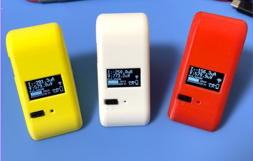
This tool provides a logging function that captures data on voltage, current and power consumption. Voltage input range is from 0 to 35V, maximum current input is 10A.
High-resolution - By using Texas Instruments INA228 IC - 20-bit delta-sigma ADC, it can obtain measurement data with 195µV bus voltage and 163.84mV shunt voltage resolution.
Microcontroller on board - No need for a client PC when measuring. Data is sent directly to the server.
Transfer measurement data via WiFi - This logger can transfer data to a Linux PC via WiFi network and you can view the dashboard graph in InfluxDB.
WPS Support - WiFi credentials can be configured without editing firmware. On first boot (or after a factory reset), the device automatically starts WPS (Push Button Configuration). Press the WPS button on your router within 2 minutes to connect. Credentials are saved to non-volatile storage and reused on subsequent boots.
Calibration Function - Built-in calibration functionality with persistent storage. Long press the center button for 5–10 seconds to perform automatic calibration that corrects voltage and current measurement offsets. Calibration results are automatically saved to non-volatile storage and restored on power-up.
Factory Reset - Long press the center button for 10 seconds or more to erase all saved settings (calibration data, WiFi credentials, etc.) and reboot the device.
Change Channel - This logger allows you to change the measurement channel by pushing the center button with a pin. Once you push the center button, the channel will change to the next channel. The channel cycles through 1, 2, 3, 4, and back to 1.
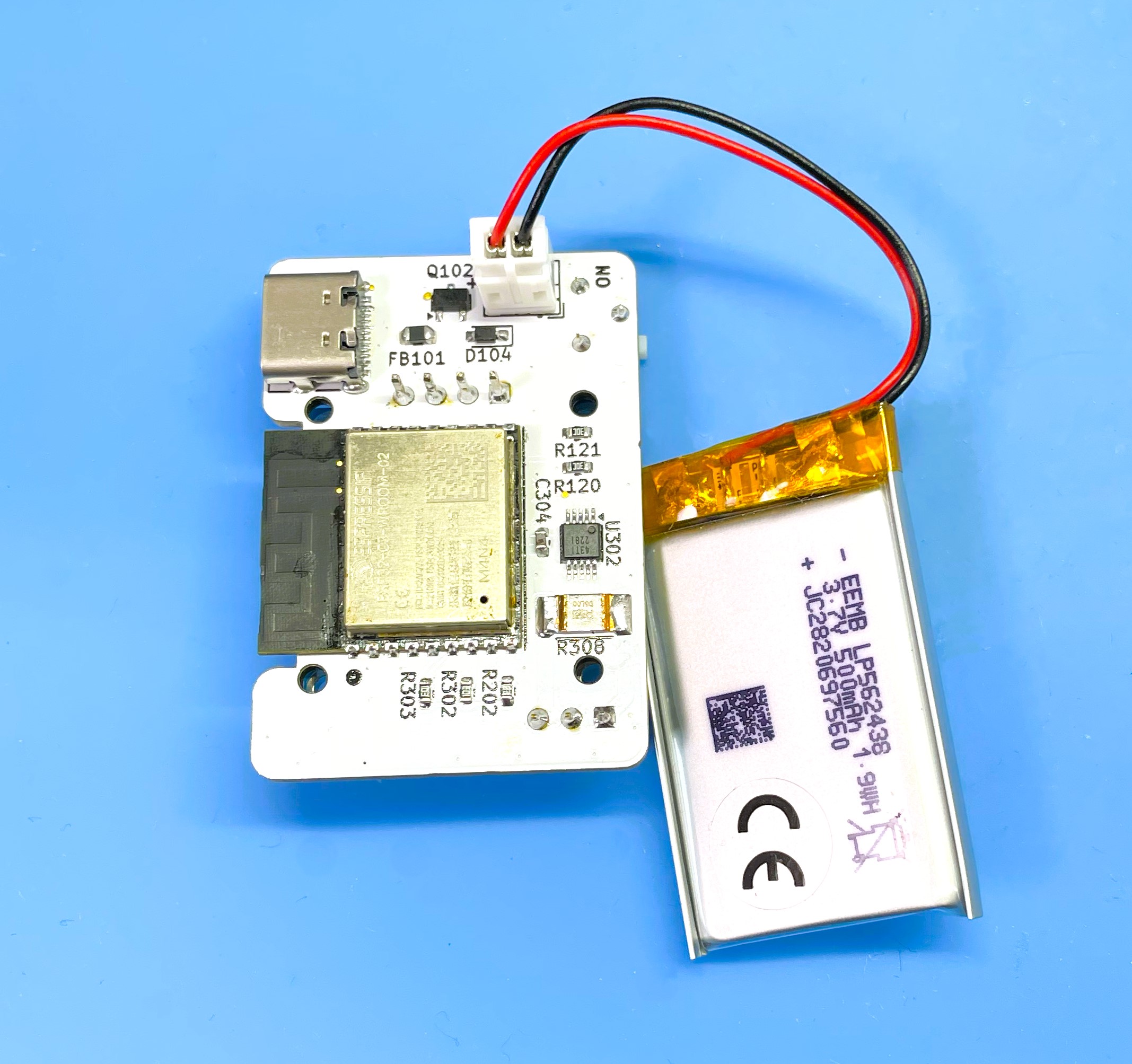
Battery Powered - Uses LiPo battery. It can run for 12 hours on a single charge. The battery is charged via USB Type-C port.
Mini Size - The dimensions are 37mm(W) x 67mm(D) x 55mm(H). It can be used in various locations.
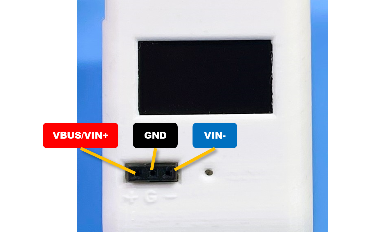
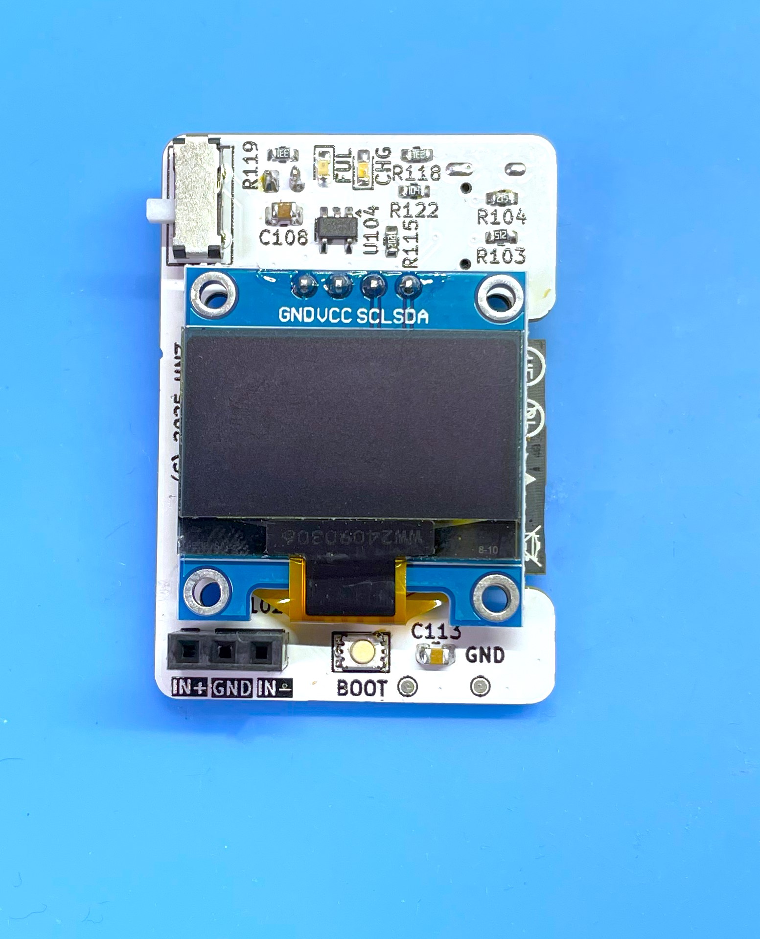
This meter has a pin socket with three pins: VBUS/VIN+, GND, and VIN-. The VBUS/VIN+ pin is connected to the voltage input or the current input. The GND pin is connected to the ground of the voltage or current input. The VIN- pin is connected to the load side of the voltage or current input.
DO NOT CONNECT THE VIN+ AND GND PINS IN REVERSE POLARITY. IF CONNECTED INCORRECTLY, THE ADC IC WILL BE DAMAGED.
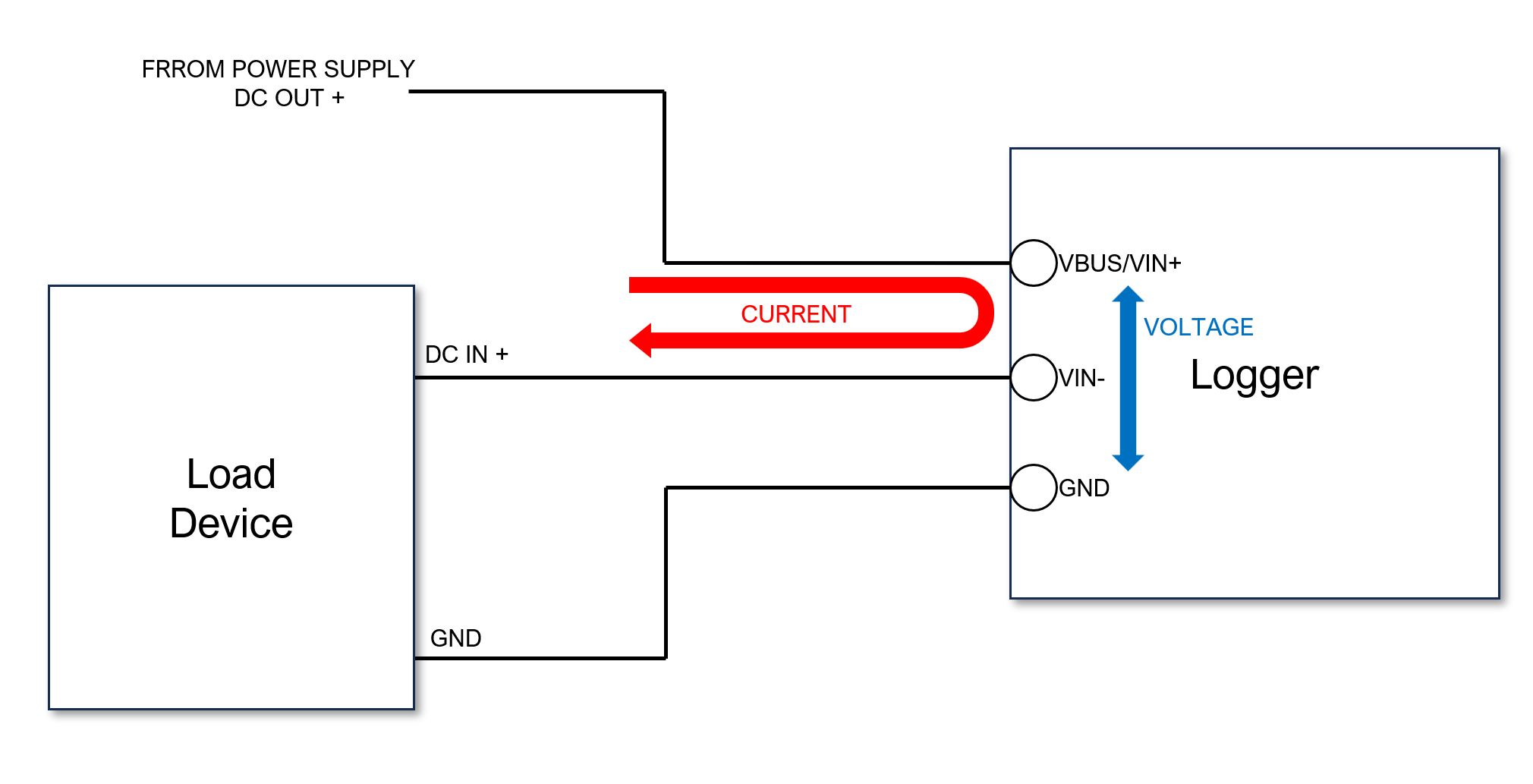
DO NOT CONNECT WITH REVERSE POLARITY BETWEEN VBUS/VIN+ AND GND. IF CONNECTED INCORRECTLY, THE ADC IC WILL BE DAMAGED.
The measurement interval time is fixed at 100ms. Each measurement data is sent to the server every 1 second.
The display shows the current voltage, current, power consumption, battery voltage, buffer consumption, WiFi connection status, and channel number. If the WiFi Access Point cannot establish a connection, the display will not show the WiFi indicator. If voltage is measured while WiFi is not connected, the data is stored in the logger's internal memory buffer. The buffer that is not being sent to the server is indicated by a buffer bar on the display. When the buffer is full (the bar reaches the right edge of the display), measurement stops automatically. When WiFi is connected and data is transmitted to the server, the buffer bar shrinks to the left. When the buffer is full and measurement is stopped, measurement will resume automatically after the buffer drops below 50%.
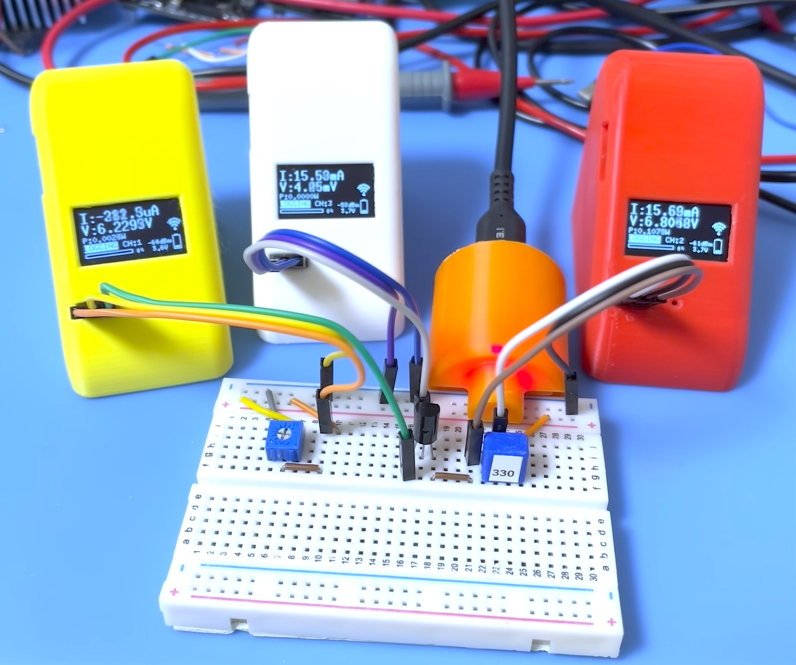
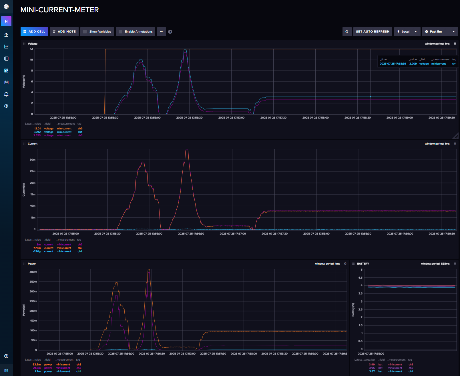
If you send data to the server, you can see real-time data using the Dashboard in InfluxDB. If you have 3 meters, you can view data on the dashboard with different channels simultaneously.
These meters are small and light, so you can use them in various locations. For example, you can use them to measure circuit current on your breadboard, or you can measure the current at each measurement point on your breadboard circuit.
To charge the battery, simply connect to a USB Type-C port from a bus-powered USB port. During charging, the CHG LED is RED. After charging is complete, the FUL LED is GREEN and charging will stop automatically. However,
DO NOT CONTINUE CHARGING IF THE BATTERY IS FULL FOR A LONG TIME.
The Mini Current Meter uses WPS Push Button Configuration (PBC) to connect to a WiFi network without requiring any code changes or configuration files.
WPS... and the device begins WPS negotiation.The saved credentials are loaded from NVS automatically. WPS is skipped and the device connects directly.
To connect to a different access point, perform a Factory Reset (hold the button 10 s+). The stored credentials are erased and WPS runs again on the next boot.
The center button supports three functions depending on how long it is held.
| Hold duration | Action |
|---|---|
| < 5 seconds | Change measurement channel (1 → 2 → 3 → 4 → 1) |
| 5 – 10 seconds | Calibration |
| 10 seconds or more | Factory Reset (erase all NVS data + reboot) |
While holding the button, the display shows a countdown timer and the name of the action that will be triggered when the button is released:
CH x (current channel, no action on release yet)[CALIB] Xs — releasing in this window starts calibration[RESET] Xs — releasing in this window performs factory resetThe Mini Current Meter includes built-in calibration functionality to correct measurement offsets and improve accuracy.
Prepare for calibration: Ensure no current is flowing through the shunt resistor and no voltage is applied to the measurement inputs (VBUS/VIN+ and GND should be at the same potential).
Start calibration: Press and hold the center button for 5–10 seconds. The display shows [CALIB] Xs during this window.
Release the button: Release while the display shows [CALIB] to trigger calibration. Holding beyond 10 seconds switches to factory reset mode.
Calibration process: The device automatically takes 300 samples over 3 seconds to calculate average voltage and current offsets.
Completion: When calibration is complete, the display will show "Calibration OK" for 2 seconds, and the offset values will be automatically saved to non-volatile storage.
Note: Always ensure zero current flow and zero voltage difference during calibration for best results.
Holding the button for 10 seconds or more and releasing it will:
The display shows [RESET] Xs while in this mode. The device boots as if fresh from the factory — WiFi re-provisioning via WPS will be required on first startup.
[CALIB] / [RESET]) while the button is heldUsing Ubuntu 22.04 LTS
sudo apt update && sudo apt -y install git python3 python3-pip gcc build-essential curl pkg-config libudev-dev libtinfo5 clang libclang-dev llvm-dev udev libssl-dev python3.10-venv
curl --proto '=https' --tlsv1.2 -sSf https://sh.rustup.rs | sh
select No.1
After installation, you need to set the environment variable for Rust.
Add the following line to your shell configuration file (e.g., ~/.bashrc, ~/.zshrc, etc.):
source "$HOME/.cargo/env"cargo install ldproxy
cargo install espup
cargo install cargo-espflashAt this time (2025-07-25), espup cannot be compiled. If you get an error, please use the following command to install the toolchain.
cargo install cargo-binstall
cargo binstall espupespup install
espup updateThen, run the following command to set the environment for the ESP32-C3 toolchain:
. ./export-esp.shsudo sh -c 'echo "SUBSYSTEMS==\"usb\", ATTRS{idVendor}==\"303a\", ATTRS{idProduct}==\"1001\", MODE=\"0666\"" > /etc/udev/rules.d/99-esp32.rules'
sudo udevadm control --reload-rules
sudo udevadm triggergit clone https://github.com/hnz1102/mini-current-meter.git
cd mini-current-meter/codeYou need to set the WiFi SSID, password, and InfluxDB server IP address in the configuration file.
You can find the configuration file 'cfg.toml.samp' in the code directory. You need to copy this file to cfg.toml and edit it.
nano code/cfg.toml

[mini-current-meter]
wifi_ssid = "XXXXXXXXXXXX"  # Set your WiFi SSID.
wifi_psk = "XXXXXXXXXXXXX"  # Set your WiFi Password.
shunt_resistance = "0.005"
influxdb_server = "<IP Address>:8086"  # Set your InfluxDB server IP address.
influxdb_api_key = "<API_KEY>" # Set your InfluxDB API Key.
influxdb_api = "/api/v2/write?org=<ORG>&bucket=LOGGER&precision=ns" # Set your InfluxDB API URL. You must set <ORG> same as Initial Organization Name.
influxdb_tag = "ch"
influxdb_measurement = "minicurrent"
max_records = "1023"Connect the mini-current-meter via USB to this build code PC. Then,
$ cargo espflash board-info
select /dev/ttyACM0
Chip type: esp32c3 (revision v0.4)
Crystal frequency: 40MHz
Flash size: 4MB
Features: WiFi, BLE
MAC address: xx:xx:xx:xx:xx:xx
$ rustup component add rust-src --toolchain nightly-2023-06-10-x86_64-unknown-linux-gnu$ cargo espflash flash --release --monitor
App/part. size: 964,240/3,145,728 bytes, 30.23%
[00:00:00] [========================================] 12/12 0x0
[00:00:00] [========================================] 1/1 0x8000
[00:00:11] [========================================] 546/546 0x10000 [2023-11-11T10:17:05Z INFO ] Flashing has completed!
Automatically boots!$ wget https://dl.influxdata.com/influxdb/releases/influxdb2-2.7.0-amd64.deb
$ sudo dpkg -i influxdb2-2.7.0-amd64.deb
$ sudo service influxdb startConnect to 'http://<InfluxDB installed PC Address>:8086'Click GET STARTED and set Username, Password, Initial Organization Name, and Initial Bucket Name
| Term | Value |
|---|---|
| Username | Set login username as InfluxDB administrator web console |
| Password | Set login password as InfluxDB administrator web console |
| Initial Organization Name | Organization Name ex. ORG |
| Initial Bucket Name | LOGGER |
After setting these, click CONTINUE.
You can see the operator API token in the browser. YOU WON'T BE ABLE TO SEE IT AGAIN!
If you want to get a new API token, click API Tokens menu from Sources Icon, then click GENERATE API TOKEN and select All access token, click Save.
You can see the new API token and copy it.
After copying the token, click CONFIGURE LATER.
Click the Dashboard icon, and select Import Dashboard from the CREATE DASHBOARD menu.
Drop the mini-current-meter/dashboard/mini-current-meter.json file to Drop a file here, then click IMPORT JSON AS DASHBOARD.
You can see the Mini Current Meter Dashboard panel on the Dashboards page.
Click this panel, and you can see the Mini Current Meter Dashboard.
If you want to customize the dashboard design, click the configure mark. You can change the graph design.
Turn on the power switch. Logging data will be sent to InfluxDB. You can see the data on the dashboard.
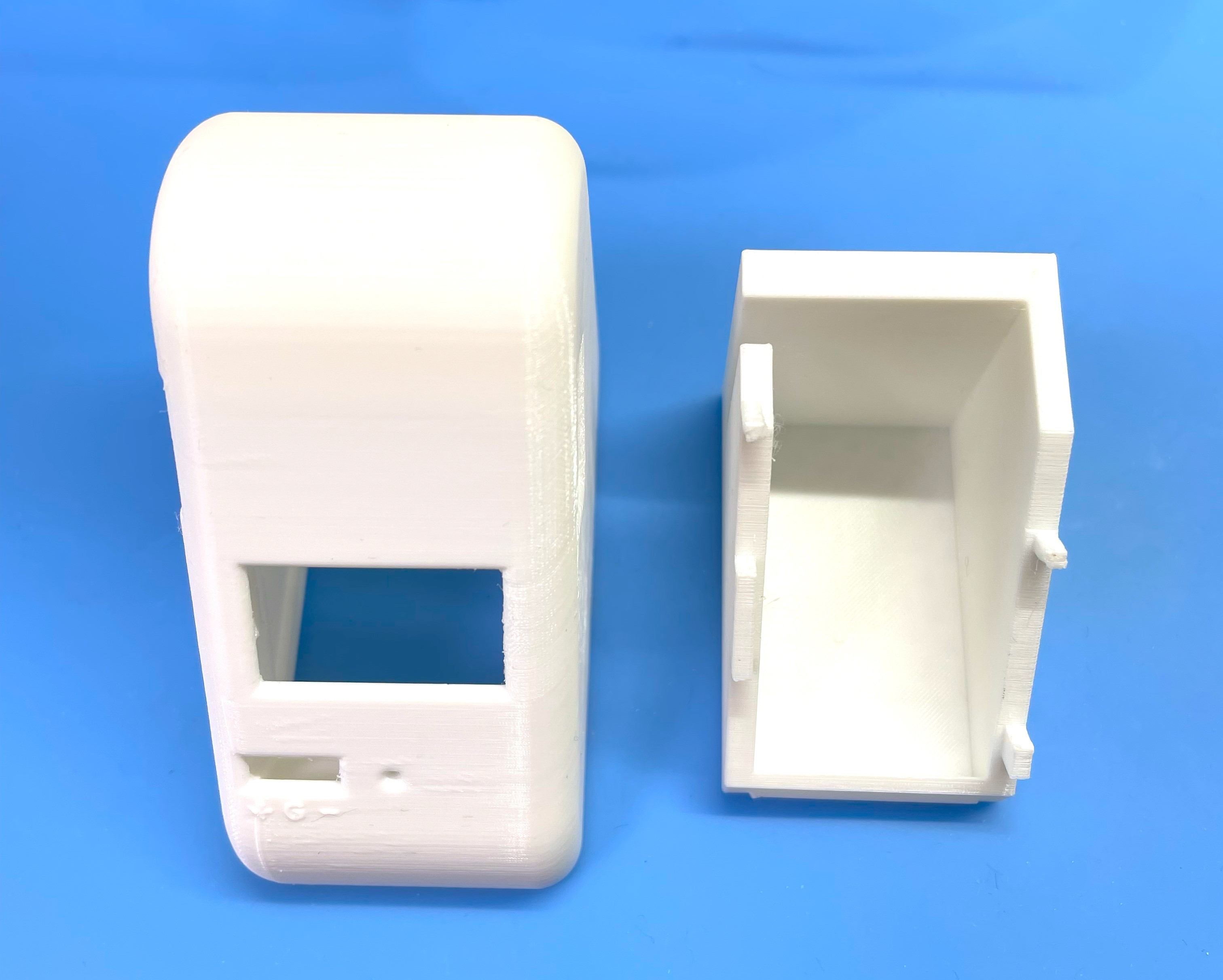
There is schematic data in the hardware directory including 3D printing data as 3MF format files.
This source code is licensed under MIT. Other Hardware Schematic documents are licensed under CC-BY-SA V4.0.
| Qty | Value | Footprint | References |
|---|---|---|---|
| 6 | 10K | Resistor_SMD:R_0603_1608Metric | R108, R110, R202, R302, R303, R304 |
| 3 | 20K 1% | Resistor_SMD:R_0603_1608Metric | R106, R120, R121 |
| 2 | 0.1uF | Capacitor_SMD:C_0603_1608Metric | C111, C304 |
| 2 | 1uF | Capacitor_SMD:C_0805_2012Metric | C109, C113 |
| 2 | 330 | Resistor_SMD:R_0603_1608Metric | R118, R119 |
| 2 | 5.1K | Resistor_SMD:R_0603_1608Metric | R103, R104 |
| 1 | 100K | Resistor_SMD:R_0603_1608Metric | R122 |
| 1 | 10uF | Capacitor_SMD:C_0805_2012Metric | C112 |
| 1 | 12K 1% | Resistor_SMD:R_0603_1608Metric | R107 |
| 1 | 2K | Resistor_SMD:R_0603_1608Metric | R115 |
| 1 | 3.5x2.6 Tact SW | tbctl:WS-TASV SMT Tact Switch | SW201 |
| 1 | 4.7uF | Capacitor_SMD:C_0805_2012Metric | C108 |
| 1 | 5m | Resistor_SMD:R_2512_6332Metric_Pad1.40x3.35mm_HandSolder | R308 |
| 1 | BOOT | TestPoint:TestPoint_Pad_D1.0mm | TP202 |
| 1 | Conn_01x03 | Connector_PinSocket_2.54mm:PinSocket_1x03_P2.54mm_Vertical | J102 |
| 1 | ESP32-C3-WROOM-02-N4 | tbctl:IC18_ESP32-C3-WROOM-02-N4_EXP | U101 |
| 1 | GND | TestPoint:TestPoint_Pad_D1.0mm | TP101 |
| 1 | INA228 | Package_SO:VSSOP-10_3x3mm_P0.5mm | U302 |
| 1 | LED GREEN | LED_SMD:LED_0603_1608Metric_Pad1.05x0.95mm_HandSolder | D103 |
| 1 | LED RED | LED_SMD:LED_0603_1608Metric_Pad1.05x0.95mm_HandSolder | D102 |
| 1 | LiPo BATTERY | Connector_JST:JST_PH_B2B-PH-K_1x02_P2.00mm_Vertical | J103 |
| 1 | MCP73831-2-OT | Package_TO_SOT_SMD:SOT-23-5 | U104 |
| 1 | MH2029-601Y | Inductor_SMD:L_0805_2012Metric | FB101 |
| 1 | NSR0340HT1G | Diode_SMD:D_SOD-323_HandSoldering | D104 |
| 1 | SLIDE_SW | tbctl:SLIDE_SW_IS1235-G | SW105 |
| 1 | SPX3819M5-L | Package_TO_SOT_SMD:SOT-23-5 | U102 |
| 1 | SSD1306_DISPLAY | tbctl:OLED I2C DISPLAY | U103 |
| 1 | SSM3J332R | Package_TO_SOT_SMD:SOT-23 | Q102 |
| 1 | USB4105-GF-A | tbctl:USB_C_5077CR-16-SMC2-BK-TR | J101 |


hnz1102/EEW-display
ESP32-S3 firmware for a small earthquake-information display. It shows recent earthquakes and emergency earthquake warnings (緊急地震速報, EEW) from [P2P地震情報](https://www.p2pquake.net/), draws the epicenters on a Google map…


hnz1102/current-logger
This tool provides a logging function that gets data on voltage, current and power consumption. Voltage input range is from 0 to 85V, Maximum current input is 15A.

hnz1102/temp-logger
Logging Thermocouple Temperature and Send Data to InfluxDB system.

hnz1102/mini-power
Mini-Power is a small, portable DC power supply unit designed to provide a convenient and reliable source of adjustable voltage for your electronic devices and breadboard experiments.

hnz1102/ssh-serial-bridge
Firmware for the ESP32-S3 that bridges an SSH connection (over Wi-Fi) to UART and USB CDC serial ports. Written in Rust (esp-idf-hal / esp-idf-svc) with a C component (wolfSSH) for the SSH server.
It measures 30 × 43 mm and has 2 copper layers, 1.6 mm thick.
40 parts, built around the ESP32-C3-WROOM-02-N4, SPX3819M5-L, MH2029-601Y and NSR0340HT1G-HXY. The full list of its parts is on this page, with links to each part's symbol and footprint where PCBKit's library has them.
From the hnz1102/mini-current-meter repository on GitHub, at the commit this page was made from: the board is hardware/currentmeter.kicad_pcb and its schematic hardware/currentmeter.kicad_sch. PCBKit opens the board in the browser, with nothing to install.
Its repository states no licence, so its author keeps all rights: ask hnz1102 before reusing the design.