2 layers30 × 43 mm
Currentmeter
hnz1102/mini-current-meter
Mini Current Meter using INA228A ultra-precise digital power monitor
40 parts10

 hnz1102/wakepcbox4
Wake on LAN Controller Box
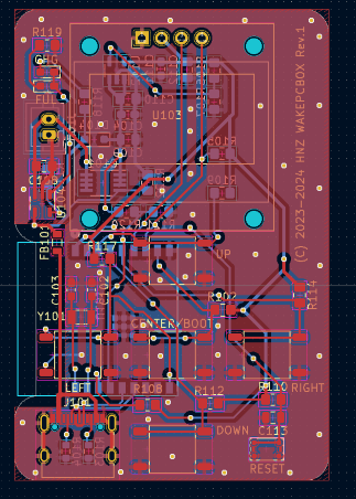
Wakepc is an open-source printed circuit board by hnz1102, from the hnz1102/wakepcbox repository on GitHub. It is a 2-layer board of 40 × 60 mm with 45 parts on 33 nets, routed with 306 tracks and 86 vias.
It is built around the ESP32-C3-WROOM-02-N4, SPX3819M5-L and IRF7606TRPBF, with the MH2029-601Y, NSR0340HT1G-HXY and USB4105-GF-A among its other parts. Its parts include 18 resistors, 9 capacitors, 6 switches, 4 ICs and 3 diodes. It belongs with the radio and wireless boards and the ESP32 and RISC-V boards of this library.


Wake PC Box
Video
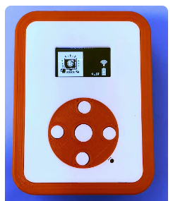
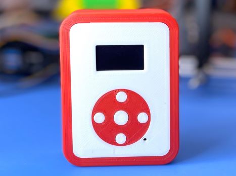
This is the small control box that can wake up the PC using Wake On LAN. You can just push a button, PCs will wake up from the power off status. There is no need to start up another PC in order to start up a PC with Wake On Lan. Wake on LAN packets are sent via WiFi LAN. The Box has a battery, and you can charge it from a USB Type-C port. Once charging full, you can use it for a month. If any buttons are not pressed for the specified time (default 30 seconds), the box will sleep automatically and conserve battery power. Up to four PCs can be registered.
This box can send a Wake on LAN packet to the Wireless Access Point. To transfer the packet, the Access Point needs to be set to Bridge Mode. If Router Mode is set, the Access Point won't transfer to the wired LAN.
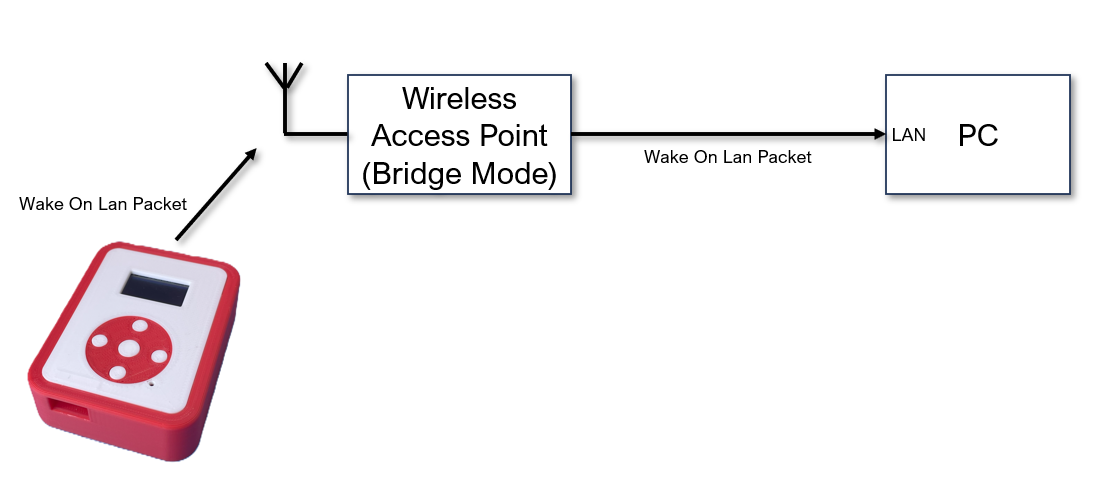
Quick Wake Up - Simply press one of the up, down, left, or right buttons to turn on the PC corresponding to that button. 4 PCs can be registered.
Microcontroller on board - No need for a PC when you turn on another PC. Directly send packets to the target PCs.
Transmit a packet via WiFi - Wake-on LAN packets are transmitted via Wireless Network.
Battery Powered - Using LiPo battery. It can run for a month (In this case, every day a few times used).
Small Handy Box - This box is only 60mm(W) x 23mm(H) x 80mm(D) size. No need for any cables, it works.
Configurable - Setting parameters are set from the display menu. SSID/Password/Target PC Hardware Address(4 PCs)/Time Zone/Sleep Time/Sleep Mode/Display Off Time/Reset Settings.
WPS Support - If wps_enable = "true" and wifi_ssid is empty in cfg.toml, the device enters WPS PBC (Push Button Configuration) mode on first boot. Press the WPS button on your router within 120 seconds. The obtained SSID and password are saved to NVS automatically, and subsequent boots connect normally without WPS.
At first, you can set the WiFi SSID and PSK-Password in one of two ways:
Option A: Manual entry via menu - Push the Center Key to open the setting menu, select WiFi, then enter your SSID and password using the direction keys.
Option B: WPS PBC mode - Set wps_enable = "true" and leave wifi_ssid empty in cfg.toml before flashing. On first boot, the device displays "WPS MODE" and waits up to 120 seconds. Press the WPS button on your router to transfer the credentials automatically. The SSID and password are saved and WPS mode is disabled for subsequent boots.
Next, set the Hardware Address(Ethernet MAC Address) of the PC that you want to wake up. Select HW Address and push Center Key, select from PC1 to PC4, push Center key, then enter your Hardware Address like 00:11:22:33:44:55.
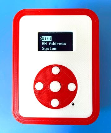
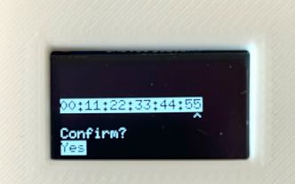
After setting, just push button corresponding the target.(Up Key : PC1, Down Key : PC2, Left Key: PC3, Right Key: PC4)
To charge a battery, just connect to a USB Type-C port from the bus-powered USB port. During the charge, the CHG LED is RED ON. After the charging is full, the FUL LED is GREEN ON. And the charging will be stopped automatically.
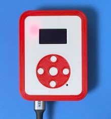
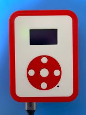
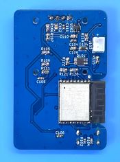
Assembled PCB
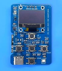
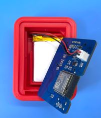
Set in Box
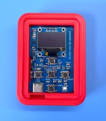
Using Ubuntu 22.04.3 LTS and ESP-IDF V5.4.2
sudo apt update && sudo apt -y install git python3 python3-pip gcc build-essential curl pkg-config libudev-dev libtinfo5 clang libclang-dev llvm-dev udev libssl-dev python3.10-venv
curl --proto '=https' --tlsv1.2 -sSf https://sh.rustup.rs | sh
You can see the install menu, select No.1. After installation, set the environment variable.
. "$HOME/.cargo/env"cargo install ldproxy
cargo install espup
cargo install cargo-espflashespup install
espup updateThen, run the following command to set the environment for the ESP32-C3 toolchain:
. ./export-esp.shsudo sh -c 'echo "SUBSYSTEMS==\"usb\", ATTRS{idVendor}==\"303a\", ATTRS{idProduct}==\"1001\", MODE=\"0666\"" > /etc/udev/rules.d/99-esp32.rules'
sudo udevadm control --reload-rules
sudo udevadm triggergit clone https://github.com/hnz1102/wakepcbox.git
cd wakepcboxcfg.toml
[wakepcbox]
wifi_ssid = "<SSID>" # Set your AP SSID. Leave empty to use WPS mode.
wifi_psk = "<Password>" # Set password for SSID.
wps_enable = "false" # Set "true" to use WPS PBC mode on first boot (requires wifi_ssid to be empty).
target_mac_address1 = "00:00:00:00:00:00" # Set Hardware Address(MAC Address) for wakeup.
target_mac_address2 = "00:00:00:00:00:00"
target_mac_address3 = "00:00:00:00:00:00"
target_mac_address4 = "00:00:00:00:00:00"
timezone_offset = "0"
idle_in_sleep_time = "30"
sleep_mode = "light"
display_off_time = "30"
wakeup_interval = "10"cargo build --releaseConnecting the Box by USB Type-C to this code building PC. Then,
cargo espflash board-info

✔ Use serial port '/dev/ttyACM0' - USB JTAG/serial debug unit? · yes
✔ Remember this serial port for future use? · yes
[2026-02-14T04:41:35Z INFO ] Serial port: '/dev/ttyACM0'
[2026-02-14T04:41:35Z INFO ] Connecting...
[2026-02-14T04:41:36Z INFO ] Using flash stub
Chip type:         esp32c3 (revision v0.4)
Crystal frequency: 40 MHz
Flash size:        4MB
Features:          WiFi, BLE
MAC address:       a0:76:4e:b3:64:c0

Security Information:
=====================
Flags: 0x00000000 (0)
Key Purposes: [0, 0, 0, 0, 0, 0, 12]
Chip ID: 5
API Version: 3
Secure Boot: Disabled
Flash Encryption: Disabled
SPI Boot Crypt Count (SPI_BOOT_CRYPT_CNT): 0x0cargo espflash flash --release --monitor
[2026-02-14T04:43:53Z INFO ] Serial port: '/dev/ttyACM0'
[2026-02-14T04:43:53Z INFO ] Connecting...
[2026-02-14T04:43:53Z INFO ] Using flash stub
Compiling wakepcbox v0.1.0 (/wakepcbox)
Finished `release` profile [optimized] target(s) in 4.22s
Chip type: esp32c3 (revision v0.4)
Crystal frequency: 40 MHz
Flash size: 4MB
Features: WiFi, BLE
MAC address: a0:76:4e:b3:64:c0
App/part. size: 1,644,080/3,145,728 bytes, 52.26%
[00:00:00] [========================================] 13/13 0x0 Verifying... OK! [00:00:00] [========================================] 1/1 0x8000 Skipped! (checksum matches)
[00:00:15] [========================================] 887/887 0x10000 Verifying... OK! [2026-02-14T04:44:16Z INFO ] Flashing has completed!
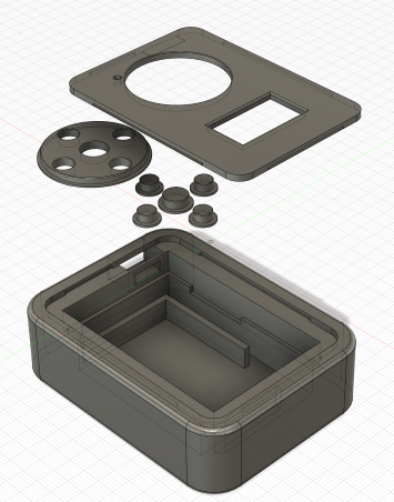
And automatically boot!There is a Schematic data in the hardware directory including 3D printing data.
This source code is licensed under MIT. Other Hardware Schematic documents are licensed under CC-BY-SA V4.0.
| Qty | Value | Footprint | References |
|---|---|---|---|
| 6 | 10K | Resistor_SMD:R_0805_2012Metric_Pad1.20x1.40mm_HandSolder | R102, R109, R110, R112, R114, R117 |
| 5 | TS-06104 | Library:TS-06104 | SW101, SW103, SW104, SW105, SW106 |
| 3 | 20K 1% | Resistor_SMD:R_0805_2012Metric_Pad1.20x1.40mm_HandSolder | R106, R120, R121 |
| 2 | 0.1uF | Capacitor_SMD:C_0603_1608Metric_Pad1.08x0.95mm_HandSolder | C104, C111 |
| 2 | 10K | Resistor_SMD:R_0603_1608Metric | R105, R108 |
| 2 | 10uF | Capacitor_SMD:C_0805_2012Metric_Pad1.18x1.45mm_HandSolder | C110, C112 |
| 2 | 16pF | Capacitor_SMD:C_0603_1608Metric_Pad1.08x0.95mm_HandSolder | C102, C103 |
| 2 | 1uF | Capacitor_SMD:C_0805_2012Metric | C109, C113 |
| 2 | 330 | Resistor_SMD:R_0805_2012Metric_Pad1.20x1.40mm_HandSolder | R118, R119 |
| 2 | 5.1K | Resistor_SMD:R_0603_1608Metric | R103, R104 |
| 1 | 100K | Resistor_SMD:R_0805_2012Metric_Pad1.20x1.40mm_HandSolder | R122 |
| 1 | 12K 1% | Resistor_SMD:R_0805_2012Metric_Pad1.20x1.40mm_HandSolder | R107 |
| 1 | 2K | Resistor_SMD:R_0805_2012Metric_Pad1.20x1.40mm_HandSolder | R115 |
| 1 | 3.5x2.6 Tact SW | Library:WS-TASV SMT Tact Switch | SW102 |
| 1 | 32.7680KHz | Crystal:Crystal_SMD_3215-2Pin_3.2x1.5mm | Y101 |
| 1 | 4.7uF | Capacitor_SMD:C_0805_2012Metric_Pad1.18x1.45mm_HandSolder | C108 |
| 1 | ESP32-C3-WROOM-02-N4 | Library:IC18_ESP32-C3-WROOM-02-N4_EXP | U101 |
| 1 | IRF7606TRPBF | Package_SO:MSOP-8_3x3mm_P0.65mm | Q101 |
| 1 | LED GREEN | LED_SMD:LED_0603_1608Metric_Pad1.05x0.95mm_HandSolder | D103 |
| 1 | LED RED | LED_SMD:LED_0603_1608Metric_Pad1.05x0.95mm_HandSolder | D102 |
| 1 | LiPo BATTERY | Connector_JST:JST_PH_B2B-PH-K_1x02_P2.00mm_Vertical | J103 |
| 1 | MCP73831-2-OT | Package_TO_SOT_SMD:SOT-23-5 | U104 |
| 1 | MH2029-601Y | Inductor_SMD:L_0805_2012Metric | FB101 |
| 1 | NSR0340HT1G | Diode_SMD:D_SOD-323_HandSoldering | D104 |
| 1 | SPX3819M5-L | Package_TO_SOT_SMD:SOT-23-5 | U102 |
| 1 | SSD1306_DISPLAY | Library:OLED I2C DISPLAY | U103 |
| 1 | USB4105-GF-A | Library:USB_C_5077CR-16-SMC2-BK-TR | J101 |
It measures 40 × 60 mm and has 2 copper layers, 1.6 mm thick.
45 parts, built around the ESP32-C3-WROOM-02-N4, SPX3819M5-L, IRF7606TRPBF and MH2029-601Y. The full list of its parts is on this page, with links to each part's symbol and footprint where PCBKit's library has them.
From the hnz1102/wakepcbox repository on GitHub, at the commit this page was made from: the board is hardware/wakepc.kicad_pcb and its schematic hardware/wakepc.kicad_sch. PCBKit opens the board in the browser, with nothing to install.
Its repository states no licence, so its author keeps all rights: ask hnz1102 before reusing the design.
hnz1102/mini-current-meter
Mini Current Meter using INA228A ultra-precise digital power monitor

hnz1102/temp-logger
Logging Thermocouple Temperature and Send Data to InfluxDB system.

hnz1102/current-logger
This tool provides a logging function that gets data on voltage, current and power consumption. Voltage input range is from 0 to 85V, Maximum current input is 15A.


hnz1102/EEW-display
ESP32-S3 firmware for a small earthquake-information display. It shows recent earthquakes and emergency earthquake warnings (緊急地震速報, EEW) from [P2P地震情報](https://www.p2pquake.net/), draws the epicenters on a Google map…


hnz1102/sdcdmux-emmc
SD CARD and eMMC Device Multiplexer with Infrared Remote Controller

hnz1102/mini-power
Mini-Power is a small, portable DC power supply unit designed to provide a convenient and reliable source of adjustable voltage for your electronic devices and breadboard experiments.