2 layers50 × 70 mm
Temp logger
hnz1102/temp-logger
Logging Thermocouple Temperature and Send Data to InfluxDB system.
52 parts5

 hnz1102/current-logger18
This tool provides a logging function that gets data on voltage, current and power consumption. Voltage input range is from 0 to 85V, Maximum current input is 15A.
Current logger is an open-source printed circuit board by hnz1102, from the hnz1102/current-logger repository on GitHub. It is a 2-layer board of 91.7 × 70 mm with 64 parts on 62 nets, routed with 636 tracks and 189 vias.
It is built around the ESP32-C3-WROOM-02-N4, SPX3819M5-L and BK2125HS601-T, with the NSR0340HT1G-HXY among its other parts. Its parts include 24 resistors, 14 connectors, 9 capacitors, 5 ICs and 5 switches. It belongs with the ESP32 and RISC-V boards of this library.


Voltage-Current Logger
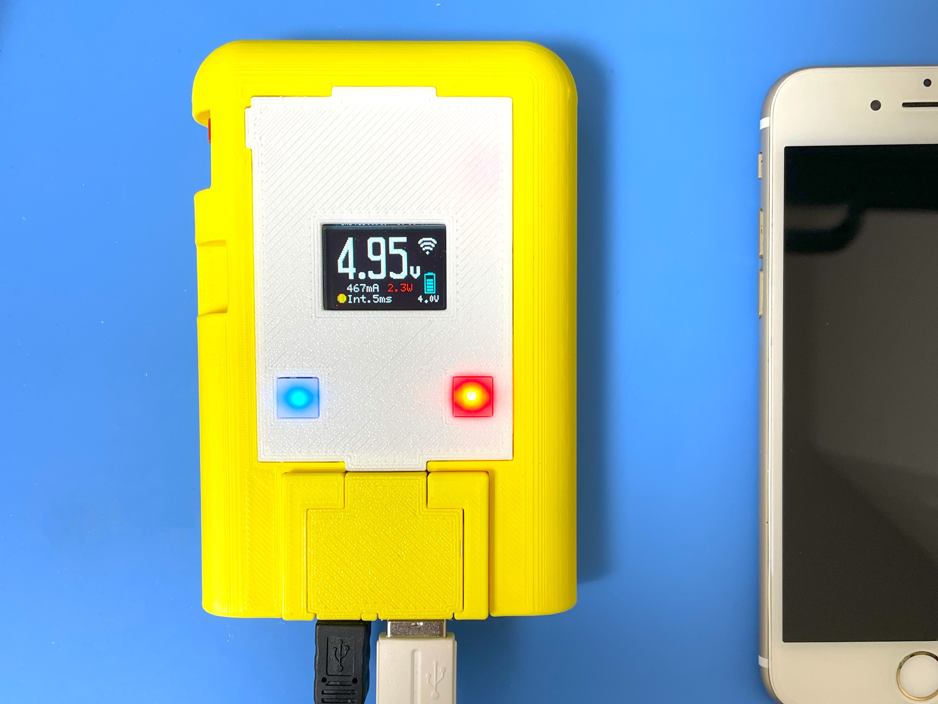
This tool provides a logging function that gets data on voltage, current and power consumption. Voltage input range is from 0 to 85V, Maximum current input is 15A.
High-resolution - By using Texas Instruments INA228 IC - 20-bit delta-sigma ADC, It can be got measurement data with 195.uV Bus voltage and 163.84mV Shunt voltage.
Microcontroller on board - No need for a client PC when you are measuring. Directly send to the server.
Transfer measurement data via WiFi - This Logger can transfer data to Linux PC via WiFi network and you can see the dashboard graph in influxDB.
Battery Powered - Using LiPo battery. It can run for 24-48 hours.
Multiple Adopter - This Logger can be changed 4 type adopters (USB-Type-C-Type-C, USB-Type-A-mini Type-B, JST-PH-Connector for Battery, 3P-Terminal)
This logger has four types of adapters, and by changing them, it is possible to measure the usage voltage, current, and power consumption of various devices"
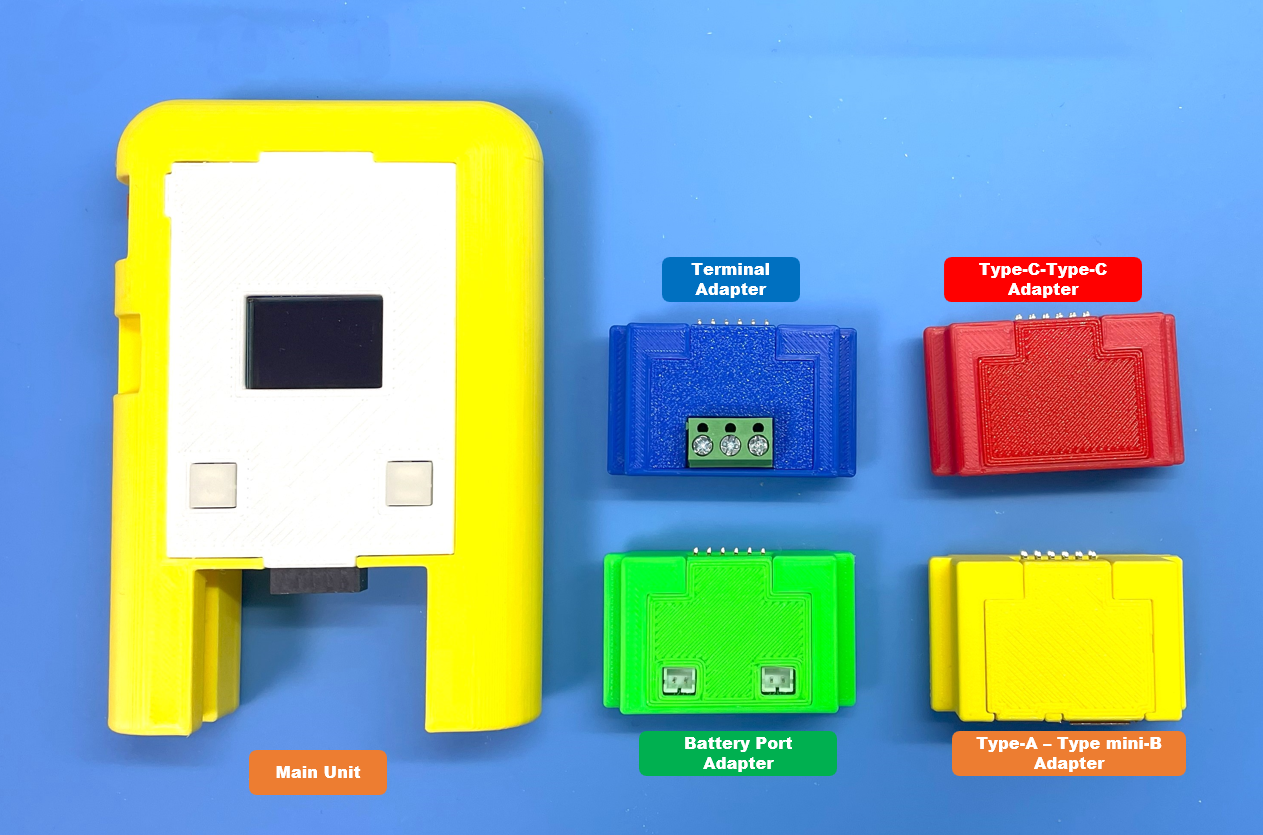
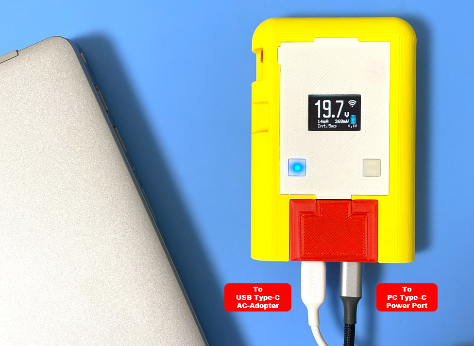
Red Adapter - To measure the voltage and current from USB Type-C Power Adapter to Type-C Power Input Device(PCs, etc.)
Yellow Adapter - To measure the voltage and current from USB Type mini-B port to USB Type-A output port.
Green Adapter - To measure the voltage and current between JST-PH connector. (Batteries, etc.)
Blue Adapter - To measure the voltage and current some cabling type.
For example, if you want to measure the voltage of USB-Type-C power, set the red adopter into the slot. If the power supply does not work, you can try to insert one of the connected Type-C connections in the opposite side of the back. Because a Type-C cable has two sides.
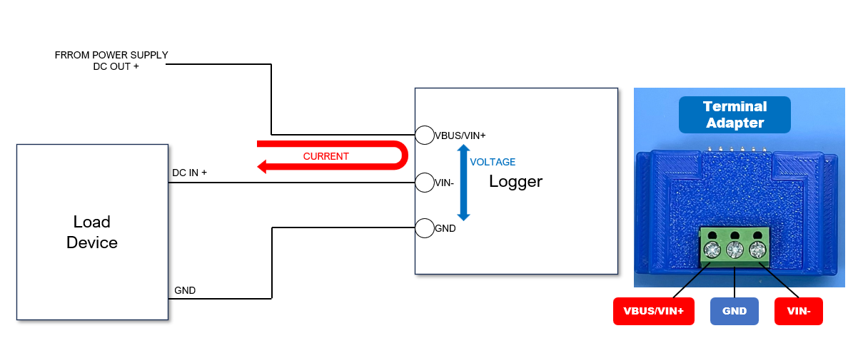
The Blue Adapter has 3 pins screw terminal. To measure voltage and current, connect to the following the schematic.
DO NOT CONNECT WITH OPPOSITE POLARITY. IF CONNECTED, THE ADC IC IS WILL BE DAMAGED.
The measurement interval time can be selected from 5 ms to 1 sec. When the logger is powered on, the interval time is 5 ms, then pressing the INT button will set the interval to 10, 50, 100, 500ms, or 1 sec. Push the START button, then the logger starts to send to the server voltage, current and power consumption data.
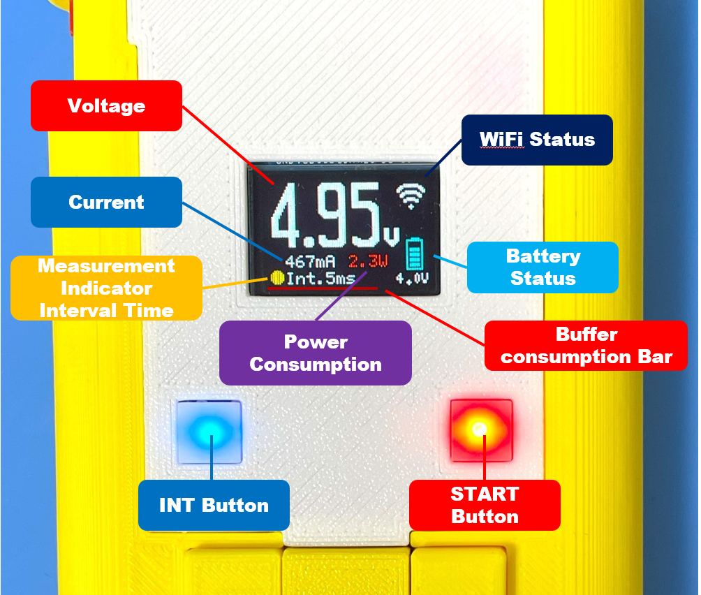
A display can show you the current voltage, current, power consumption, battery voltage, buffer consumption, and WiFi connection status. If the WiFi Access Point cannot establish a connection, the display will not show WiFi mark. If voltage is measured while the WiFi is not connected, the data is stored in the logger's internal memory buffer. The buffer that is not being sent to the server is indicated by a red bar line on the display. When the buffer is full (the line reaches the right edge of the display), the measurement stops automatically. Then, when the WiFi is connected and transmitted to the server, the buffer line shrinks to the left. If the buffer is full and the measurement is stopped, pressing the Start button again discards the measurement data being held and starts the measurement again.
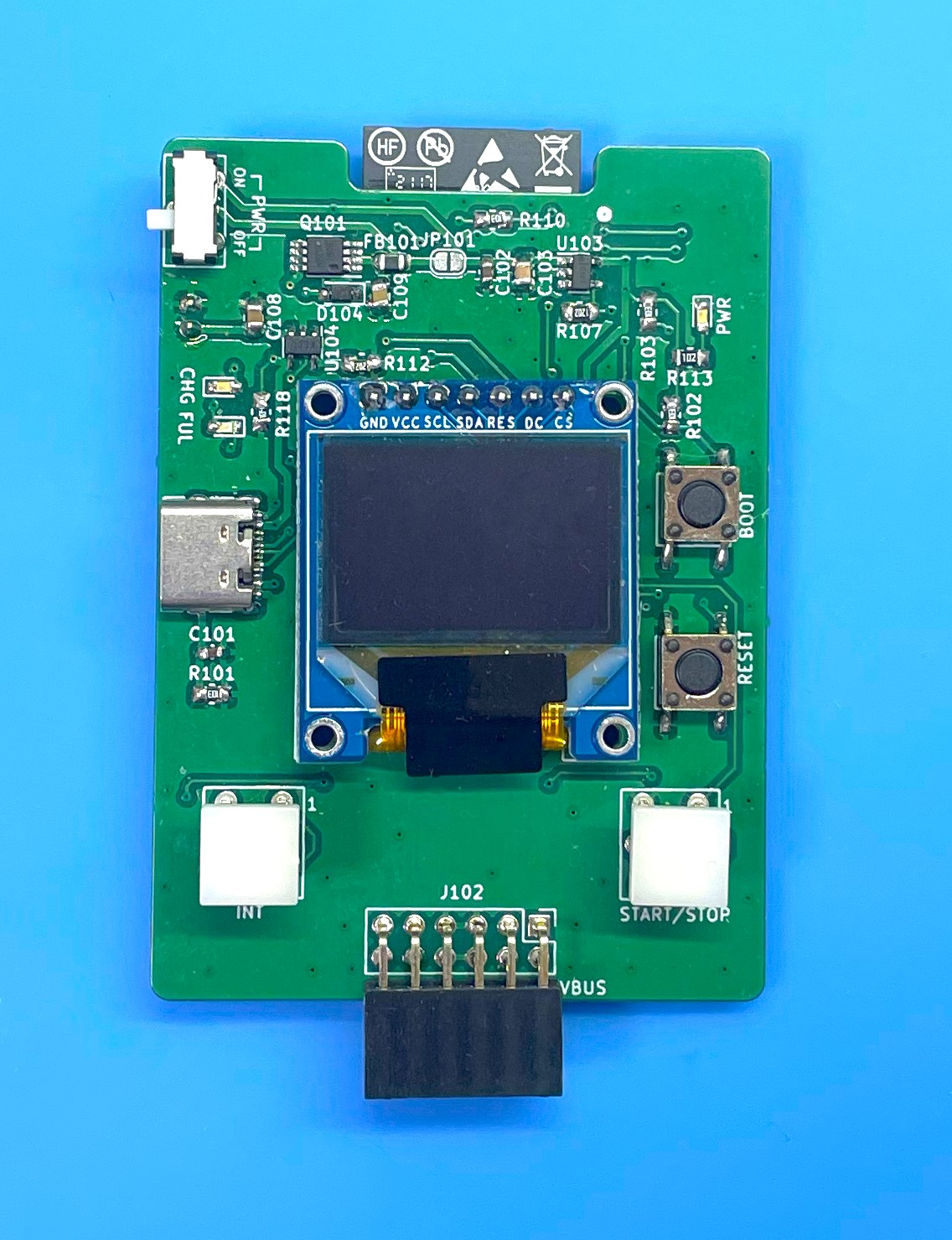
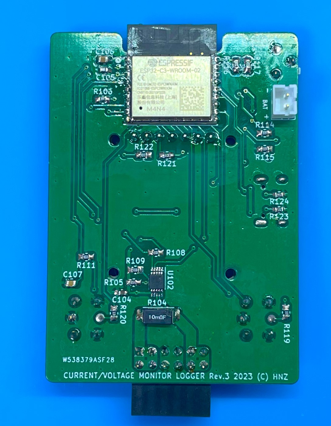
If you send data to the server, You can see the realtime data using Dashboard by InfluxDB.
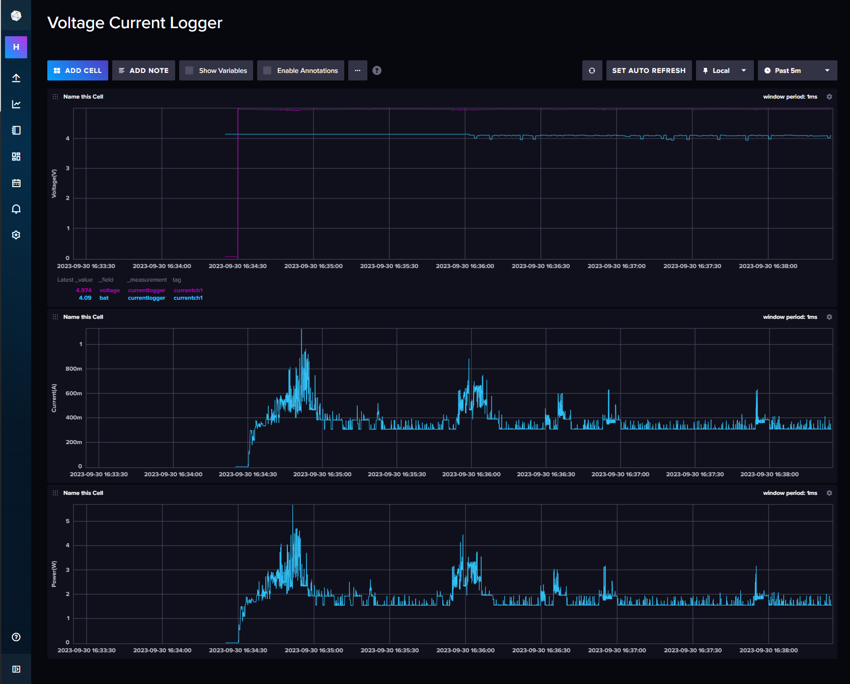
After the measure, to stop logging, push the START button again.
To charge a battery, just connect to a USB Type-C port from the bus-powered USB port. During the charge, the CHG LED is RED ON. After the charging is full, the FUL LED is GREEN ON. And the charging will be stopped automatically. But,
DO NOT CONTINUE THE CHARGE IF THE BATTERY IS FULL FOR A LONG TIME.
Using Ubuntu 22.04.03 LTS
$ sudo apt -y install git python3 python3-pip gcc build-essential curl pkg-config libudev-dev libtinfo5 clang libclang-dev llvm-dev udev
$ curl --proto '=https' --tlsv1.2 -sSf https://sh.rustup.rs | sh
select No.1
$ source "$HOME/.cargo/env"$ cargo install ldproxy
$ cargo install espup
$ rustup toolchain install nightly --component rust-src
$ rustup target add riscv32imc-unknown-none-elf
$ cargo install cargo-espflash$ sudo sh -c 'echo "SUBSYSTEMS==\"usb\", ATTRS{idVendor}==\"303a\", ATTRS{idProduct}==\"1001\", MODE=\"0666\"" > /etc/udev/rules.d/99-esp32.rules'
$ sudo udevadm control --reload-rules
$ sudo udevadm trigger$ git clone https://github.com/hnz1102/current-logger.git
$ cd current-logger/src/current-loggersrc\current-logger\cfg.toml
[currentlogger]
wifi_ssid = "<your-AP-ssid>" # Set your AP ssid.
wifi_psk = "<your-AP-Password>" # Set password for ssid
http_server = "<PC address>:3001" # Set IP address and port. port should be 3001.Connecting the current-Logger by USB to this build code PC. Then,
$ cargo espflash board-info
select /dev/ttyACM0
Chip type: esp32c3 (revision v0.4)
Crystal frequency: 40MHz
Flash size: 4MB
Features: WiFi, BLE
MAC address: xx:xx:xx:xx:xx:xx
$ rustup component add rust-src --toolchain nightly-2023-06-10-x86_64-unknown-linux-gnu$ cargo espflash flash --release --monitor
App/part. size: 964,240/3,145,728 bytes, 30.23%
[00:00:00] [========================================] 12/12 0x0
[00:00:00] [========================================] 1/1 0x8000
[00:00:11] [========================================] 546/546 0x10000 [2023-11-11T10:17:05Z INFO ] Flashing has completed!
And automaticaly boot!$ wget https://dl.influxdata.com/influxdb/releases/influxdb2-2.7.0-amd64.deb
$ sudo dpkg -i influxdb2-2.7.0-amd64.deb
$ sudo service influxdb startConnect to the 'http://<influxDB installed PC Address>:8086'Click GET STARTED and set Username, Password, Initial Organization Name, and Initial Bucket Name
| Term | Value |
|---|---|
| Username | Set login username as influxDB administrator web console |
| Password | Set login password as influxDB administrator web console |
| Initial Organization Name | Organization Name ex. ORG |
| Initail Bucket Name | LOGGER |
After set them, click CONTINUE.
You can see the operator API token on the browser. YOU WON'T BE ABLE TO SEE IT AGAIN!
If you want to get new API token, click API Tokens menu form Sources Icon, then click GENERATE API TOKEN and select All access token, click Save.
You can see a new API token and get it.
After copy the token, click CONFIGURE LATER.
Click the Dashboard icon, and select Import Dashboard from the CREATE DASHBOARD menu.
Drop the src/server/voltage_current_logger.json file to Drop a file here, then click IMPORT JSON AS DASHBOARD.
You can see the Voltage Current Logger Dashboard pannel on the Dashboards page.
Click this panel, and You can see the Voltage-Current-Logger Dashboard.
If you want to customize the dashboard design, click configure mark. You can change the graph design.
Current-Logger can't directly send data to influxDB API since ESP32-C3 has not TSL software stack. This agent program is responsible for changing HTTP communication from Current-Logger to HTTPS communication and passing data to the InfluxDB API. This agent is purpose only for a local network because it has no security.
Before install you have to change parameters in main.js.
src/server/main.js
const token = "<influxDB API Access Token>"
const url = 'http://<influxDB installed IP address>:8086'
let org = `<YOUR ORGANIZATION NAME: it has to be same the Initial Organization Name>`
let bucket = `LOGGER`
Install the agent program.
$ sudo apt install nodejs npm
$ cd src/server/
$ ./install.sh
If it is Active: active as shown below, it has started normally.
● influxdb-agent-current.service - InfluxDB Agent for Currentlogger
     Loaded: loaded (/lib/systemd/system/influxdb-agent-current.service; enabled; vendor preset: enabled)
     Active: active (running) since Sat 2023-11-11 11:36:02 UTC; 12ms ago
    Process: 6883 ExecStart=/var/lib/currentlogger/influxdb-agent-start.sh (code=exited, status=0/SUCCESS)
   Main PID: 6884 (node)
      Tasks: 1 (limit: 19009)
     Memory: 1.5M
        CPU: 10ms
     CGroup: /system.slice/influxdb-agent-current.service
└─6884 /usr/bin/node /var/lib/currentlogger/main.jsPush the START button. Logging data will be sent to the influxDB. You can see the data on the dashboard.
There is a Schematic data in hardware directory include 3D printing data.
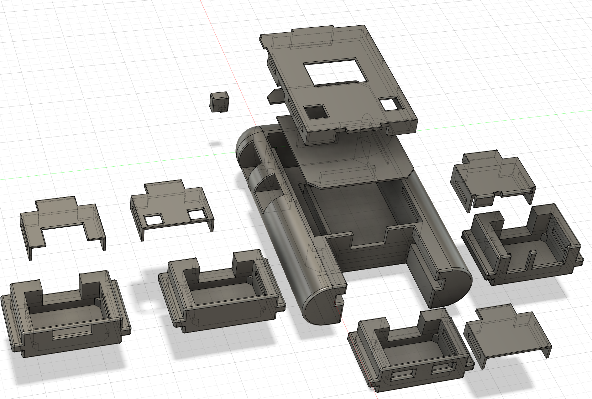
This source code is licensed under MIT. Other Hardware Schematic documents are licensed under CC-BY-SA V4.0.
| Qty | Value | Footprint | References |
|---|---|---|---|
| 10 | 10K | Resistor_SMD:R_0805_2012Metric_Pad1.20x1.40mm_HandSolder | R101, R102, R103, R105, R108, R109, R110, R111, R121, R122 |
| 5 | PINOUT | Connector_PinHeader_2.54mm:PinHeader_2x06_P2.54mm_Vertical | J102, J203, J206, J208, J211 |
| 4 | 0.1uF | Capacitor_SMD:C_0603_1608Metric_Pad1.08x0.95mm_HandSolder | C101, C102, C104, C105 |
| 4 | 330 | Resistor_SMD:R_0805_2012Metric_Pad1.20x1.40mm_HandSolder | R114, R115, R119, R120 |
| 3 | 20K 1% | Resistor_SMD:R_0805_2012Metric_Pad1.20x1.40mm_HandSolder | R106, R116, R117 |
| 3 | USB_C_Receptacle_USB2.0_5077CR | tbctl:USB_C_5077CR-16-SMC2-BK-TR | J101, J201, J202 |
| 2 | 10uF | Capacitor_SMD:C_0805_2012Metric_Pad1.18x1.45mm_HandSolder | C103, C106 |
| 2 | 1uF | Capacitor_SMD:C_0805_2012Metric | C107, C109 |
| 2 | 5.1K | Resistor_SMD:R_0603_1608Metric | R123, R124 |
| 2 | LED RED | LED_SMD:LED_0603_1608Metric_Pad1.05x0.95mm_HandSolder | D101, D102 |
| 2 | SW_Push_LED | tbctl:LS601-CU_CAP | SW103, SW104 |
| 2 | TS-06104 | tbctl:TS-06104 | SW101, SW102 |
| 1 | 100K | Resistor_SMD:R_0805_2012Metric_Pad1.20x1.40mm_HandSolder | R118 |
| 1 | 10m | tbctl:R_10mOHM | R104 |
| 1 | 12K 1% | Resistor_SMD:R_0805_2012Metric_Pad1.20x1.40mm_HandSolder | R107 |
| 1 | 1K | Resistor_SMD:R_0805_2012Metric_Pad1.20x1.40mm_HandSolder | R113 |
| 1 | 2K | Resistor_SMD:R_0805_2012Metric_Pad1.20x1.40mm_HandSolder | R112 |
| 1 | 4.7uF | Capacitor_SMD:C_0805_2012Metric_Pad1.18x1.45mm_HandSolder | C108 |
| 1 | BATTERY IN JST_PH | Connector_JST:JST_PH_B2B-PH-K_1x02_P2.00mm_Vertical | J210 |
| 1 | BATTERY OUT JST_PH | Connector_JST:JST_PH_B2B-PH-K_1x02_P2.00mm_Vertical | J209 |
| 1 | BK2125HS601-T | Inductor_SMD:L_0805_2012Metric | FB101 |
| 1 | ESP32-C3-WROOM-02-N4 | Library:IC18_ESP32-C3-WROOM-02-N4_EXP | U101 |
| 1 | INA228 | Package_SO:VSSOP-10_3x3mm_P0.5mm | U102 |
| 1 | IRF7606PBF | Package_SO:MSOP-8_3x3mm_P0.65mm | Q101 |
| 1 | LED GREEN | LED_SMD:LED_0603_1608Metric_Pad1.05x0.95mm_HandSolder | D103 |
| 1 | LiPo BATTERY | Connector_JST:JST_PH_B2B-PH-K_1x02_P2.00mm_Vertical | J104 |
| 1 | MCP73831-2-OT | Package_TO_SOT_SMD:SOT-23-5 | U104 |
| 1 | NSR0340HT1G | Diode_SMD:D_SOD-323_HandSoldering | D104 |
| 1 | SLIDE_SW | tbctl:SLIDE_SW_IS1235-G | SW105 |
| 1 | SPX3819M5-L | Package_TO_SOT_SMD:SOT-23-5 | U103 |
| 1 | SSD1331_DISPLAY | tbctl:OLED SSD1331 SPI DISPLAY | U105 |
| 1 | Screw_Terminal_01x03 | tbctl:TB112-2-2-3-E-1 Terminal Block | J207 |
| 1 | SolderJumper_2_Open | Jumper:SolderJumper-2_P1.3mm_Open_RoundedPad1.0x1.5mm | JP101 |
| 1 | USB_A | tbctl:USB_A_5075AR-04 | J205 |
| 1 | USB_B_Mini | tbctl:usb mini B connector c2235 dim 2 | J204 |
It measures 91.7 × 70 mm and has 2 copper layers, 1.6 mm thick.
64 parts, built around the ESP32-C3-WROOM-02-N4, SPX3819M5-L, BK2125HS601-T and NSR0340HT1G-HXY. The full list of its parts is on this page, with links to each part's symbol and footprint where PCBKit's library has them.
From the hnz1102/current-logger repository on GitHub, at the commit this page was made from: the board is hardware/currentlogger.kicad_pcb and its schematic hardware/adopter.kicad_sch. PCBKit opens the board in the browser, with nothing to install.
Its repository states no licence, so its author keeps all rights: ask hnz1102 before reusing the design.
hnz1102/temp-logger
Logging Thermocouple Temperature and Send Data to InfluxDB system.

hnz1102/mini-current-meter
Mini Current Meter using INA228A ultra-precise digital power monitor


hnz1102/sdcdmux-emmc
SD CARD and eMMC Device Multiplexer with Infrared Remote Controller


hnz1102/shared-usb-memory
USB Memory with One-touch Switching Between Two Device Connections

Luos-io/luos_engine
Open-source and real-time orchestrator for cyber-physical-systems, to easily design, test and deploy embedded applications and digital twins.

apoluekt/OpenRPNCalc
Open-source and open-hardware scientific RPN calculator