2 layers46 × 54 mm
Mini power
hnz1102/mini-power
Mini-Power is a small, portable DC power supply unit designed to provide a convenient and reliable source of adjustable voltage for your electronic devices and breadboard experiments.
52 parts3

 hnz1102/dcpower1
DC Power Unit for Breadboard based on ESP32-S3 microcontroller and AP33772S USB Power Delivery (PD) Sink Controller.
Dcpower is an open-source printed circuit board by hnz1102, from the hnz1102/dcpower repository on GitHub. It is a 2-layer board of 122.2 × 122.8 mm with 115 parts on 99 nets, routed with 855 tracks and 207 vias.
It is built around the ESP32-S3-WROOM-1-N16R8, TSB611ILT and AP33772SDKZ-13-FA01, with the PCA9306D, 0.1UF 50V 5*11 and SK36A-LTP among its other parts. Its parts include 37 resistors, 30 capacitors, 11 ICs, 11 connectors and 5 transistors. It belongs with the power boards and the ESP32 boards of this library.


DC Power Unit for Breadboard
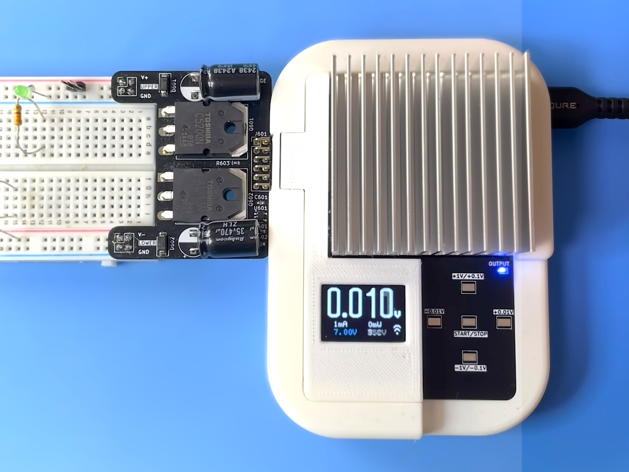
This is a DC Power Unit for Breadboard based on ESP32-S3 microcontroller and AP33772S USB Power Delivery (PD) Sink Controller. It can supply power to the breadboard from USB Power Delivery (PD) Charger with support for both Standard Power Range (SPR) and Extended Power Range (EPR) modes. The output voltage can be controlled from 0v to 20V in SPR mode and up to 28V(*1) in EPR mode with step of 10mV.
There are 2 types of adopters for the output terminal: Single positive power output terminal and dual positive/negative output terminal. It is easy to connect to the breadboard with standard 2.54mm pitch pin header. If you select the dual positive/negative output terminal adopter, the output voltage can be halved by positive and negative voltage. E.g. If you set the output voltage to 20V, you can get +10V and -10V from the positive and negative output terminal.
*1: Maximum voltage is limited to 28V by AP33772S hardware specifications. Some PD chargers may not support EPR mode or only support up to 16V/5A. Please check your PD charger specifications.
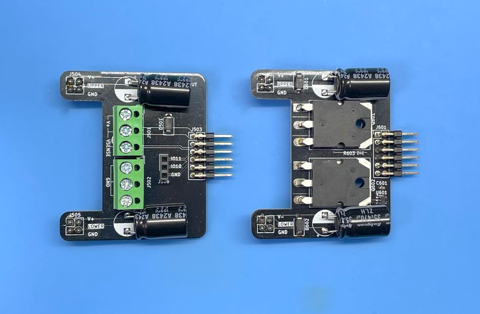
The left image shows the single positive output terminal adopter, and the right image shows the dual positive/negative output terminal adopter.
Note: If you use 21V or higher voltage, input voltage is 28v or higher, and differential voltage is over 3V and output current is over 3A, the MOSFET device is in the high consumption state and the unit temperature may rise over 80 degrees Celsius. Please be careful about the temperature. You can set the maximum temperature in the configuration file. The default value is 80 degrees Celsius. If the temperature exceeds the limit, the output will be disabled automatically. I recommend using less than 0.7A current at 21V or higher voltage. Otherwise, if you set the output voltage to 27V or higher, the temperature rise is not a problem.
Note: This unit uses a micro controller and a USB PD controller. These controllers need the power to operate. Therefore, if you use a over current, the power source may be shut down by the over current protection of the PD charger. In this case, This unit cannot operate and will be turned off. Please use the current within the specification of your PD charger.
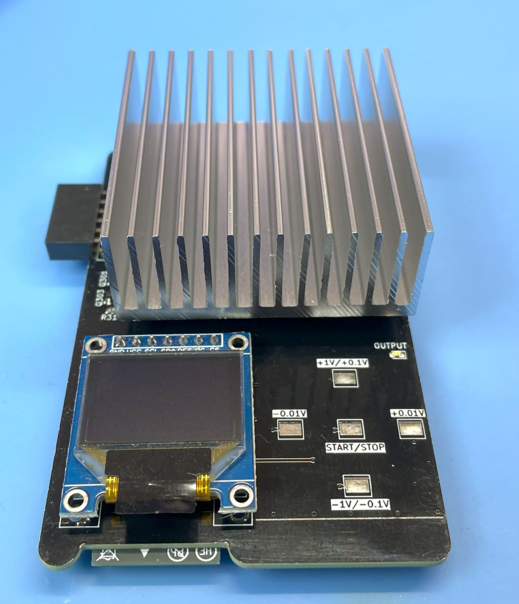
The firmware is written in Rust using the ESP-IDF framework and consists of several modules:
main.rs: Main application logic and system initializationusbpd.rs: AP33772S USB-PD driver interface using the ap33772s-driver cratedisplayctl.rs: OLED display control and user interfacecurrentlogs.rs: Current and voltage measurement using INA228touchpad.rs: Touch sensor interface and user input handlingpidcont.rs: PID controller for voltage regulationwifi.rs: WiFi connectivity and network managementtransfer.rs: Data transmission to InfluxDB serversyslogger.rs: System logging functionalityap33772s-driver crate is used for USB-PD communication with the AP33772S controller. Please see the ap33772s-driver for more details.
If the output is disabled due to over current, over power, or over temperature, you can clear the error message by pressing the center touch position once.
These protections are implemented by the AP33772S.
The project uses the custom ap33772s-driver crate for USB-PD communication:
[dependencies]
ap33772s-driver = { version = "0.1.4", features = ["std"] }
Other key dependencies include:
esp-idf-hal v0.45.2: ESP32 hardware abstractionembedded-hal v1.0.0: Platform-agnostic hardware interfacesssd1331 v0.3.0: OLED display driverembedded-graphics v0.7: Graphics primitives for displaychrono v0.4.38: Date and time handlingtoml-cfg v0.1.3: Configuration file parsingUsing Ubuntu 22.04.3 LTS and ESP-IDF V5.4.2
Ensure that your system meets the following requirements before proceeding with the installation:
Update your system and install the necessary packages using:
sudo apt update && sudo apt -y install git python3 python3-pip gcc build-essential curl pkg-config libudev-dev libtinfo5 clang libclang-dev llvm-dev udev libssl-dev python3.10-venvInstall Rust programming language and Cargo package manager:
curl --proto '=https' --tlsv1.2 -sSf https://sh.rustup.rs | shAfter installation, activate Rust by sourcing the environment:
. "$HOME/.cargo/env"Install the following Rust tools:
Use the following commands:
cargo install ldproxy
cargo install espup
cargo install cargo-espflash
At this time (2025-07-25), espup cannot be compiled. If you get an error, please use the following command to install the toolchain.
cargo install cargo-binstall
cargo binstall espupRun the following command to install and update the Espressif Rust ecosystem:
espup install
espup update
Set up environment variables:
. ./export-esp.shConfigure udev rules for device permissions:
sudo sh -c 'echo "SUBSYSTEMS==\"usb\", ATTRS{idVendor}==\"303a\", ATTRS{idProduct}==\"1001\", MODE=\"0666\"" > /etc/udev/rules.d/99-esp32.rules'
sudo udevadm control --reload-rules
sudo udevadm triggerClone the DC Power Unit repository:
git clone https://github.com/hnz1102/dcpower.git
cd dcpower/codeChange the following configuration file: cfg.toml
You have to set the following parameters: WiFi SSID, Password, InfluxDB Server IP Address, InfluxDB API Key, and InfluxDB API with your ORG.
You can get the API Key from the InfluxDB Web Console. Please see the 'How to Install the InfluxDB and Configure the Dashboard' section No.3.
[dcpowerunit]
wifi_ssid = "<Your AP SSID>"  # Set your AP SSID
wifi_psk = "<Your AP Password>" # Set your AP Password
influxdb_server = "<InfluxDB Server IP Address:Port>" # Set your InfluxDB Server IP Address and Port ex. 192.168.1.100:8086
pid_kp = "0.0000005"
pid_ki = "0.00002"
pid_kd = "0.1"
pwm_offset = "0"
pd_config_offset = "1.5"
shunt_resistance = "0.005"
shunt_temp_coefficient = "50"
max_current_limit = "5.2"
max_power_limit = "100.0"
max_temperature_limit = "75" # Set the maximum temperature limit in degrees Celsius. Default is 75 degrees.
influxdb_api_key = "<InfluxDB API KEY>" # Set your InfluxDB API Key
influxdb_api = "/api/v2/write?org=<ORG>&bucket=LOGGER&precision=ns" # Set your InfluxDB API with your ORG and BUCKET
influxdb_tag = "dcpowerunit"  # Tag for InfluxDB measurements
influxdb_measurement = "dcpowerunit" # Measurement name for InfluxDB
syslog_server = "<Syslog Server IP Address:Port>" # Set your Syslog Server IP Address and Port ex. 192.168.2.140:514
syslog_enable = "false" # Set to "true" to enable syslogBuild the project:
cargo build --releaseConnect the DC Power Unit to your PC using a USB cable. Then, flash the firmware:
cargo espflash flash --release --monitorIf your device is not detected, power on the device and during the boot, press the BOOT button.
Then, run the flash command again.
After flashing the firmware, the console shows the booting messages and system initialization including:
Chip type:         esp32s3 (revision v0.2)
Crystal frequency: 40 MHz
Flash size:        16MB
Features:          WiFi, BLE, Embedded Flash
MAC address:       80:65:99:b8:8e:90
App/part. size:    1,383,760/1,536,000 bytes, 90.09%
[00:00:00] [========================================]      14/14      0x0      Verifying... OK!
[00:00:00] [========================================]       1/1       0x8000   Skipped! (checksum matches)
[00:00:15] [========================================]     864/864     0x10000  Verifying... OK!
[2025-09-15T07:23:38Z INFO ] Flashing has completed!
Commands:
    CTRL+R    Reset chip
    CTRL+C    Exit

ESP-ROM:esp32s3-20210327
Build:Mar 27 2021
rst:0x15 (USB_UART_CHIP_RESET),boot:0x8 (SPI_FAST_FLASH_BOOT)
Saved PC:0x40378d03
0x40378d03 - setup_priv_desc$isra$0
    at ??:??
SPIWP:0xee
mode:DIO, clock div:2
load:0x3fce2810,len:0x1564
load:0x403c8700,len:0x4$ wget https://dl.influxdata.com/influxdb/releases/influxdb2-2.7.0-amd64.deb
$ sudo dpkg -i influxdb2-2.7.0-amd64.deb
$ sudo service influxdb startConnect to the 'http://<influxDB installed PC Address>:8086'Click GET STARTED and set Username, Password, Initial Organization Name, and Initial Bucket Name
| Term | Value |
|---|---|
| Username | Set login username as influxDB administrator web console |
| Password | Set login password as influxDB administrator web console |
| Initial Organization Name | Organization Name ex. ORG |
| Initial Bucket Name | LOGGER |
After set them, click CONTINUE.
You can see the operator API token on the browser. YOU WON'T BE ABLE TO SEE IT AGAIN!
If you want to get new API token, click API Tokens menu form Sources Icon, then click GENERATE API TOKEN and select All access token, click Save.
You can see a new API token and get it.
After copy the token, click CONFIGURE LATER.
Click the Dashboard icon, and select Import Dashboard from the CREATE DASHBOARD menu.
Drop the influxdb/dc_power_station.json file to Drop a file here, then click IMPORT JSON AS DASHBOARD.
You can see the DC POWER STATION pannel on the Dashboards page.
Click this panel, and You can see the dashboard.
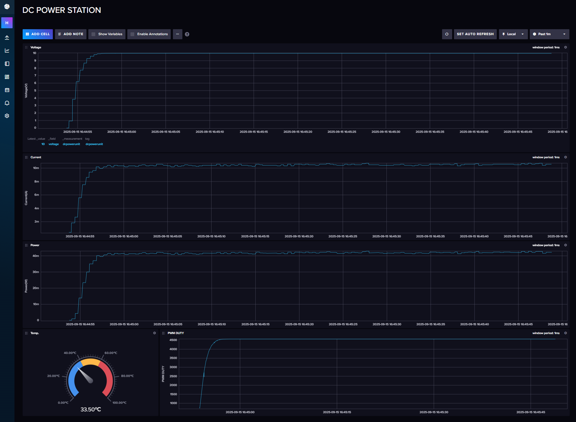
If you want to customize the dashboard design, click configure mark. You can change the graph design.
There is a Schematic data in hardware directory.
This PCB is designed by Kicad.
This source code is licensed under MIT. Other Hardware Schematic documents are licensed under CC-BY-SA V4.0.
| Qty | Value | Footprint | References |
|---|---|---|---|
| 10 | 10K 1% | Resistor_SMD:R_0603_1608Metric | R301, R306, R309, R310, R316, R317, R318, R319, R601, R602 |
| 9 | 0.1uF | Capacitor_SMD:C_0603_1608Metric | C201, C202, C304, C308, C401, C402, C404, C405, C409 |
| 9 | 0.1uF/50V | Capacitor_SMD:C_0603_1608Metric | C303, C305, C306, C307, C310, C314, C406, C408, C601 |
| 7 | 10K | Resistor_SMD:R_0603_1608Metric | R201, R202, R205, R302, R303, R304, R405 |
| 4 | 1K 1% | Resistor_SMD:R_0603_1608Metric | R305, R307, R311, R312 |
| 4 | 470uF | Capacitor_THT:CP_Radial_D8.0mm_P5.00mm | C501, C502, C602, C603 |
| 3 | SK36A-LTP | Diode_SMD:D_SMA | D501, D601, D602 |
| 2 | 10uF/50V | Capacitor_SMD:C_0805_2012Metric | C316, C407 |
| 2 | 1K | Resistor_SMD:R_0603_1608Metric | R314, R411 |
| 2 | 4.7K | Resistor_SMD:R_0603_1608Metric | R412, R413 |
| 2 | 5K1 | Resistor_SMD:R_0603_1608Metric | R409, R410 |
| 2 | 5m | Resistor_SMD:R_2512_6332Metric_Pad1.40x3.35mm_HandSolder | R308, R414 |
| 2 | ADPIN | Connector_PinHeader_2.54mm:PinHeader_2x06_P2.54mm_Vertical | J503, J601 |
| 2 | LOWER OUT | Connector_PinHeader_2.54mm:PinHeader_2x02_P2.54mm_Vertical | J505, J603 |
| 2 | OPA187IDBVR | Package_TO_SOT_SMD:SOT-23-5 | U301, U305 |
| 2 | Screw_Terminal_3P | Library:TB112-2-2-3-E-1 Terminal Block | J501, J502 |
| 2 | TSB611ILT | Package_TO_SOT_SMD:SOT-23-5 | U304, U601 |
| 2 | UPPER OUT | Connector_PinHeader_2.54mm:PinHeader_2x02_P2.54mm_Vertical | J504, J602 |
| 1 | 0.01uF/50V | Capacitor_SMD:C_0603_1608Metric | C312 |
| 1 | 0.47uF/50V | Capacitor_SMD:C_0603_1608Metric | C403 |
| 1 | 100 | Resistor_SMD:R_0603_1608Metric | R417 |
| 1 | 1000pF | Capacitor_SMD:C_0603_1608Metric | C309 |
| 1 | 100K 1% | Resistor_SMD:R_0603_1608Metric | R315 |
| 1 | 10uF | Capacitor_SMD:C_0805_2012Metric | C301 |
| 1 | 150 | Resistor_SMD:R_0603_1608Metric | R203 |
| 1 | 1uF | Capacitor_SMD:C_0805_2012Metric | C410 |
| 1 | 200K | Resistor_SMD:R_0603_1608Metric | R401 |
| 1 | 220 | Resistor_SMD:R_0603_1608Metric | R603 |
| 1 | 2N7002K | Package_TO_SOT_SMD:SOT-23 | Q303 |
| 1 | 2SA1943 | Package_TO_SOT_THT:TO-3P-3_Horizontal_TabDown | Q602 |
| 1 | 2SC3325 | Package_TO_SOT_SMD:SC-59 | Q301 |
| 1 | 2SC5200 | Package_TO_SOT_THT:TO-3P-3_Horizontal_TabDown | Q601 |
| 1 | 3.09K 1% | Resistor_SMD:R_0603_1608Metric | R313 |
| 1 | 3.5x2.6 Tact SW | Library:WS-TASV SMT Tact Switch | SW201 |
| 1 | 4.7K 1% | Resistor_SMD:R_0603_1608Metric | R206 |
| 1 | 47K 1% | Resistor_SMD:R_0603_1608Metric | R204 |
| 1 | 47pF | Capacitor_SMD:C_0603_1608Metric | C311 |
| 1 | AP33772SDKZ-13-FA01 | Library:W-QFN4040-24_Type_A1_DIO | U403 |
| 1 | BOOT | TestPoint:TestPoint_Pad_D1.0mm | TP202 |
| 1 | ESP32-S3-WROOM-1-N16R8 | Library:ESP32-S3-WROOM-1_EXP | U201 |
| 1 | GND | TestPoint:TestPoint_Pad_D1.0mm | TP309 |
| 1 | GPIO | Connector_PinHeader_2.54mm:PinHeader_1x03_P2.54mm_Vertical | J506 |
| 1 | INA228 | Package_SO:VSSOP-10_3x3mm_P0.5mm | U302 |
| 1 | IRFP9140NPBF | Package_TO_SOT_THT:TO-247-3_Horizontal_TabUp | Q302 |
| 1 | Jumper | Jumper:SolderJumper-2_P1.3mm_Bridged_RoundedPad1.0x1.5mm | JP301 |
| 1 | LED BLUE | LED_SMD:LED_0603_1608Metric | D402 |
| 1 | LM35-NEB | Package_TO_SOT_THT:TO-220-3_Horizontal_TabDown | U303 |
| 1 | MH2029-601Y | Inductor_SMD:L_0805_2012Metric | FB401 |
| 1 | OP-VCC | TestPoint:TestPoint_Pad_D1.0mm | TP304 |
| 1 | PCA9306D | Package_SO:SSOP-8_2.95x2.8mm_P0.65mm | U401 |
| 1 | PINOUT | Connector_PinHeader_2.54mm:PinHeader_2x06_P2.54mm_Vertical | J305 |
| 1 | PWM | TestPoint:TestPoint_Pad_D1.0mm | TP301 |
| 1 | SET-Vr | TestPoint:TestPoint_Pad_D1.0mm | TP302 |
| 1 | SSD1331_DISPLAY | Library:OLED SSD1331 SPI DISPLAY | U202 |
| 1 | TOUCH1 | Library:TestPoint_Pad_3.2x1.6mm | TP-PAD201 |
| 1 | TOUCH2 | Library:TestPoint_Pad_3.2x1.6mm | TP-PAD202 |
| 1 | TOUCH3 | Library:TestPoint_Pad_3.2x1.6mm | TP-PAD203 |
| 1 | TOUCH4 | Library:TestPoint_Pad_3.2x1.6mm | TP-PAD204 |
| 1 | TOUCH5 | Library:TestPoint_Pad_3.2x1.6mm | TP-PAD205 |
| 1 | TPGND | Library:TestPoint_Pad_3.2x1.6mm | TP-PAD301 |
| 1 | UA78M33 | Package_TO_SOT_THT:TO-220-3_Horizontal_TabUp | U402 |
| 1 | USB4105-GF-A | Library:USB_C_5077CR-16-SMC2-BK-TR | J401 |
| 1 | Vb | TestPoint:TestPoint_Pad_D1.0mm | TP306 |
| 1 | Vfb | TestPoint:TestPoint_Pad_D1.0mm | TP303 |
| 1 | Vref | TestPoint:TestPoint_Pad_D1.0mm | TP310 |
It measures 122.2 × 122.8 mm and has 2 copper layers, 1.6 mm thick.
115 parts, built around the ESP32-S3-WROOM-1-N16R8, TSB611ILT, AP33772SDKZ-13-FA01 and PCA9306D. The full list of its parts is on this page, with links to each part's symbol and footprint where PCBKit's library has them.
From the hnz1102/dcpower repository on GitHub, at the commit this page was made from: the board is hardware/dcpower.kicad_pcb and its schematic hardware/adoptpr-r2.kicad_sch. PCBKit opens the board in the browser, with nothing to install.
Its repository states no licence, so its author keeps all rights: ask hnz1102 before reusing the design.
hnz1102/mini-power
Mini-Power is a small, portable DC power supply unit designed to provide a convenient and reliable source of adjustable voltage for your electronic devices and breadboard experiments.


picli3/etapa-potencia-500w
Barra de potencia de audio con múltiples transistores en paralelo, pensada para entregar alta corriente y robustez térmica en amplificadores de gran potencia.

X-ANONYMOUS-POWER-AMPLIFIER/X-B120W-4-LITE
SIMPLE MAIN-CIRCUIT MODULE OF 120 WATTS CLASS-B AUDIO POWER AMPLIFIER MAIN-CIRCUIT FOR 4-OHMS OUTPUT LOAD

X-ANONYMOUS-POWER-AMPLIFIER/X-B350W-4-LITE
SIMPLIFIED MAIN-CIRCUIT MODULE OF 350 WATTS CLASS-B AUDIO POWER AMPLIFIER MAIN-CIRCUIT FOR 4-OHMS OUTPUT LOAD


motor-and-motion-control-lab/mmlab-12PhaseDrive-388Slave
PCB Electronics for Humanoid Robots and Bearingless Motor Systems
