2 layers85 × 90 mm
Schematics
LyubomirNachev/Diplomna
Проектиране на сензорна IoT мрежа, използваща протокола Thread.
20 parts2

 K0nradG/self-balancing-robot4
Self-balancing robot powered by nRF52840 and Zephyr RTOS, with BLE control, OTA updates, and a Raspberry Pi camera interface designed for future autonomous navigation.
Self balancing robot is an open-source printed circuit board by K0nradG, from the K0nradG/self-balancing-robot repository on GitHub, published under the Apache-2.0 licence. It is a 2-layer board of 139.7 × 114.3 mm with 36 parts on 30 nets, routed with 205 tracks and 41 vias.
It is built around the LM1117DT-3.3, NRF52840-DONGLE and 1101M2S3CQE2. Its parts include 5 resistors, 3 ICs, 3 connectors, 2 capacitors and 1 switch. It belongs with the robots and motor control and radio and wireless boards and the nRF52 and nRF5x boards of this library.


This project is licensed under the CERN Open Hardware Licence Version 2 - Permissive (CERN-OHL-P).
The license covers all design files in this directory, including:
robot-case directory).Copyright © 2026 Dymczyk Filip and Konrad Grucel
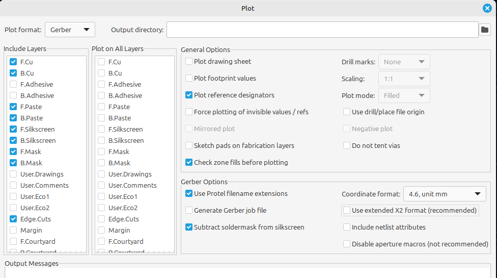
To generate new Gerber files after making changes to the schematic, follow this guide.
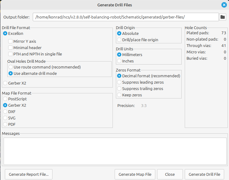
For drill files .drl, follow these steps:
Adding Custom Symbols, Footprints, and 3D Models
You can find various custom symbols, footprints, and 3D models online. Recommended sources:
All external symbols, footprints, and 3D models used in this project are located in the external-3d-models and external-symbols-footprints directories. The sources for these components are documented in utils/external-parts-Kicad.txt.
Example files from [SnapEDA](https://www.snapeda.com/parts/GY-521/GODREAM FORDREAM CO., LIMITED/view-part):
.kicad_sym.kicad_mod.kicad_sym file.Open the KiCad schematic editor.
click the following icon

Click Preferences → Manage footprints Libraries, and provide an path to the .kicad_mod file
next you have to click Preferences button button and then Manage footprints liblaries
then you have to click directory(folder) icon and provide a path to your .kicad_mod file.
**note: ** the kicad_mod and kicad_sym files can be in the same directory. if you download footprint and symbol package.
.wrl or .step file.| Qty | Value | Footprint | References |
|---|---|---|---|
| 3 | 100k | Resistor_THT:R_Axial_DIN0207_L6.3mm_D2.5mm_P5.08mm_Vertical | R1, R2, R3 |
| 2 | 100uF | Capacitor_THT:C_Disc_D7.5mm_W4.4mm_P5.00mm | C1, C3 |
| 2 | 10kR | Resistor_THT:R_Axial_DIN0207_L6.3mm_D2.5mm_P5.08mm_Vertical | R4, R5 |
| 2 | 282837-2 | 282837-2:TE_282837-2 | P1, P2 |
| 1 | 1101M2S3CQE2 | 1101M2S3CQE2:SW_1101M2S3CQE2 | S1 |
| 1 | GY-521 | GY-521:GY-521 | ACC1 |
| 1 | LM1117DT-3.3 | Package_TO_SOT_SMD:TO-252-3_TabPin2 | U3 |
| 1 | NRF52840-DONGLE | NRF52840-DONGLE:MODULE_NRF52840-DONGLE | U1 |
| 1 | POLOLU-713 | POLOLU-713:SHIELD_POLOLU-713 | TB1 |
| 1 | S2B-PH-K-S_LF__SN_ | S2B-PH-K-S_LF__SN_:JST_S2B-PH-K-S_LF__SN_ | J1 |
| 1 | YAAJ_DCDC_StepDown_LM2596 | lm256:YAAJ_DCDC_StepDown_LM2596 | U4 |
The 16 most common of 36 parts.
LyubomirNachev/Diplomna
Проектиране на сензорна IoT мрежа, използваща протокола Thread.

mrozsebastian/TSDZ2-NRF-module-board
Simple, low component count, inspired by @stsdc


Dawn-Of-Justice/project-revgen
A voice-controlled system designed to help elderly people interact with electronic devices through natural language commands in their native language.


ezer-soltani/HellKitty-Autonomous-Robot
Professional firmware and hardware design for an autonomous mobile robot using STM32G431 and FreeRTOS. Features Lidar perception, ToF safety algorithms, and PID motor control.


mahdi-kh1265/780nm-ecdl-electronics
Control, interface, piezo-actuation, and power electronics for POSM's 780 nm Littrow external-cavity diode laser.
It measures 139.7 × 114.3 mm and has 2 copper layers, 1.6 mm thick.
36 parts, built around the LM1117DT-3.3, NRF52840-DONGLE and 1101M2S3CQE2. The full list of its parts is on this page, with links to each part's symbol and footprint where PCBKit's library has them.
From the K0nradG/self-balancing-robot repository on GitHub, at the commit this page was made from: the board is Schematic/Schematic.kicad_pcb and its schematic Schematic/Schematic.kicad_sch. PCBKit opens the board in the browser, with nothing to install.
Its repository publishes it under the Apache-2.0 licence: you may reuse it on that licence's terms (keep the author's notice, and for a copyleft licence share your changes alike).