Skip to the content
PCBKitNew board
4 layers100 × 86.3 mmArchives, the printed circuit board in 3D

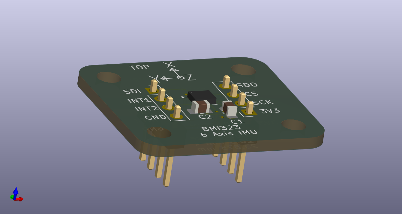
This directory contains the electrical schematic for a breakout board for the Bosch BMI323 6-axis IMU. This IMU provides a 16 bit digital triaxial accelerometer, a 16 bit digital triaxial gyroscope, and a 16 bit digital…

Size
100 × 86.3 mm
Copper layers
4
Thickness
1.77 mm
Parts
138
Nets
200
Pads
653
Tracks, vias
1,509, 231
Pours
3
Routed
Yes
KiCad
KiCad 7 (file 20221018)
Created
8 Nov 2023
Updated
22 Oct 2026

Overview

Archives is an open-source printed circuit board by satomm1, from the satomm1/Robot repository on GitHub, published under the MIT licence. It is a 4-layer board of 100 × 86.3 mm with 138 parts on 200 nets, routed with 1,509 tracks and 231 vias.

It is built around the PIC32MZ2048EFH144-I/PL, DRV8842PWPR and MEM2061-01-188-00-A, with the GSF7002DW, AP2114HA-3.3TRG1 and ICM-42688-P among its other parts. Its parts include 40 resistors, 35 capacitors, 22 connectors, 14 ICs and 10 diodes. It belongs with the sensors and measurement boards and the PIC boards of this library.

Main components

7

README

Electrical/IMU_Breakout/README.md

6-axis IMU

This directory contains the electrical schematic for a breakout board for the Bosch BMI323 6-axis IMU. This IMU provides a 16 bit digital triaxial accelerometer, a 16 bit digital triaxial gyroscope, and a 16 bit digital temperature sensor.

This breakout board is designed so that the IMU can be placed anywhere that is convenient.

Soldering the IMU

This IMU is in a QFN package, which means the device should be reflow soldered. Alternatively, you can carefully apply solder to the PCB pads, put the IMU on top, and use a heat gun to solder the IMU.

Pin directions

The header pins should be soldered on the bottom of the PCB:

IMU Breakout Board

Installing the IMU

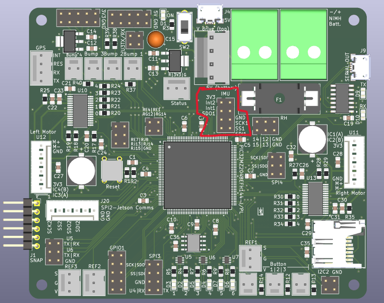
The assembly is meant to be installed on the robot with the IMU facing upwards. The positive X/Y/Z axes are designated on the board. The IMU should be connected via wire to the designated header on the main control board:

IMU Breakout PinMain Control Board Connection
3V33.3V
GNDGND
SCKSCK
CSCS
SDOSDI
SDISDO
INT1INT1 (Currently Unused)
INT2INT2 (Currently Unused)

The IMU connection on the main control board is indicated below:

Main Board with IMU Pins Highlighted

Parts

138
QtyValueFootprintReferences
220.1 uFCapacitor_SMD:C_0805_2012Metric_Pad1.18x1.45mm_HandSolderC1, C2, C3, C10, C17, C19, C22, C23, C24, C27, C28, C30, C31, C32, C35, C36 +6
11130RResistor_SMD:R_0805_2012Metric_Pad1.20x1.40mm_HandSolderR3, R4, R5, R6, R7, R8, R9, R10, R11, R15, R16
100RResistor_SMD:R_0805_2012Metric_Pad1.20x1.40mm_HandSolderR20, R21, R22, R23, R24, R30, R31, R32, R33, R34
9LEDLED_SMD:LED_0805_2012Metric_Pad1.15x1.40mm_HandSolderD1, D2, D3, D4, D5, D6, D7, D9, D10
81kResistor_SMD:R_0805_2012Metric_Pad1.20x1.40mm_HandSolderR2, R12, R13, R14, R37, R38, R39, R40
5Conn_02x03_Odd_EvenConnector_PinHeader_2.54mm:PinHeader_2x03_P2.54mm_VerticalJ16, J19, J20, J21, J23
44.7 uFCapacitor_SMD:C_0805_2012Metric_Pad1.18x1.45mm_HandSolderC11, C12, C13, C14
4GSF7002DWPackage_TO_SOT_SMD:SOT-363_SC-70-6U5, U6, U7, U8
4MountingHoleMountingHole:MountingHole_3.2mm_M3H1, H2, H3, H4
4SW_SPSTRobotLibrary:CONN_22232021_MOLSW7, SW8, SW9, SW10
30.01 uFCapacitor_SMD:C_0805_2012Metric_Pad1.18x1.45mm_HandSolderC16, C21, C29
310kResistor_SMD:R_0805_2012Metric_Pad1.20x1.40mm_HandSolderR1, R17, R27
3Conn_02x02_Odd_EvenConnector_PinHeader_2.54mm:PinHeader_2x02_P2.54mm_VerticalJ18, J22, J25
3Refl_PCB_ConnectRobotLibrary:CONN3_22232031_MOLJ13, J14, J15
3User_ButtonRobotLibrary:CONN_22232021_MOLSW4, SW5, SW6
20.25RResistor_SMD:R_0805_2012Metric_Pad1.20x1.40mm_HandSolderR26, R36
20.47 uFCapacitor_SMD:C_0805_2012Metric_Pad1.18x1.45mm_HandSolderC20, C26
2100 uFRobotLibrary:PCAP_8x10-ELECT_NCA-MC25, C33
216kResistor_SMD:R_0805_2012Metric_Pad1.20x1.40mm_HandSolderR18, R28
21MResistor_SMD:R_0805_2012Metric_Pad1.20x1.40mm_HandSolderR25, R35
251kResistor_SMD:R_0805_2012Metric_Pad1.20x1.40mm_HandSolderR19, R29
2AP2114HA-3.3TRG1RobotLibrary:SOT-223_DIO-MU2, U3
2Battery1RobotLibrary:CONN_1017514J5, J6
2DRV8842PWPRRobotLibrary:PWP0028C_MU10, U13
2Motor_DCRobotLibrary:CONN_1890963_PXCM1, M2
2Quad_EncoderRobotLibrary:CONN_22-23-2041_MOLU11, U12
2USB_B_MicroRobotLibrary:AMPHENOL_10118193-0001LFJ4, J9
110 uFCapacitor_THT:CP_Radial_Tantal_D5.0mm_P2.50mmC15
12.2 uFCapacitor_SMD:C_0805_2012Metric_Pad1.18x1.45mm_HandSolderC18
13.3V SupplyConnector_PinHeader_2.54mm:PinHeader_2x05_P2.54mm_VerticalJ2
15A FuseRobotLibrary:FUSE_4628F1
15V BypassRobotLibrary:SPDT_OS102011_CNKSW2
15V SupplyConnector_PinHeader_2.54mm:PinHeader_2x05_P2.54mm_VerticalJ3
1All Power SwitchRobotLibrary:26-60-4040_MOLSW3
1Conn_01x04RobotLibrary:CONN_22-23-2041_MOLJ24
1Conn_02x04_Odd_EvenConnector_PinHeader_2.54mm:PinHeader_2x04_P2.54mm_VerticalJ8
1GPIO1Connector_PinHeader_2.54mm:PinHeader_2x05_P2.54mm_VerticalJ7
1ICM-42688-PRobotLibrary:LGA14_2P5X3X0P91_TDK-MU4
1M95M01-DFMN6TPRobotLibrary:SO8N_4X5X1P27_STM-MU15
1MCP2221A-I_SLRobotLibrary:SOIC127P600X175-14NU9
1MEM2061-01-188-00-ARobotLibrary:MEM2061-01-188-00-A_GCTJ17
1PIC32MZ2048EFH144-I/PLRobotLibrary:LQFP144_PL_MCH-MU1
1ResetRobotLibrary:SW_B3F-1000_OMRSW1
1SNAP ProgramConnector_PinSocket_2.54mm:PinSocket_1x06_P2.54mm_HorizontalJ1
1Status_LEDRobotLibrary:CONN3_22232031_MOLD8

Questions

How big is the Archives PCB?

It measures 100 × 86.3 mm and has 4 copper layers, 1.77 mm thick.

What parts does the Archives use?

138 parts, built around the PIC32MZ2048EFH144-I/PL, DRV8842PWPR, MEM2061-01-188-00-A and GSF7002DW. The full list of its parts is on this page, with links to each part's symbol and footprint where PCBKit's library has them.

Where can I download the Archives KiCad files?

From the satomm1/Robot repository on GitHub, at the commit this page was made from: the board is Electrical/Archives/V0.1/MainBoard/MainBoard.kicad_pcb and its schematic Electrical/Archives/V0.1/MainBoard/Buttons.kicad_sch. PCBKit opens the board in the browser, with nothing to install.

Can I use the Archives design in my own project?

Its repository publishes it under the MIT licence: you may reuse it on that licence's terms (keep the author's notice, and for a copyleft licence share your changes alike).

More from satomm1/Robot

8
  • 4 layers100 × 86.3 mmArchives, the printed circuit board in 3D

    Archives

    satomm1/Robot

    This directory contains the electrical schematic for a breakout board for the Bosch BMI323 6-axis IMU. This IMU provides a 16 bit digital triaxial accelerometer, a 16 bit digital triaxial gyroscope, and a 16 bit digital…

    137 partsMIT
  • 2 layers41.5 × 31.6 mmMCU DSP, the printed circuit board in 3D

    MCU DSP

    satomm1/Robot

    This directory contains the electrical schematic for a breakout board for the Bosch BMI323 6-axis IMU. This IMU provides a 16 bit digital triaxial accelerometer, a 16 bit digital triaxial gyroscope, and a 16 bit digital…

    23 partsMIT
  • 2 layers27.3 × 29.4 mmCO Sensor, the printed circuit board in 3D

    CO Sensor

    satomm1/Robot

    This directory contains the electrical schematic for a breakout board for the Bosch BMI323 6-axis IMU. This IMU provides a 16 bit digital triaxial accelerometer, a 16 bit digital triaxial gyroscope, and a 16 bit digital…

    16 partsMIT
  • 2 layers19.3 × 14.2 mmEnvironmentSensor2, the printed circuit board in 3D

    EnvironmentSensor2

    satomm1/Robot

    This directory contains the electrical schematic for a breakout board for the Bosch BMI323 6-axis IMU. This IMU provides a 16 bit digital triaxial accelerometer, a 16 bit digital triaxial gyroscope, and a 16 bit digital…

    11 partsMIT
  • 2 layers26.5 × 6.5 mmReflectiveSensor, the printed circuit board in 3D

    ReflectiveSensor

    satomm1/Robot

    This directory contains the electrical schematic for a breakout board for the Bosch BMI323 6-axis IMU. This IMU provides a 16 bit digital triaxial accelerometer, a 16 bit digital triaxial gyroscope, and a 16 bit digital…

    7 partsMIT
  • 2 layers26.5 × 23.9 mmIMU Breakout, the printed circuit board in 3D

    IMU Breakout

    satomm1/Robot

    This directory contains the electrical schematic for a breakout board for the Bosch BMI323 6-axis IMU. This IMU provides a 16 bit digital triaxial accelerometer, a 16 bit digital triaxial gyroscope, and a 16 bit digital…

    7 partsMIT
  • 2 layers18.3 × 16.7 mmEnvironmentSensor, the printed circuit board in 3D

    EnvironmentSensor

    satomm1/Robot

    This directory contains the electrical schematic for a breakout board for the Bosch BMI323 6-axis IMU. This IMU provides a 16 bit digital triaxial accelerometer, a 16 bit digital triaxial gyroscope, and a 16 bit digital…

    6 partsMIT
  • 2 layers20.8 × 15 mmMicrophone, the printed circuit board in 3D

    Microphone

    satomm1/Robot

    This directory contains the electrical schematic for a breakout board for the Bosch BMI323 6-axis IMU. This IMU provides a 16 bit digital triaxial accelerometer, a 16 bit digital triaxial gyroscope, and a 16 bit digital…

    5 partsMIT

Similar boards

  • 4 layers152.4 × 152.4 mmCSTAR, the printed circuit board in 3D

    CSTAR

    GenerateNU/Concrete

    192 parts1
  • 10 layers30.6 × 65 mmEffectiveRangeHat simple, the printed circuit board in 3D

    EffectiveRangeHat simple

    EffectiveRange/pcb-mrhat

    PCB project for MrHAT RPi extension hat project

    117 parts2
  • 4 layers65 × 30 mmEffecitveRangeMic2, the printed circuit board in 3D

    EffecitveRangeMic2

    EffectiveRange/pcb-micdevice2

    PCB project for stereo mems microphone with RGB led and MCU

    42 parts
  • 2 layers44.5 × 50.8 mmDropkick, the printed circuit board in 3D

    Dropkick

    rrainey/dropkick

    A data logger designed for skydivers

    50 parts7
  • 8 layers153.7 × 88.9 mmLink, the printed circuit board in 3D

    Link

    oro-os/link

    The Oro OS CI/CD pipeline including PCBs, CAD files, firmware and server infrastructure

    381 parts14MIT
  • 4 layers31 × 45 mmTrick tracker, the printed circuit board in 3D

    Trick tracker

    HomeSmartMesh/bike_trick_tracker

    Tracking sensors for bike movements like height from pressure 9 axis and ToF with record and telemetry

    61 parts2MIT
  • 4 layers58.4 × 54 mmTempo bt, the printed circuit board in 3D

    Tempo bt

    rrainey/tempo-bt

    A Bluetooth LE version of the Tempo Skydiving data logger

    69 parts1GPL-3.0
  • 4 layers243.2 × 134 mmSimulation Main Board, the printed circuit board in 3D

    Simulation Main Board

    Swimnato/Simulation-Main-Board

    A universal Main board developed for the Christa McAuliffe Space center

    564 parts1MIT