Skip to the content
PCBKitNew board
2 layers27.3 × 29.4 mmCO Sensor, the printed circuit board in 3D

CO Sensor

satomm1/Robot

This directory contains the electrical schematic for a breakout board for the Bosch BMI323 6-axis IMU. This IMU provides a 16 bit digital triaxial accelerometer, a 16 bit digital triaxial gyroscope, and a 16 bit digital…

Size
27.3 × 29.4 mm
Copper layers
2
Thickness
1.65 mm
Parts
16
Nets
8
Pads
38
Tracks, vias
125, 11
Pours
1
Routed
Yes
KiCad
KiCad 9.0 (file 20241229)
Created
8 Nov 2023
Updated
22 Oct 2026

Overview

CO Sensor is an open-source printed circuit board by satomm1, from the satomm1/Robot repository on GitHub, published under the MIT licence. It is a 2-layer board of 27.3 × 29.4 mm with 16 parts on 8 nets, routed with 125 tracks and 11 vias.

It is built around the TP5552-VR. Its parts include 5 resistors, 4 capacitors, 3 ICs and 1 connector. It belongs with the sensors and measurement boards of this library.

Main components

1

README

Electrical/IMU_Breakout/README.md

6-axis IMU

This directory contains the electrical schematic for a breakout board for the Bosch BMI323 6-axis IMU. This IMU provides a 16 bit digital triaxial accelerometer, a 16 bit digital triaxial gyroscope, and a 16 bit digital temperature sensor.

This breakout board is designed so that the IMU can be placed anywhere that is convenient.

Soldering the IMU

This IMU is in a QFN package, which means the device should be reflow soldered. Alternatively, you can carefully apply solder to the PCB pads, put the IMU on top, and use a heat gun to solder the IMU.

Pin directions

The header pins should be soldered on the bottom of the PCB:
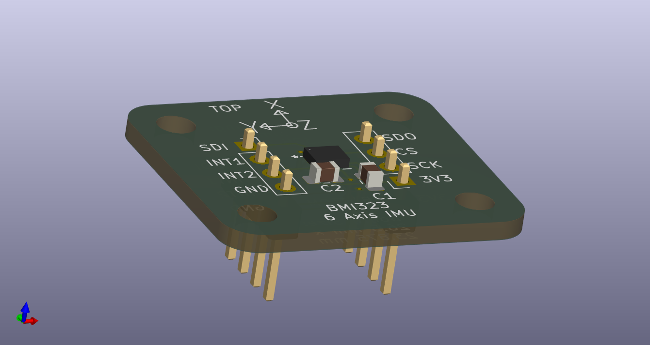
IMU Breakout Board

Installing the IMU

The assembly is meant to be installed on the robot with the IMU facing upwards. The positive X/Y/Z axes are designated on the board. The IMU should be connected via wire to the designated header on the main control board:

IMU Breakout PinMain Control Board Connection
3V33.3V
GNDGND
SCKSCK
CSCS
SDOSDI
SDISDO
INT1INT1 (Currently Unused)
INT2INT2 (Currently Unused)

The IMU connection on the main control board is indicated below:
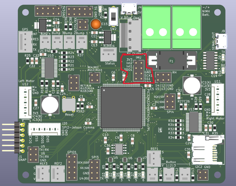
Main Board with IMU Pins Highlighted

Parts

16
QtyValueFootprintReferences
30.1uFCapacitor_SMD:C_0805_2012Metric_Pad1.18x1.45mm_HandSolderC1, C2, C4
31M 0.1%Resistor_SMD:R_0805_2012Metric_Pad1.20x1.40mm_HandSolderR1, R2, R3
3MountingHoleMountingHole:MountingHole_3.2mm_M3H1, H2, H3
110uFCapacitor_SMD:C_0805_2012Metric_Pad1.18x1.45mm_HandSolderC3
11k 1%Resistor_SMD:R_0805_2012Metric_Pad1.20x1.40mm_HandSolderR5
147k 0.1%Resistor_SMD:R_0805_2012Metric_Pad1.20x1.40mm_HandSolderR4
1Conn_01x03_PinConnector_PinHeader_2.54mm:PinHeader_1x03_P2.54mm_VerticalJ1
1ENS130CO_Sensor_library:ENS130U1
1SMMBFJ175LT1GCO_Sensor_library:SOT-23_ONS-MU3
1TP5552-VRCO_Sensor_library:VS1MSOP-8-A_TPK-MU2

Questions

How big is the CO Sensor PCB?

It measures 27.3 × 29.4 mm and has 2 copper layers, 1.65 mm thick.

What parts does the CO Sensor use?

16 parts, built around the TP5552-VR. The full list of its parts is on this page, with links to each part's symbol and footprint where PCBKit's library has them.

Where can I download the CO Sensor KiCad files?

From the satomm1/Robot repository on GitHub, at the commit this page was made from: the board is Electrical/CO_Sensor/CO_Sensor.kicad_pcb and its schematic Electrical/Archives/V0.1/MainBoard/Buttons.kicad_sch. PCBKit opens the board in the browser, with nothing to install.

Can I use the CO Sensor design in my own project?

Its repository publishes it under the MIT licence: you may reuse it on that licence's terms (keep the author's notice, and for a copyleft licence share your changes alike).

More from satomm1/Robot

8
  • 4 layers100 × 86.3 mmArchives, the printed circuit board in 3D

    Archives

    satomm1/Robot

    This directory contains the electrical schematic for a breakout board for the Bosch BMI323 6-axis IMU. This IMU provides a 16 bit digital triaxial accelerometer, a 16 bit digital triaxial gyroscope, and a 16 bit digital…

    138 partsMIT
  • 4 layers100 × 86.3 mmArchives, the printed circuit board in 3D

    Archives

    satomm1/Robot

    This directory contains the electrical schematic for a breakout board for the Bosch BMI323 6-axis IMU. This IMU provides a 16 bit digital triaxial accelerometer, a 16 bit digital triaxial gyroscope, and a 16 bit digital…

    137 partsMIT
  • 2 layers41.5 × 31.6 mmMCU DSP, the printed circuit board in 3D

    MCU DSP

    satomm1/Robot

    This directory contains the electrical schematic for a breakout board for the Bosch BMI323 6-axis IMU. This IMU provides a 16 bit digital triaxial accelerometer, a 16 bit digital triaxial gyroscope, and a 16 bit digital…

    23 partsMIT
  • 2 layers19.3 × 14.2 mmEnvironmentSensor2, the printed circuit board in 3D

    EnvironmentSensor2

    satomm1/Robot

    This directory contains the electrical schematic for a breakout board for the Bosch BMI323 6-axis IMU. This IMU provides a 16 bit digital triaxial accelerometer, a 16 bit digital triaxial gyroscope, and a 16 bit digital…

    11 partsMIT
  • 2 layers26.5 × 6.5 mmReflectiveSensor, the printed circuit board in 3D

    ReflectiveSensor

    satomm1/Robot

    This directory contains the electrical schematic for a breakout board for the Bosch BMI323 6-axis IMU. This IMU provides a 16 bit digital triaxial accelerometer, a 16 bit digital triaxial gyroscope, and a 16 bit digital…

    7 partsMIT
  • 2 layers26.5 × 23.9 mmIMU Breakout, the printed circuit board in 3D

    IMU Breakout

    satomm1/Robot

    This directory contains the electrical schematic for a breakout board for the Bosch BMI323 6-axis IMU. This IMU provides a 16 bit digital triaxial accelerometer, a 16 bit digital triaxial gyroscope, and a 16 bit digital…

    7 partsMIT
  • 2 layers18.3 × 16.7 mmEnvironmentSensor, the printed circuit board in 3D

    EnvironmentSensor

    satomm1/Robot

    This directory contains the electrical schematic for a breakout board for the Bosch BMI323 6-axis IMU. This IMU provides a 16 bit digital triaxial accelerometer, a 16 bit digital triaxial gyroscope, and a 16 bit digital…

    6 partsMIT
  • 2 layers20.8 × 15 mmMicrophone, the printed circuit board in 3D

    Microphone

    satomm1/Robot

    This directory contains the electrical schematic for a breakout board for the Bosch BMI323 6-axis IMU. This IMU provides a 16 bit digital triaxial accelerometer, a 16 bit digital triaxial gyroscope, and a 16 bit digital…

    5 partsMIT

Similar boards

  • 2 layers140.5 × 30 mmType e, the printed circuit board in 3D

    Type e

    google/mozc-devices

    Circuit diagrams and firmware source code for Gboard DIY keyboards

    16 parts3kApache-2.0
  • 2 layers41.4 × 14.5 mmU2f zero, the printed circuit board in 3D

    U2f zero

    conorpp/u2f-zero

    U2F USB token optimized for physical security, affordability, and style

    16 parts2.4k
  • 2 layers122 × 37 mmV0-UmbilicalBoard, the printed circuit board in 3D

    V0-UmbilicalBoard

    VoronDesign/Voron-Hardware

    Cool Hardware designed by the Voron Design group

    16 parts1.1kGPL-3.0
  • 2 layers152 × 57.6 mmVideoslotadapter, the printed circuit board in 3D

    Videoslotadapter

    hoglet67/RGBtoHDMI

    Bare-metal Raspberry Pi project that provides pixel-perfect sampling of Retro Computer RGB/YUV video and conversion to HDMI

    16 parts1kGPL-3.0
  • 2 layers36 × 63.4 mmSmart ringfinal layout, the printed circuit board in 3D

    Smart ringfinal layout

    hackclub/OnBoard

    💡 Join 1,000 teenagers and make your first PCB with a $100 grant!

    16 parts915
  • 2 layers60 × 40 mmHASwitchPlate, the printed circuit board in 3D

    HASwitchPlate

    aderusha/HASwitchPlate

    LCD touchscreen for Home Automation

    16 parts738MIT
  • 2 layers21.1 × 26.9 mmDemo, the printed circuit board in 3D

    Demo

    easyw/kicadStepUpMod

    kicadStepUp: ECAD to MCAD FreeCAD WorkBench

    16 parts704