4 layers91.7 × 66.8 mm
Pico expansion board
eamars/RaspberryPi-Pico-Motor-Expansion-Board
A raspberry pi pico expansion board designed for OpenTrickler project
57 parts18GPL-3.0

 eamars/RaspberryPi-Pico-Motor-Expansion-Board18
A raspberry pi pico expansion board designed for OpenTrickler project
Pico expansion board is an open-source printed circuit board by eamars, from the eamars/RaspberryPi-Pico-Motor-Expansion-Board repository on GitHub, published under the GPL-3.0 licence. It is a 4-layer board of 91.7 × 66.8 mm with 68 parts on 93 nets, routed with 401 tracks and 59 vias.
It is built around the 74LVC1G125, MAX3232ID and CH224K, with the TPS5450DDA, CAT24C256LI and SS54 among its other parts. Its parts include 18 capacitors, 16 resistors, 13 connectors, 9 ICs and 6 diodes. It belongs with the RP2040 boards of this library.


[!Note] You can purchase the board directly from Mellow 3D and ship worldwide now. LINK: https://www.aliexpress.com/item/1005008080766173.html
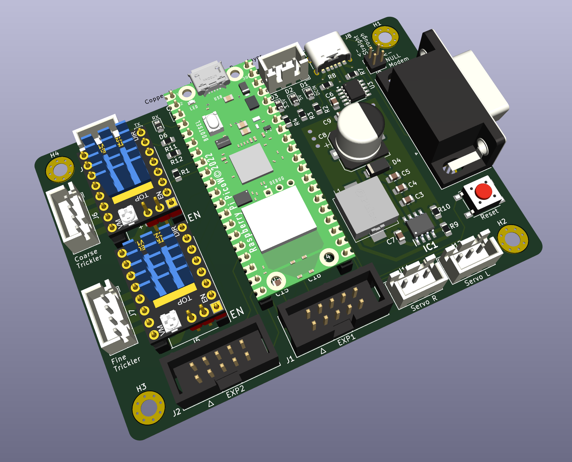
The Raspberry Pi Pico Motor Expansion Board V2 vis designed to be used as the controller for OpenTrickler. The board is designed to trickle certain amount of charges (e.g, gun powder) from the reservoir by reading measurements from the attached precision digital balance and actuate corresponding motors.
Join our discord server for help and development information.
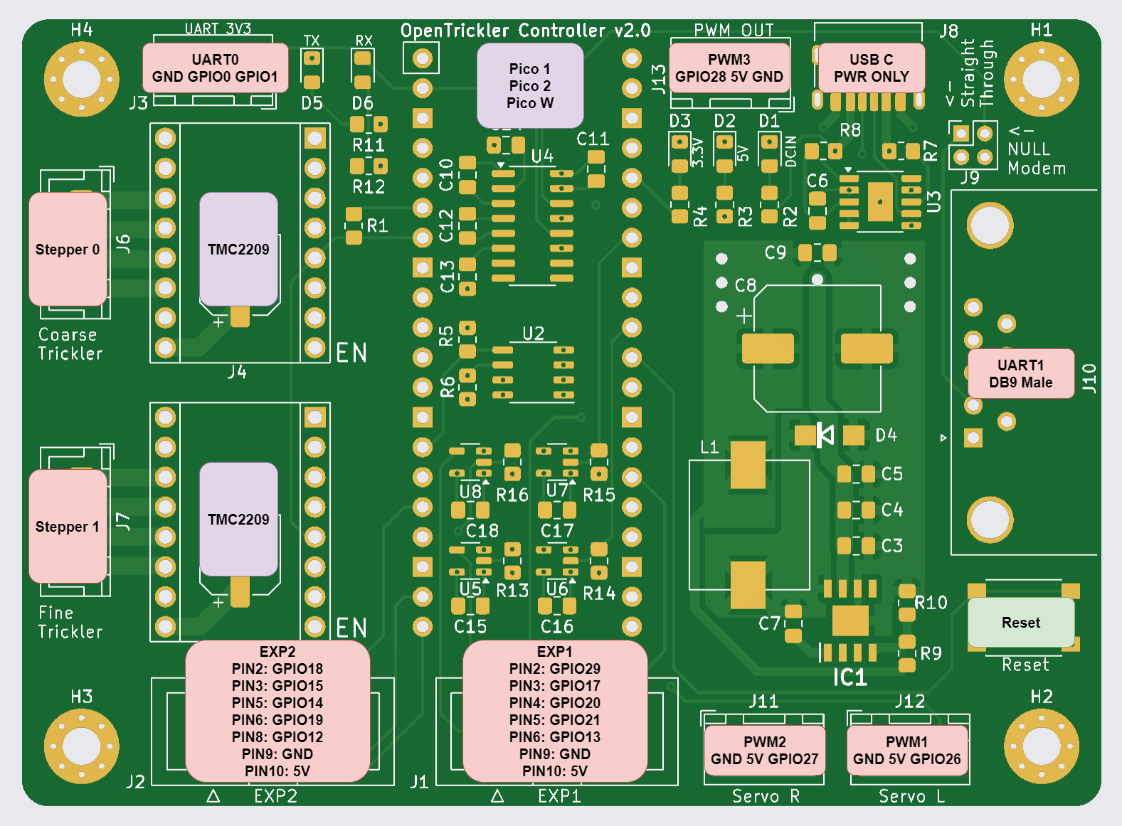
The PINOUT diagram is shown below. To pair with the OpenTrickler controller software, you need to use Pico W as the main controller.
EXP1/EXP2: To be paired to RepRap 12864 LED display and the compatible display module.
PWM1/PWM2/PWM3: Can be used to connect with SG90/MG90/S0009M servo motors, or Neopixel RGB LEDs (WS2812)
UART0: Can be used to connect with external serial to UART adapter, when UART1 is not used.
UART1: Compatible with RS232 devices.
The board is designed to be power from USB-C Charger or power banks. The charger MUST support minimum 12V and 2A output.
NOTE: The board is NOT compatible with USB-A or USB-B charger or adapter cable. USB-C cable and charger must be used.
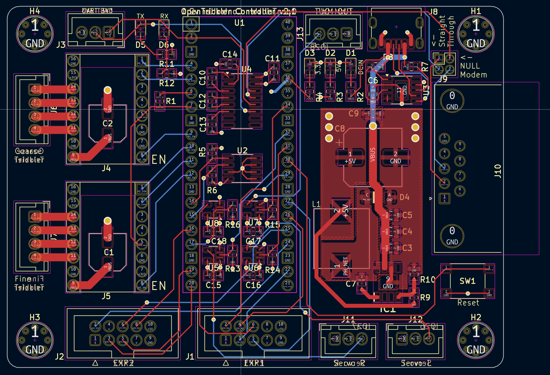
The board is designed to be manufactured with 4 layer PCB. Traces are placed at top and bottom layers. Two mid layers are for power (Vcc, 5V) and GND.
The board is designed with hand soldering in mind. The board can also be manufactured by SMT.
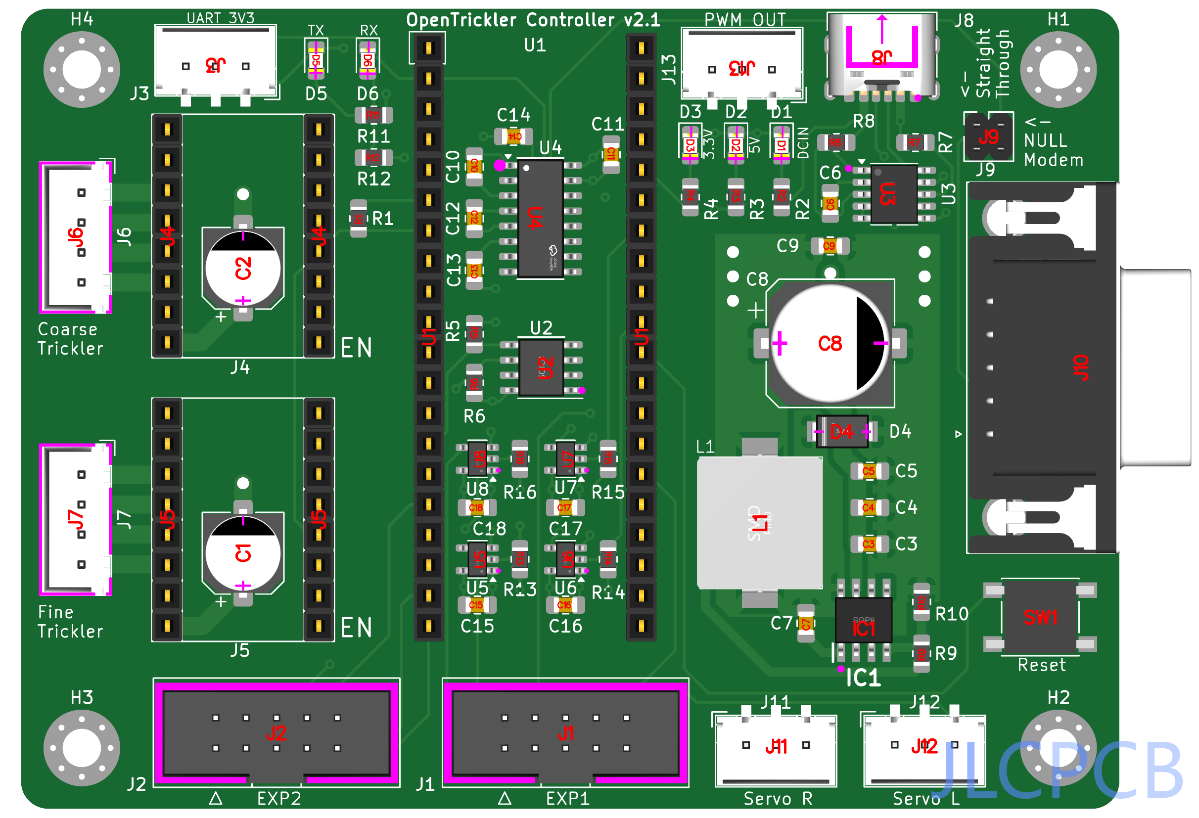
BOM and gerber files are provided under production directory. Instructions are also provided regarding the PCB contract manufactoring with JLCPCB.
There are several components on JLCPCB that can be out of stock from time to time. The table below shows the substitution of those components.
| Designator | Part Number | Primary LCSC Part Number | Substitution LCSC Part Number |
|---|---|---|---|
| U2 | CAT24C256 (SOIC-8) | C79987 | C81195 (CAT24C128) |
| IC1 | TPS5450 (SOP-8) | C114425 | |
| U3 | CH224K (ESSOP-10) | C970725 | |
| L1 | 15uH Inductor (10x11) | C151872 | C439295 C5123010 |
| U4 | MAX3232 (SOIC-16) | C18261 | |
| J10 | DB9 Male | C426221 | C141880 |
| U5,U6,U7,U8 | 74LVC1G125 | C23654 |
None
| Qty | Value | Footprint | References |
|---|---|---|---|
| 9 | 100nF | Capacitor_SMD:C_0805_2012Metric_Pad1.18x1.45mm_HandSolder | C10, C11, C12, C13, C14, C15, C16, C17, C18 |
| 5 | 4.7k | Resistor_SMD:R_0805_2012Metric_Pad1.20x1.40mm_HandSolder | R2, R13, R14, R15, R16 |
| 4 | 74LVC1G125 | Package_TO_SOT_SMD:SOT-23-5 | U5, U6, U7, U8 |
| 4 | ~ | MountingHole:MountingHole_3.2mm_M3_Pad_Via | H1, H2, H3, H4 |
| 3 | 10K | Resistor_SMD:R_0805_2012Metric_Pad1.20x1.40mm_HandSolder | R5, R6, R9 |
| 3 | 10nF | Capacitor_SMD:C_0805_2012Metric_Pad1.18x1.45mm_HandSolder | C5, C7, C9 |
| 3 | 1k | Resistor_SMD:R_0805_2012Metric_Pad1.20x1.40mm_HandSolder | R8, R11, R12 |
| 3 | Conn_01x03_Pin | Connector_JST:JST_XH_B3B-XH-A_1x03_P2.50mm_Vertical | J11, J12, J13 |
| 3 | GREEN | Diode_SMD:D_0805_2012Metric_Pad1.15x1.40mm_HandSolder | D1, D2, D3 |
| 2 | 100uF | Capacitor_SMD:CP_Elec_6.3x7.7 | C1, C2 |
| 2 | 4.7uF | Capacitor_SMD:C_0805_2012Metric_Pad1.18x1.45mm_HandSolder | C3, C4 |
| 1 | 10k | Resistor_SMD:R_0805_2012Metric_Pad1.20x1.40mm_HandSolder | R7 |
| 1 | 15uH | library:Power Inductor 10x11 | L1 |
| 1 | 1K | Resistor_SMD:R_0805_2012Metric_Pad1.20x1.40mm_HandSolder | R1 |
| 1 | 1u | Capacitor_SMD:C_0805_2012Metric_Pad1.18x1.45mm_HandSolder | C6 |
| 1 | 3.16K | Resistor_SMD:R_0805_2012Metric_Pad1.20x1.40mm_HandSolder | R10 |
| 1 | 300 | Resistor_SMD:R_0805_2012Metric_Pad1.20x1.40mm_HandSolder | R4 |
| 1 | 330uF | Capacitor_SMD:CP_Elec_10x10.5 | C8 |
| 1 | 680 | Resistor_SMD:R_0805_2012Metric_Pad1.20x1.40mm_HandSolder | R3 |
| 1 | BLUE | Diode_SMD:D_0805_2012Metric_Pad1.15x1.40mm_HandSolder | D6 |
| 1 | CAT24C256 | Package_SO:SO-8_3.9x4.9mm_P1.27mm | U2 |
| 1 | CH224K | Package_SO:SSOP-10-1EP_3.9x4.9mm_P1mm_EP2.1x3.3mm | U3 |
| 1 | Conn_01x03_Socket | Connector_JST:JST_XH_B3B-XH-A_1x03_P2.50mm_Vertical | J3 |
| 1 | Conn_02x02_Odd_Even | Connector_PinHeader_2.00mm:PinHeader_2x02_P2.00mm_Vertical | J9 |
| 1 | EXP1 | Connector_IDC:IDC-Header_2x05_P2.54mm_Vertical | J1 |
| 1 | EXP2 | Connector_IDC:IDC-Header_2x05_P2.54mm_Vertical | J2 |
| 1 | MAX3232 | Package_SO:SOIC-16_3.9x9.9mm_P1.27mm | U4 |
| 1 | Motor 1 | Connector_JST:JST_XH_B4B-XH-A_1x04_P2.50mm_Vertical | J6 |
| 1 | Motor 2 | Connector_JST:JST_XH_B4B-XH-A_1x04_P2.50mm_Vertical | J7 |
| 1 | Pico | RPI_Pico:RPi_Pico_FootprintOnly | U1 |
| 1 | RED | Diode_SMD:D_0805_2012Metric_Pad1.15x1.40mm_HandSolder | D5 |
| 1 | SS54 | library:DO-214AC | D4 |
| 1 | SW_Push | Button_Switch_SMD:SW_Push_1P1T_NO_6x6mm_H9.5mm | SW1 |
| 1 | TMC2209 Motor 1 | library:Conn_StepStick_smaller_hole | J4 |
| 1 | TMC2209 Motor 2 | library:Conn_StepStick_smaller_hole | J5 |
| 1 | TPS5450DDA | library:SOIC127P600X170-9N | IC1 |
| 1 | USB_C_Receptacle_USB2.0_14P | Connector_USB:USB_C_Receptacle_HRO_TYPE-C-31-M-17 | J8 |
| 1 | ~ | Connector_Dsub:DSUB-9_Male_Horizontal_P2.77x2.84mm_EdgePinOffset7.70mm_Housed_MountingHolesOffset9.12mm | J10 |
eamars/RaspberryPi-Pico-Motor-Expansion-Board
A raspberry pi pico expansion board designed for OpenTrickler project

eamars/RaspberryPi-Pico-Motor-Expansion-Board
A raspberry pi pico expansion board designed for OpenTrickler project

Icey7122/AM32_AI8051U
Using PWMA to output 3 sets of complementary PWM for driving MOSFEET, Using PWMB for capturing external throttle signals, Using ADC to sample voltage and current, for low voltage protection and over current…

Cloud-Lightning/ESP32_Distribution_board
text BUS+ / GND |-- 7 x XT30 原始总线电源分配 | -- TPS5450DDA --> +5V --> AMS1117-3.3 --> +3.3V | | | -- ESP32、CH340K、逻辑电路 -- 5V 外设接口

mgalleguilloscespedes-png/proyectro-stm32
en mi afán por el diseño 3d y la electrónica decidí crear mi propia versión de una placa controladora para impresora 3d, basándome en el microcontrolador stm32h723zet6 y la pcb de bigtreetech manta mp8

KarlZeilhofer/htl-loetregler-mini
Einfacher Regler für JBC Lötspitzen der Serie T210, T245 und T470, Weller RT-Spitzen und TS100-Spitzen sollten auch funktionieren.

mortens-lab/HUB75-PICO-shield
HUB75 matrix display shield controlled by a Raspberry Pi Pico W


SEAS2025/mmwave-deer-scan
mmWave FMCW radar deer detection for roadside ambulance safety

It measures 91.7 × 66.8 mm and has 4 copper layers, 0.19 mm thick.
68 parts, built around the 74LVC1G125, MAX3232ID, CH224K and TPS5450DDA. The full list of its parts is on this page, with links to each part's symbol and footprint where PCBKit's library has them.
From the eamars/RaspberryPi-Pico-Motor-Expansion-Board repository on GitHub, at the commit this page was made from: the board is motor_expansion_board_v2/pcb/pico_expansion_board.kicad_pcb and its schematic archive/motor_expansion_board/pcb/pico_expansion_board.kicad_sch. PCBKit opens the board in the browser, with nothing to install.
Its repository publishes it under the GPL-3.0 licence: you may reuse it on that licence's terms (keep the author's notice, and for a copyleft licence share your changes alike).