4 layers91.7 × 66.8 mm
Pico expansion board
eamars/RaspberryPi-Pico-Motor-Expansion-Board
A raspberry pi pico expansion board designed for OpenTrickler project
68 parts18GPL-3.0

 Icey7122/AM32_AI8051U17
Using PWMA to output 3 sets of complementary PWM for driving MOSFEET, Using PWMB for capturing external throttle signals, Using ADC to sample voltage and current, for low voltage protection and over current…
Am32stc8051u is an open-source printed circuit board by Icey7122, from the Icey7122/AM32_AI8051U repository on GitHub. It is a 2-layer board of 68.5 × 84.2 mm with 110 parts on 102 nets, routed with 522 tracks and 292 vias.
It is built around the CH330N, EG2181 and MT3608, with the TPS5450DDA, RT9048GSP and SS54 among its other parts. Its parts include 34 resistors, 32 capacitors, 19 diodes, 9 ICs and 6 transistors. It belongs with the 8051 (CH55x, STC, AT89) boards of this library.


The AM32 firmware has been ported to the 80251 platform, and the controller has chosen as AI8051U. It can be compiled on Keil C251. At the same time, the bootloader program has been ported, and tool of Esc_Config_Tool_1_82_WIN can be used to configure and upgrade firmware for ESC.
The resources of MCU(datasheet) are shown in the following figure,You can see that it has many peripheral resources.For more information, you can refer to the STC
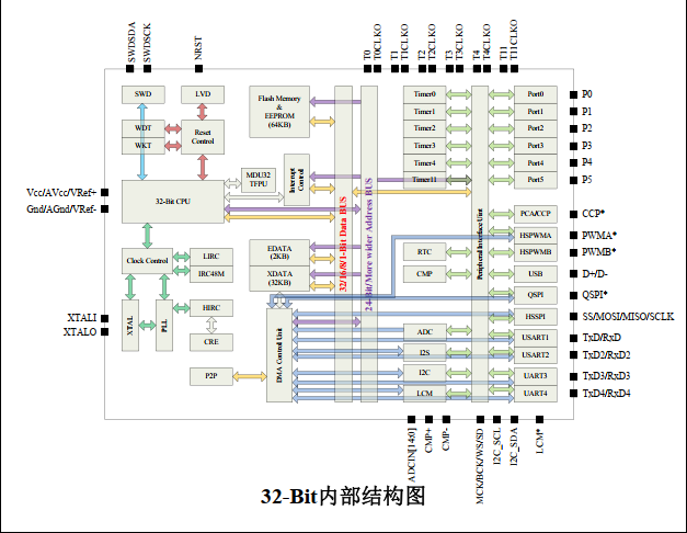
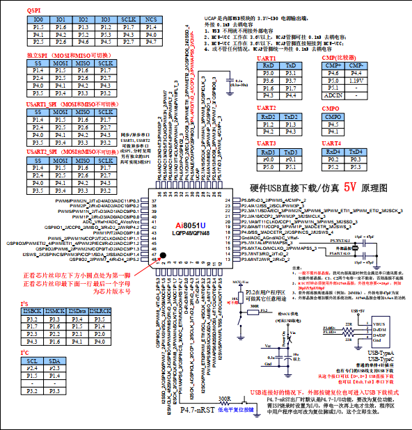
Using PWMA to output 3 sets of complementary PWM for driving MOSFEET, Using PWMB for capturing external throttle signals, Using ADC to sample voltage and current, for low voltage protection and over current protection(But I'm not done yet). Using internal OPA and BEMF to estimate rotor position. TMR0 and TMR1 is used to calculate commutation time and motor timing.TMR2 is used for the serial port. TMR3 and TMR11 are used for the delay function (in fact, only one is needed). TMR4 is used to complete some periodic tasks.

AH AL BH BL CH CL: PWMA outputs;
INPUT: PWMB used to capture external throttle signals;
A_BEMF: A-Phase BEMF, connect to P46;
B_BEMF: B-Phase BEMF, connect to P51;
C_BEMF: C-Phase BEMF, connect to P50;
CC_BEMF: Neutral point BEMF, connect to P45/P44(Note that for this mcu, P45 and P44 are the same pins);
ADC_V: Voltage sampling channel;
ADC_I: Current sampling channel;
In order to unify the interrupt entry of OPA, the outputs of OPA are merged into P41, Using pin interrupts of P41 for zero crossing comparison processing.
P30 and P31 are used to download bootloader via STC-LINK1, UART or internal USB.
For detailed information, please refer to the schematic diagram.
For empty chips, BootLoader needs to be flashed via STC-LINK1, UART or internal USB, Connect according to the diagram below.
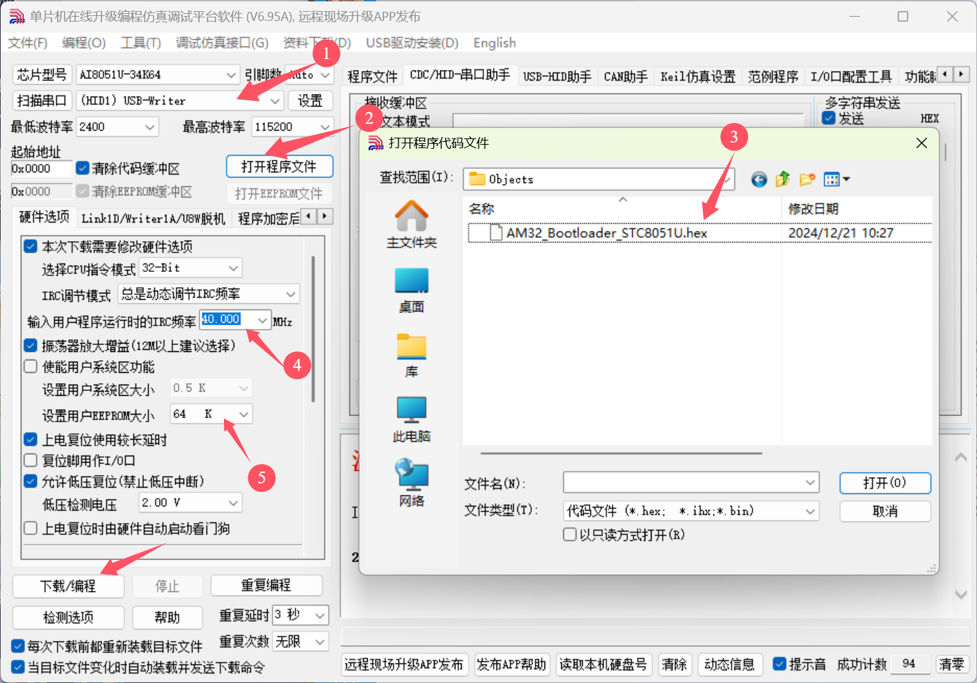
Open the Bootloader project using AIapp-ISP and download it directly after compilation.
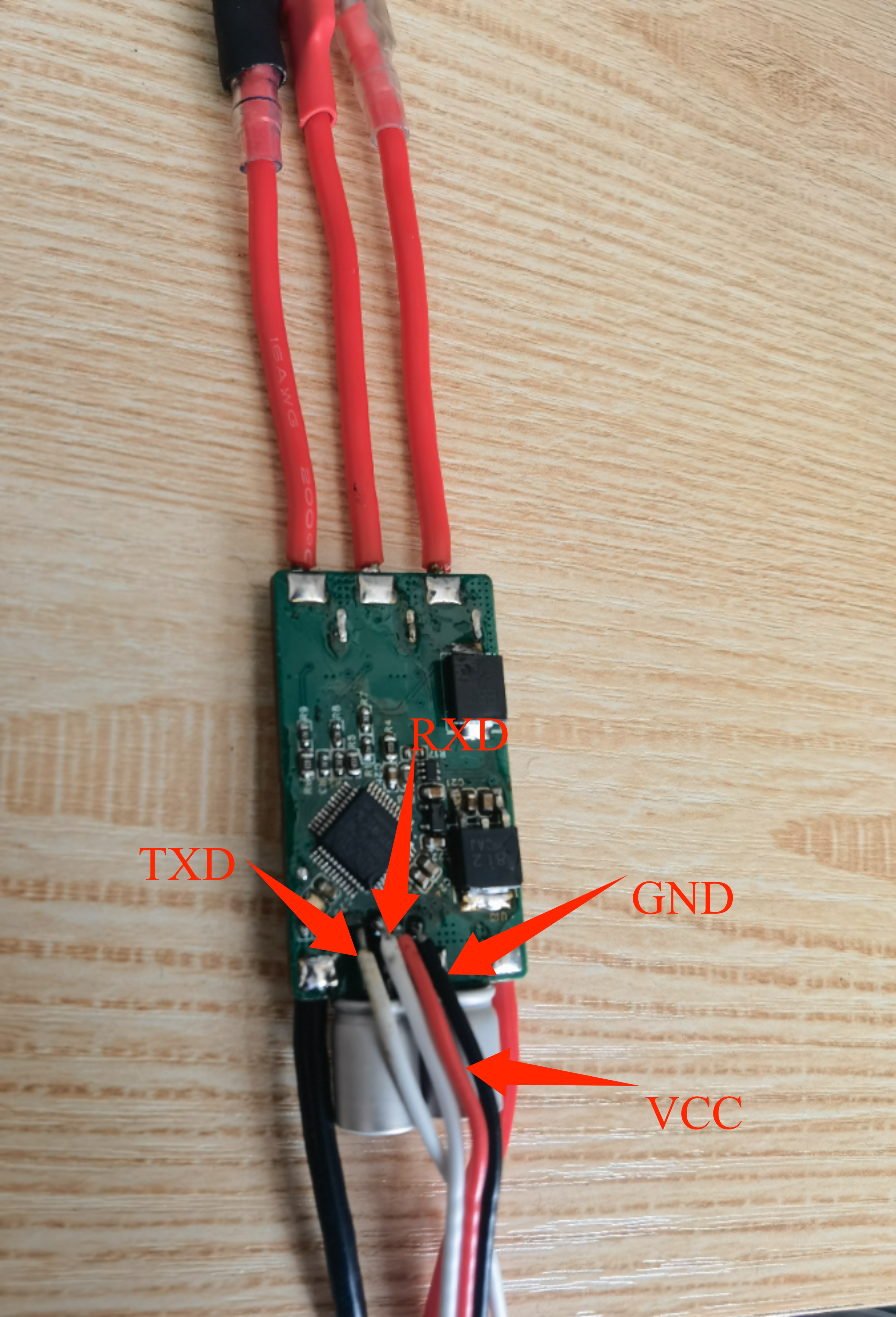
Use a one-wire serial port(You can connect the RX and TX of the USB to serial chip,such as CH340, together and then connect them to the board) to connect to ESC and use tools to configure and update firmware. I used CH340 to perfom, and the wiring is shown in the following figure.
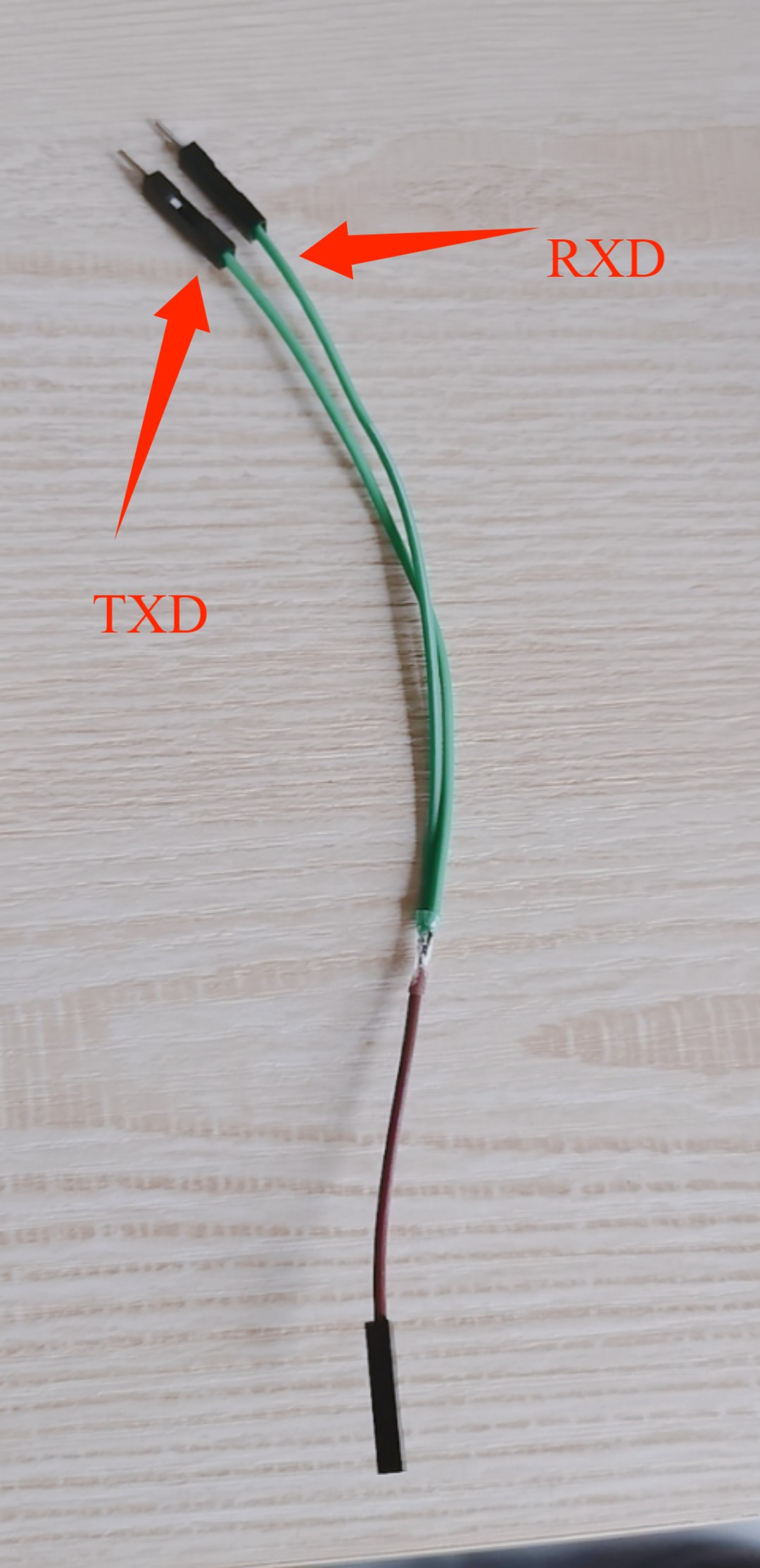
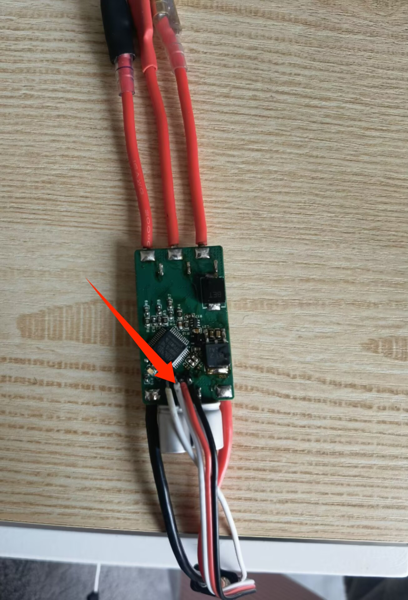
If the Bootloader is burned correctly, Open the configuration tool Esc_Config_Tool_1_82_WIN.exe and power on the ESC. Follow the steps in the following figure to click. When connecting for the first time, 'No EEprom' will be displayed!
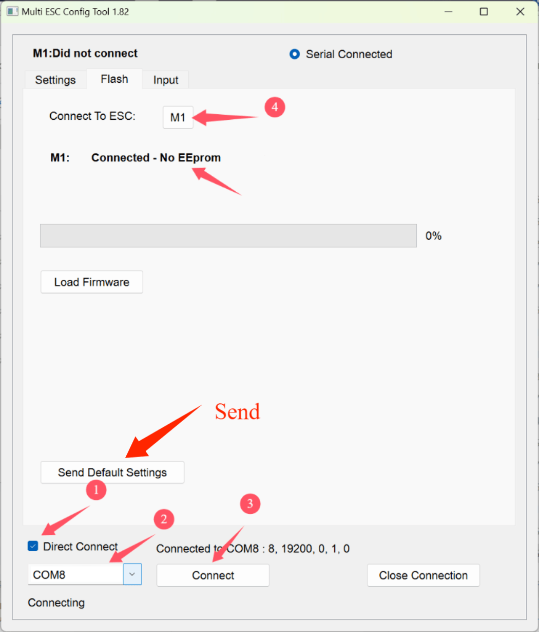
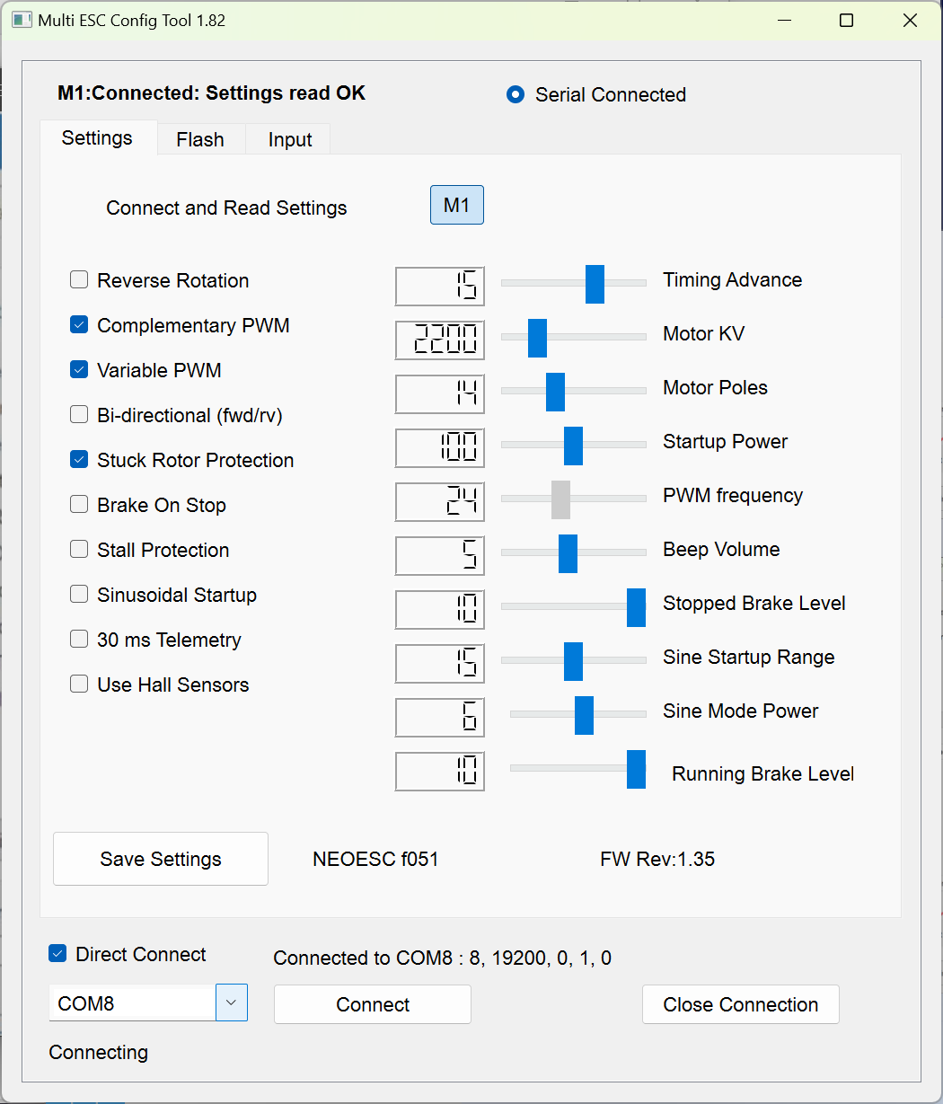
Directly click on Send Default Settings below to burn the default values. After successful burning, power on again. Connect again and click M1. The default parameters we just burned will be displayed.
Flashing firmware and configurations
The firmware can be compiled using Keil C251, and the compiled firmware is in the \Objects folder.
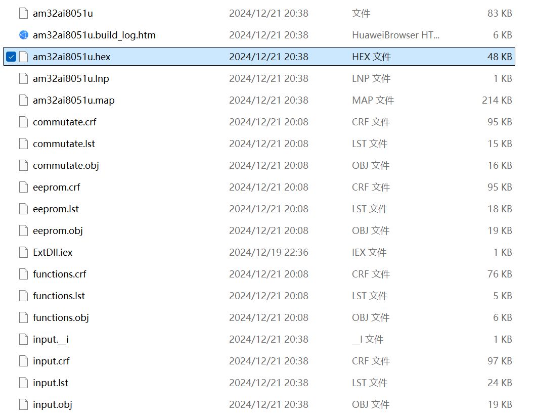
Open the HEX file with a text editor.I prefer to use VScode.To support HEX file editing, you need to install the Hex Editor or Intel HEX format plug-in. The plug-in can be installed in the extension market. After installation, open the HEX file.
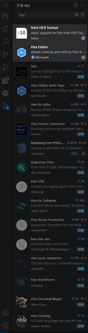
In this HEX file, please pay attention to the first line.
:03000000023E5865
You should change the value of the 0000 to 1000 and the value of the 65 to 55. Then save the file.
:03100000023E5855
Note that the value of the 0000 is the starting address of the program, and the value of the 65 is the checksum. The value of the 1000 is the starting address of the program after the bootloader is burned. The value of the 55 is the new checksum. The starting address of the program after the bootloader is burned is 0x1000, so the value of the 0000 is changed to 1000. The checksum is calculated by adding all the data in the line except the starting colon and the checksum itself, and then taking the two's complement of the last byte of the sum. The value of the 65 is changed to 55. The specific calculation method can be found in the link.
If you use VScode with the plug-in, you can directly click on the address value to modify it, and the plug-in may automatically calculate the new checksum.
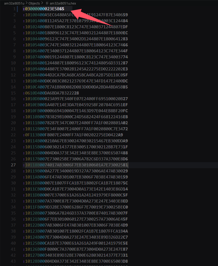
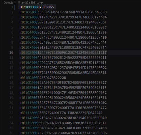
Returning to the FLASH interface of the tool, we click on Load Firmware, select the firmware we just modified, and the FLash Firmware button will pop up. Click to start updating the program.
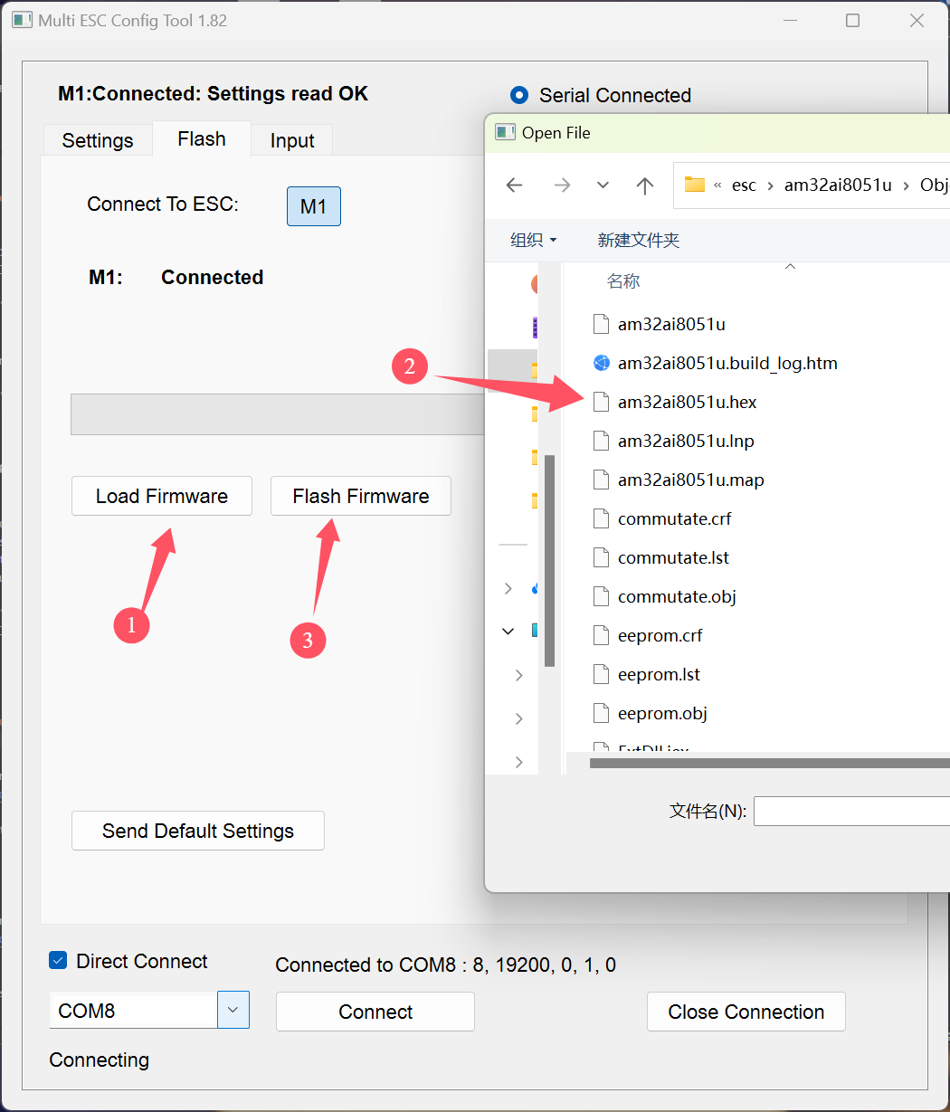
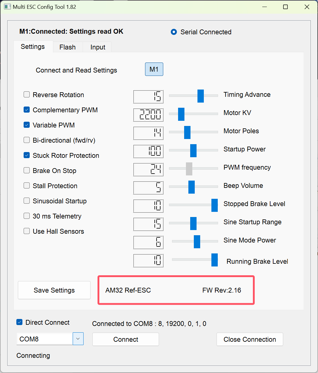
After the update is completed, power on again and connect ESC again to configure ESC. The specific meaning of configuration values can be found in the following links.
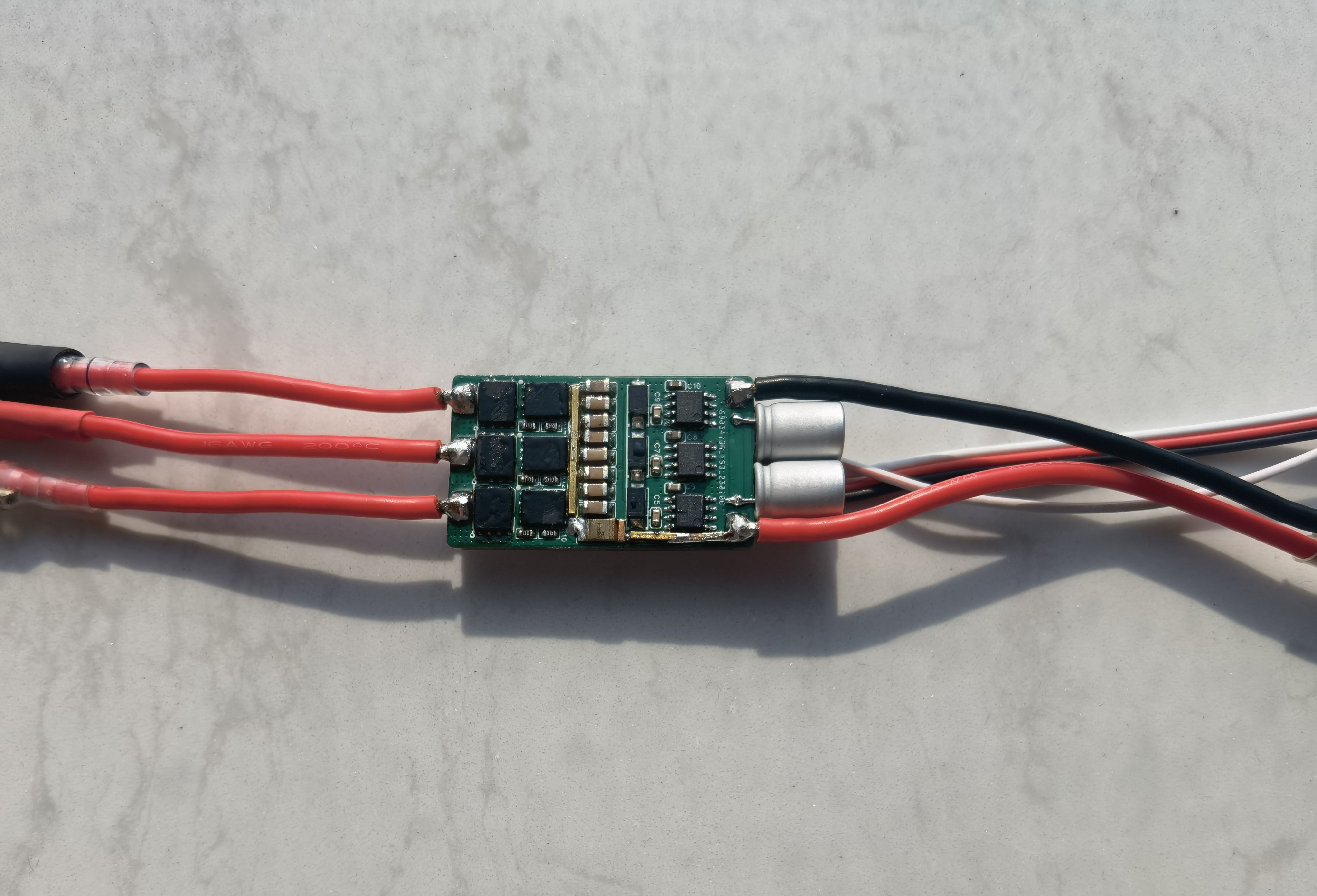
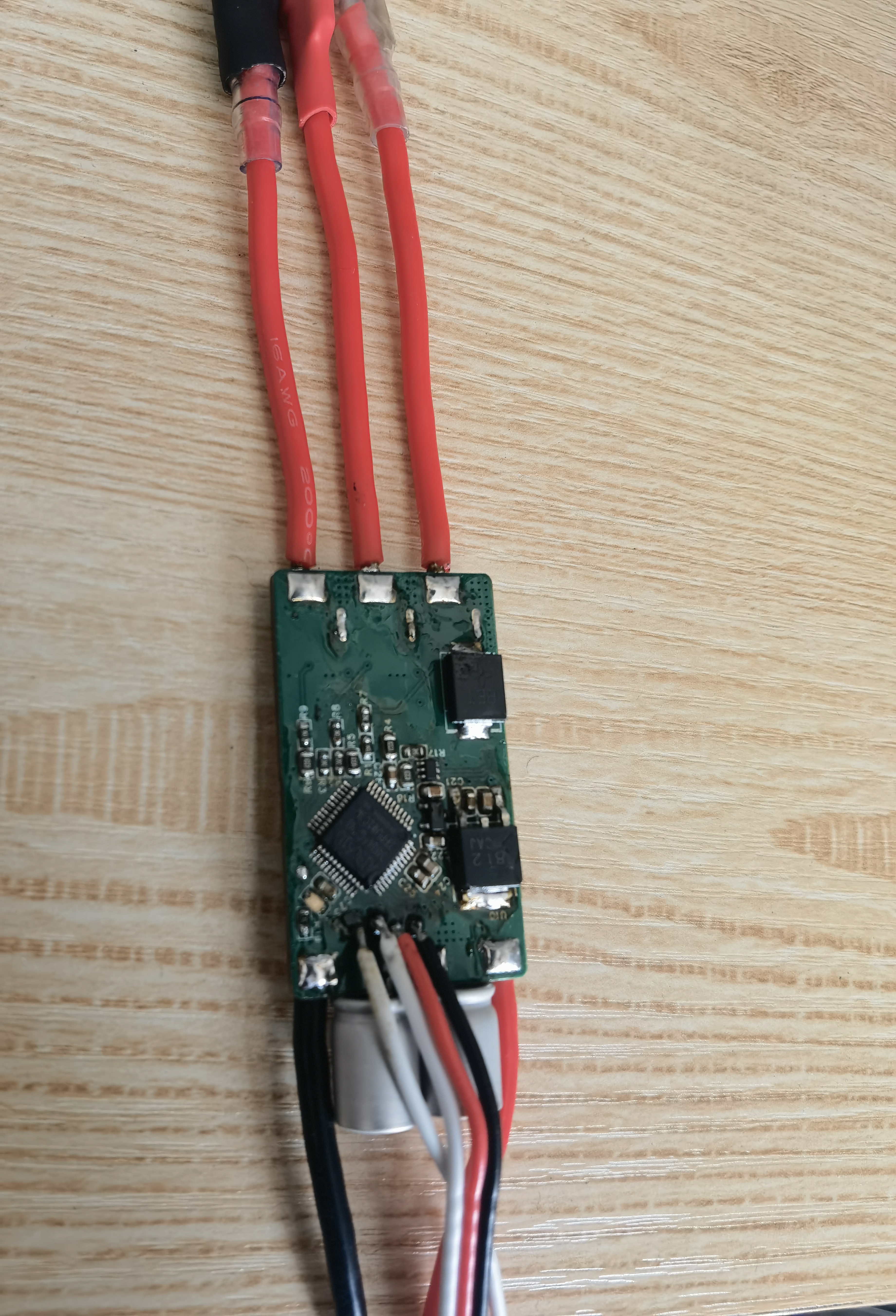
The circuit design is located in docs: pcb, and the design is carried out using KiCAD, please note that the design is not particularly reasonable, please refer to it carefully.(Now I redesign the PCB on LCEDA, and the new PCB project also in docs folder.)
New design:
The version I ported is V2.16, which supports signals such as dshot300, dshot600, and PWM.(But for some reason, I only implemented PWM, dshot can't be used).
| Qty | Value | Footprint | References |
|---|---|---|---|
| 11 | SS54 | Diode_SMD:D_SMA_Handsoldering | D1, D4, D5, D6, D9, D10, D11, D14, D15, D16, D17 |
| 9 | 10K | PCM_Resistor_SMD_AKL:R_0603_1608Metric_Pad0.98x0.95mm_HandSolder | R5, R6, R7, R8, R9, R10, R17, R20, R30 |
| 9 | C | Capacitor_SMD:C_1206_3216Metric_Pad1.33x1.80mm_HandSolder | C6, C7, C8, C11, C12, C13, C16, C17, C18 |
| 7 | 0.1uF | Capacitor_SMD:C_0603_1608Metric_Pad1.08x0.95mm_HandSolder | C1, C19, C20, C28, C29, C30, C31 |
| 6 | 10R | PCM_Resistor_SMD_AKL:R_0603_1608Metric_Pad0.98x0.95mm_HandSolder | R11, R12, R13, R14, R15, R16 |
| 6 | 1K | PCM_Resistor_SMD_AKL:R_0603_1608Metric_Pad0.98x0.95mm_HandSolder | R2, R3, R4, R27, R28, R29 |
| 6 | 1N5819 | Diode_SMD:D_SOD-323_HandSoldering | D2, D3, D7, D8, D12, D13 |
| 6 | TPH1R005PL | PCM_Package_SON_AKL:Infineon_PG-TDSON-8 | Q1, Q2, Q3, Q4, Q5, Q6 |
| 4 | 5.1K | Resistor_SMD:R_0603_1608Metric_Pad0.98x0.95mm_HandSolder | R23, R24, R31, R32 |
| 4 | Conn_01x03_Pin | Connector_PinHeader_2.54mm:PinHeader_1x03_P2.54mm_Vertical | J2, J3, J4, J5 |
| 3 | 10uF | Capacitor_SMD:C_0603_1608Metric_Pad1.08x0.95mm_HandSolder | C2, C24, C26 |
| 3 | C | Capacitor_SMD:C_0805_2012Metric_Pad1.18x1.45mm_HandSolder | C4, C9, C14 |
| 3 | C | Capacitor_SMD:C_0603_1608Metric_Pad1.08x0.95mm_HandSolder | C5, C10, C15 |
| 3 | EG2181 | Package_SO:SOP-8_5.28x5.23mm_P1.27mm | U2, U3, U4 |
| 2 | 10K | Resistor_SMD:R_0603_1608Metric_Pad0.98x0.95mm_HandSolder | R33, R34 |
| 2 | 10uH | PCM_Inductor_SMD_Handsoldering_AKL:L_6.3x6.3_H3 | L1, L2 |
| 2 | 4.7uF | Capacitor_SMD:C_0603_1608Metric_Pad1.08x0.95mm_HandSolder | C21, C27 |
| 2 | LED | LED_SMD:LED_0603_1608Metric_Pad1.05x0.95mm_HandSolder | D18, D19 |
| 2 | SW_Push | Button_Switch_SMD:SW_SPST_CK_RS282G05A3 | SW1, SW2 |
| 2 | USB_C_Receptacle_USB2.0_16P | Connector_USB:USB_C_Receptacle_GCT_USB4105-xx-A_16P_TopMnt_Horizontal | J1, J6 |
| 1 | 0.01uF | Capacitor_SMD:C_0603_1608Metric_Pad1.08x0.95mm_HandSolder | C23 |
| 1 | 0R | PCM_Resistor_SMD_AKL:R_0603_1608Metric_Pad0.98x0.95mm_HandSolder | R1 |
| 1 | 1.11K | PCM_Resistor_SMD_AKL:R_0603_1608Metric_Pad0.98x0.95mm_HandSolder | R19 |
| 1 | 100K | PCM_Resistor_SMD_AKL:R_0603_1608Metric_Pad0.98x0.95mm_HandSolder | R22 |
| 1 | 100nF | Capacitor_SMD:C_0603_1608Metric_Pad1.08x0.95mm_HandSolder | C25 |
| 1 | 1uF | Capacitor_SMD:C_0603_1608Metric_Pad1.08x0.95mm_HandSolder | C3 |
| 1 | 2.6K | PCM_Resistor_SMD_AKL:R_0603_1608Metric_Pad0.98x0.95mm_HandSolder | R18 |
| 1 | 330uF | Capacitor_Tantalum_SMD:CP_EIA-6032-15_Kemet-U_Pad2.25x2.35mm_HandSolder | C22 |
| 1 | 5.1K | PCM_Resistor_SMD_AKL:R_0603_1608Metric_Pad0.98x0.95mm_HandSolder | R26 |
| 1 | 6.38K | PCM_Resistor_SMD_AKL:R_0603_1608Metric_Pad0.98x0.95mm_HandSolder | R21 |
| 1 | CH330N | Package_SO:SOIC-8_3.9x4.9mm_P1.27mm | U9 |
| 1 | C_Polarized | Capacitor_THT:CP_Radial_D10.0mm_P5.00mm | C32 |
| 1 | INA199xxDCK | Package_TO_SOT_SMD:SOT-363_SC-70-6 | U8 |
| 1 | MT3608 | Package_TO_SOT_SMD:SOT-23-6 | U7 |
| 1 | RT9048 | Package_SO:HSOP-8-1EP_3.9x4.9mm_P1.27mm_EP2.3x2.3mm | U6 |
| 1 | R_2512 | PCM_Resistor_SMD_AKL:R_2512_6332Metric | R25 |
| 1 | STC8051U-32Kx | Package_QFP:LQFP-48_7x7mm_P0.5mm | U1 |
| 1 | TPS5450 | Package_SO:SOIC-8-1EP_3.9x4.9mm_P1.27mm_EP2.29x3mm | U5 |
eamars/RaspberryPi-Pico-Motor-Expansion-Board
A raspberry pi pico expansion board designed for OpenTrickler project

Cloud-Lightning/ESP32_Distribution_board
text BUS+ / GND |-- 7 x XT30 原始总线电源分配 | -- TPS5450DDA --> +5V --> AMS1117-3.3 --> +3.3V | | | -- ESP32、CH340K、逻辑电路 -- 5V 外设接口

mgalleguilloscespedes-png/proyectro-stm32
en mi afán por el diseño 3d y la electrónica decidí crear mi propia versión de una placa controladora para impresora 3d, basándome en el microcontrolador stm32h723zet6 y la pcb de bigtreetech manta mp8

szbeni/forcegauge
Traning for climbing. Load cell with HX711 and real time plotting,

mortens-lab/HUB75-PICO-shield
HUB75 matrix display shield controlled by a Raspberry Pi Pico W


SEAS2025/mmwave-deer-scan
mmWave FMCW radar deer detection for roadside ambulance safety

It measures 68.5 × 84.2 mm and has 2 copper layers, 1.6 mm thick.
110 parts, built around the CH330N, EG2181, MT3608 and TPS5450DDA. The full list of its parts is on this page, with links to each part's symbol and footprint where PCBKit's library has them.
From the Icey7122/AM32_AI8051U repository on GitHub, at the commit this page was made from: the board is docs/pcb/kicad/Am32stc8051u.kicad_pcb and its schematic docs/pcb/kicad/Am32stc8051u.kicad_sch. PCBKit opens the board in the browser, with nothing to install.
Its repository states no licence, so its author keeps all rights: ask Icey7122 before reusing the design.