6 layers69.7 × 76.7 mm
Amulet controller
EPFLXplore/XRE_LeggedRobot_HW
PCB designs for Xplore Research's robot dog project
414 parts348Apache-2.0

 aidanbrzezinski/Prism-test
ΛMULET is a high-power brushless motor controller, compatible with the moteus firmware. It was specifically designed to be integrated in EPFL Xplore's Legged Robot actuators.
Amulet controller is an open-source printed circuit board by aidanbrzezinski, from the aidanbrzezinski/Prism-test repository on GitHub. It is a 6-layer board of 69.7 × 76.7 mm with 414 parts on 181 nets, routed with 1,530 tracks and 794 vias.
It is built around the AS5047P-ATSM, AS5048B-HTSP-500 and DRV8353FSRTAR, with the GRJ31CZ72A475KE01L, BAT41KFILM and RCS0402100RFKED among its other parts. Its parts include 138 capacitors, 60 resistors, 25 diodes, 9 transistors and 4 ICs. It belongs with the robots and motor control boards of this library.




ΛMULET is a high-power brushless motor controller, compatible with the moteus firmware. It was specifically designed to be integrated in EPFL Xplore's Legged Robot actuators.
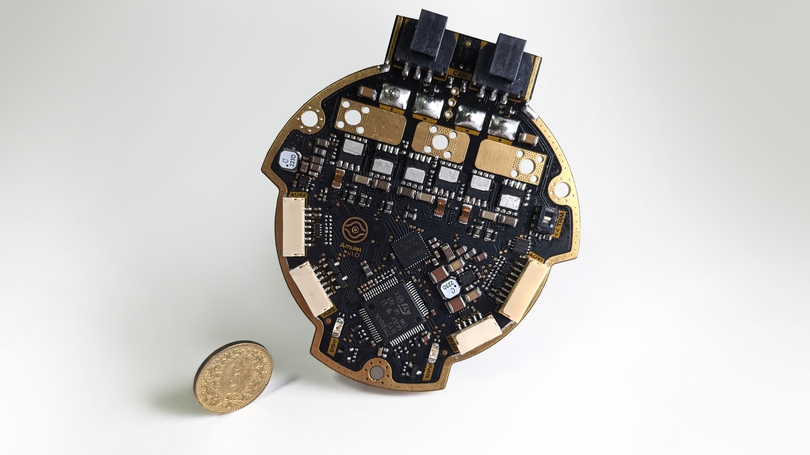
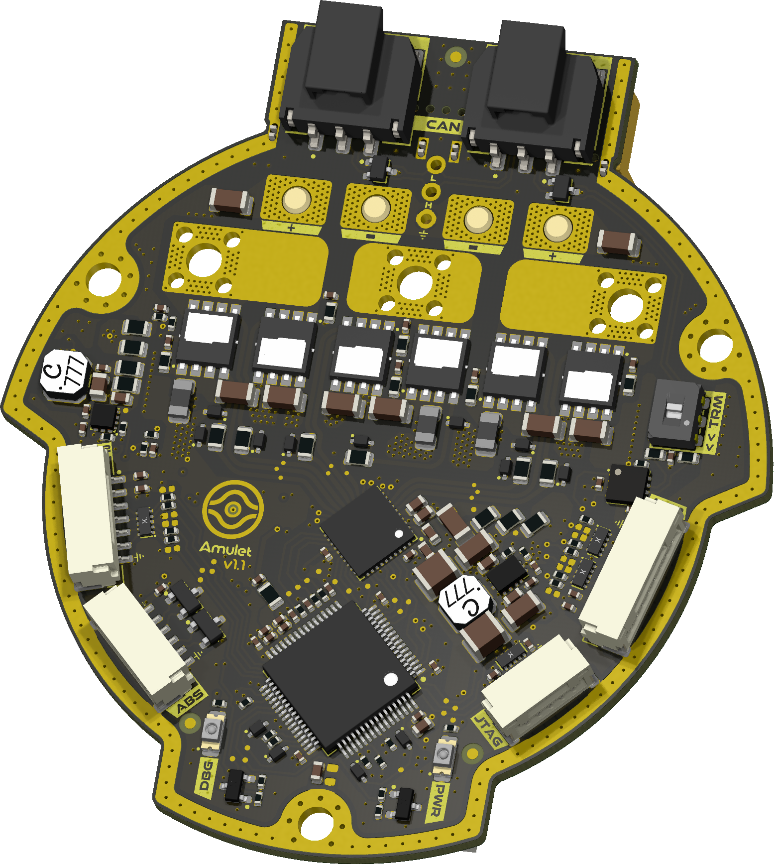
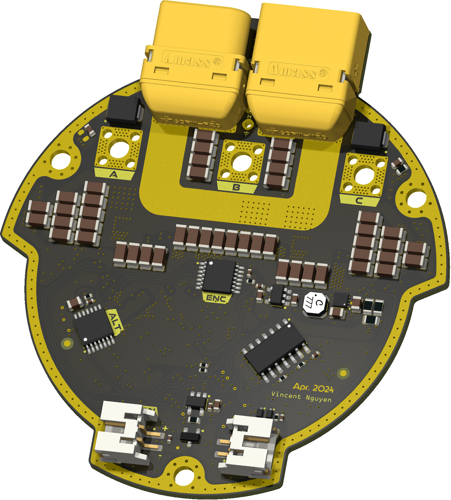
| Parameter | ΛMULET V1.0 |
|---|---|
| Voltage Input | 12-44V |
| Peak Electrical Power | TBD |
| Mass | TBD |
| Peak Phase Current | 100A |
| Communication | 5Mbps CAN-FD |
| Cooling | 12V Fan |
| Positioning | 2x Onboard 14-bit Encoders |
| Control rate | 15-30kHz |
| PWM Switching Rate | 15-60kHz |
| MCU | STM32G474 |
| Dimensions | 69.67 × 76.7 mm |
.
├─ Computations       # Misc calculations
├─ DXF_SVG            # Vector graphics
├─ HTML               # HTML files for generated webpage
├─ Images             # Pictures and renders
│
├─ kibot_resources    # External resources for KiBot
│  ├─ colors          # Color theme for KiCad
│  ├─ fonts           # Fonts used in the project
│  ├─ scripts         # External scripts used with KiBot
│  └─ templates       # Templates for KiBot generated reports
│
├─ kibot_yaml         # KiBot YAML config files
├─ KiRI               # KiRI (PCB diff viewer) files
│
├─ lib                # KiCad footprint and symbol libraries
│  ├─ 3d_models       # Component 3D models
│  ├─ lib_fp          # Footprint libraries
│  └─ lib_sym         # Symbol libraries
│
├─ Logos              # Logos
│
├─ Manufacturing      # Assembly and fabrication documents
│ ├─ Assembly # Assembly documents (BoM, pos, notes)Associated firmware is forked from the moteus repository.
Schematic is hugely inspired by the moteus controllers designed by Josh Pieper. They were modified to meet our own specifications, and to follow what I personally consider good layout practices.
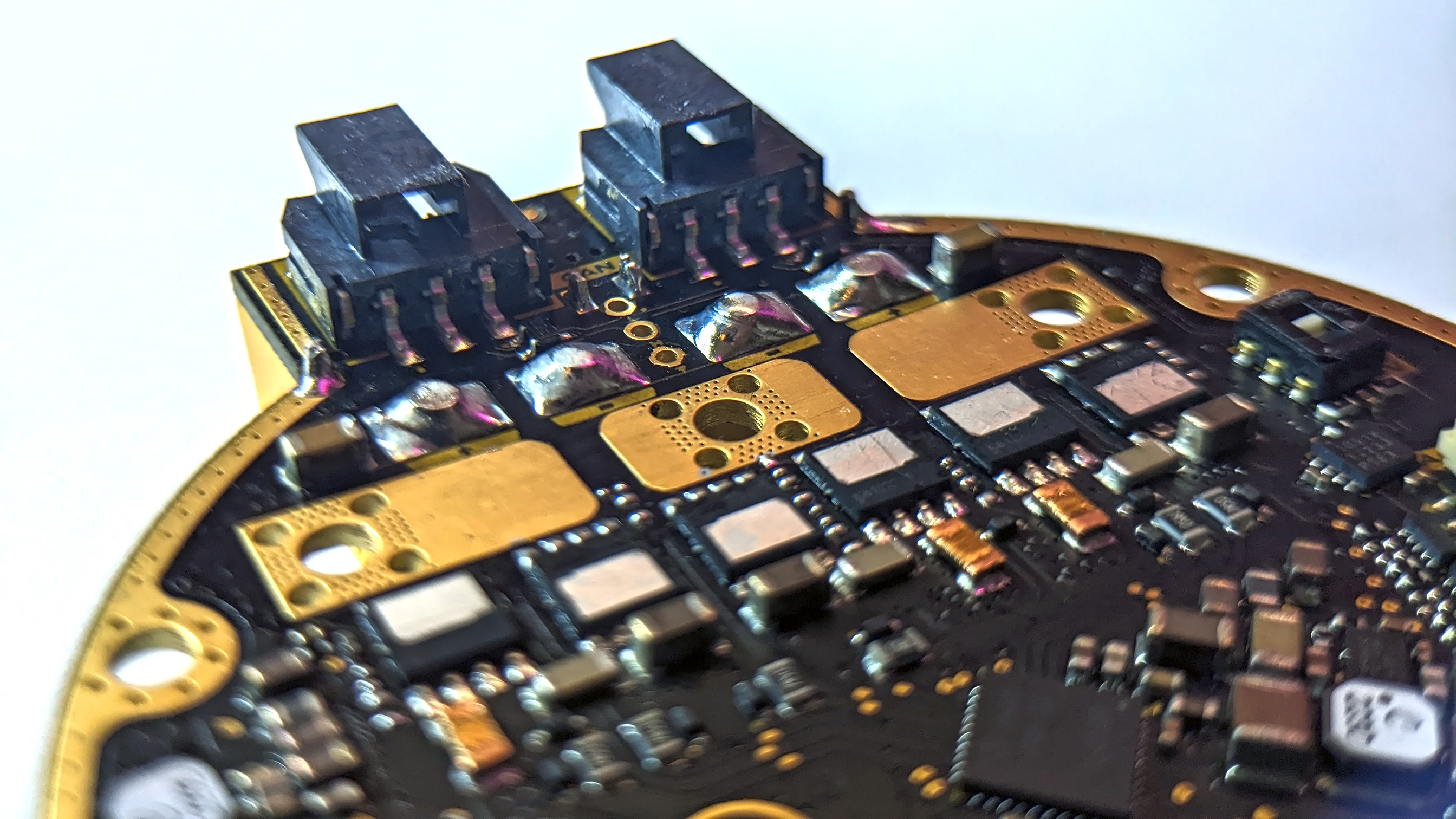
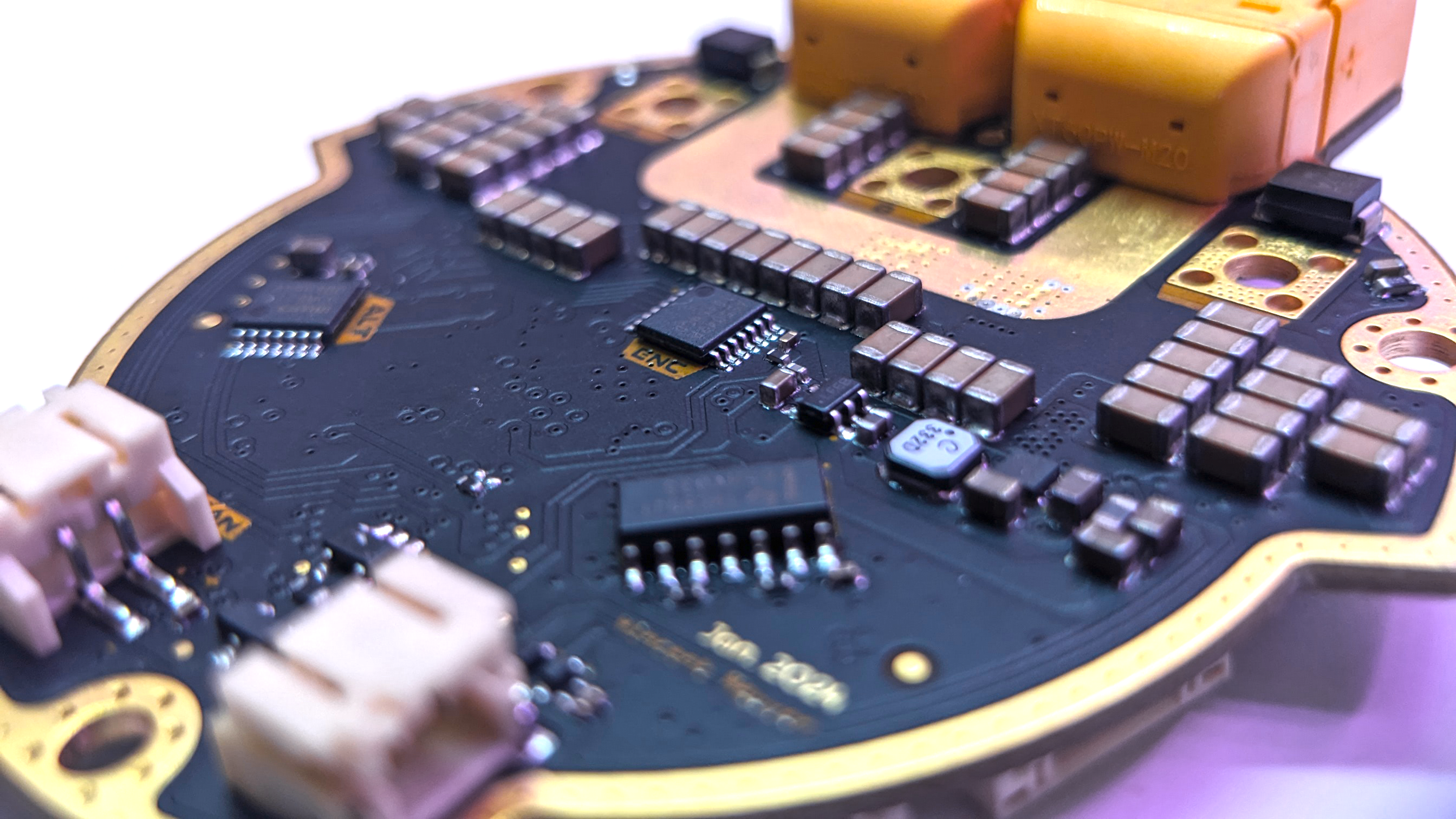
| Qty | Value | Footprint | References |
|---|---|---|---|
| 50 | 4u7 X7R 100V | 0_capacitor_smd:C_1206_3216_DensityHigh | C19, C21, C31, C32, C33, C34, C35, C36, C39, C40, C41, C42, C43, C44, C46, C47 +34 |
| 26 | 100n X7R 50V | 0_capacitor_smd:C_0402_1005_DensityHigh | C10, C11, C101, C102, C103, C104, C105, C107, C108, C109, C111, C112, C113, C114, C115, C125 +10 |
| 21 | mousebites_single_0.7mm | 0_mousebites:mousebites_single_0.7mm | MB1, MB2, MB3, MB4, MB10, MB11, MB12, MB13, MB14, MB15, MB16, MB17, MB18, MB19, MB20, MB21 +5 |
| 15 | 3n3 X7R 100V | 0_capacitor_smd:C_0402_1005_DensityHigh | C116, C117, C118, C119, C120, C121, C122, C123, C124, C133, C134, C135, C136, C137, C138 |
| 15 | BAT41KFILM | 0_diode_smd:D_SOD-523 | D3, D4, D5, D6, D7, D8, D9, D10, D11, D14, D15, D19, D20, D21, D22 |
| 14 | 100R 1% 1/5W | 0_resistor_smd:R_0402_1005_DensityHigh | R22, R23, R25, R35, R36, R37, R38, R39, R40, R41, R42, R43, R48, R49 |
| 7 | 2k 1% | 0_resistor_smd:R_0402_1005_DensityHigh | R8, R9, R28, R44, R45, R46, R47 |
| 7 | 2u2 X7R 100V | 0_resistor_smd:R_0805_2012_DensityHigh | C15, C16, C17, C18, C20, C45, C52 |
| 7 | GND | 0_testpoint:TestPoint_Pad_D0.5mm | TP52, TP53, TP54, TP55, TP56, TP57, TP58 |
| 6 | 100k 1% | 0_resistor_smd:R_0402_1005_DensityHigh | R5, R19, R20, R21, R24, R29 |
| 6 | 5R 1% 0.4W | 0_resistor_smd:R_0603_1608_DensityHigh | R55, R56, R57, R58, R59, R60 |
| 6 | 7R5 1% 1/2W | 0_resistor_smd:R_0805_2012_DensityHigh | R10, R11, R13, R14, R16, R17 |
| 6 | Fiducial | 0_fiducials:Fiducial_1mm_Mask2mm | FM1, FM2, FM3, FM4, FM5, FM6 |
| 6 | TPW1R306PL,L1Q | 0_transistor_fet:2-5S1A | Q1, Q2, Q3, Q4, Q5, Q6 |
| 5 | 1u X7R 10V | 0_capacitor_smd:C_0402_1005_DensityHigh | C2, C6, C9, C24, C26 |
| 4 | 1k @ 100MHz | 0_resistor_smd:R_0805_2012_DensityHigh | FB1, FB2, FB3, FB4 |
| 4 | 4u7 X7R 100V | 0_capacitor_smd:C_1206_3216_DensityHighest | C89, C96, C98, C100 |
| 4 | G*** | kibuzzard-657F7953 | kibuzzard-657F7953, kibuzzard-657F7953, kibuzzard-657F7953, kibuzzard-657F7953 |
| 4 | G*** | kibuzzard-657F78ED | kibuzzard-657F78ED, kibuzzard-657F78ED, kibuzzard-657F78ED, kibuzzard-657F78ED |
| 3 | +3V3 | 0_testpoint:TestPoint_Pad_D0.5mm | TP48, TP49, TP50 |
| 3 | +VBAT | 0_testpoint:TestPoint_Pad_D0.5mm | TP39, TP40, TP41 |
| 3 | 0R | 0_resistor_smd:R_0603_1608_DensityHigh | R52, R53, R54 |
| 3 | 0R | 0_resistor_smd:R_0402_1005_DensityHigh | R4, R31, R32 |
| 3 | 0m5 1% 2W | 0_resistor_smd:HCS1206FTL500 | R12, R15, R18 |
| 3 | 100n X7R 100V | 0_capacitor_smd:C_1206_3216_DensityHighest | C95, C97, C99 |
| 3 | 10k 1% | 0_resistor_smd:R_0402_1005_DensityHigh | R7, R27, R33 |
| 3 | 1n X7R 1kV | 0_capacitor_smd:C_0603_1608_DensityHigh | C130, C131, C132 |
| 3 | 1n X7R 25V | 0_capacitor_smd:C_0402_1005_DensityHigh | C12, C13, C14 |
| 3 | 1u X7R 25V | 0_capacitor_smd:C_0603_1608_DensityHigh | C60, C88, C93 |
| 3 | 22R 1% | 0_resistor_smd:R_0402_1005_DensityHigh | R1, R2, R3 |
| 3 | 4u7 X7R 16V | 0_capacitor_smd:C_0603_1608_DensityHigh | C1, C84, C110 |
| 3 | M3 | 0_pad:MountingHole_3.2mm_M3_Pad_Via | H1, H2, H3 |
| 3 | PMV90ENER | 0_package_SOT_TO_SMD:SOT-23-3 | Q7, Q8, Q9 |
| 2 | +5V | 0_testpoint:TestPoint_Pad_D0.5mm | TP46, TP47 |
| 2 | 100n X7R 100V | 0_capacitor_smd:C_0603_1608_DensityHigh | C22, C92 |
| 2 | 10u X7R 25V | 0_capacitor_smd:C_0805_2012_DensityHighest | C56, C106 |
| 2 | 15u X7R 25V | 0_capacitor_smd:C_1210_3225_DensityHigh | C30, C38 |
| 2 | 220n X7S 100V | 0_capacitor_smd:C_0603_1608_DensityHigh | C23, C25 |
| 2 | 22u | 0_inductor_smd:L_Coilcraft_LPS4018 | L1, L2 |
| 2 | 22u X7R 10V | 0_capacitor_smd:C_0805_2012_DensityHighest | C37, C83 |
| 2 | 60R4 1% 1/4W | 0_resistor_smd:R_0603_1608_DensityHigh | R50, R51 |
| 2 | CDSOT23-SM712 | 0_package_SOT_TO_SMD:SOT95P230X110-3N | D23, D27 |
| 2 | Nano-Fit 1x03 | 0_connectors:1054301203 | J12, J13 |
| 2 | PESD2CANFD24V-UX | 0_package_SOT_TO_SMD:SOT95P230X117-3N | D24, D25 |
| 2 | PESD4USB3U-TBSX | 0_package_DFN_QFN:SOT1176D | D18, D26 |
| 2 | PESD4USB5B-TBSX | 0_package_DFN_QFN:SOT1176D | D16, D17 |
| 2 | S2B-PH-SM4-TB | 0_connectors:JST_PH_S2B-PH-SM4-TB_1x02-1MP_P2.00mm_Horizontal | J8, J9 |
| 2 | SMBJ51CD-M3/H | 0_diode_smd:DIOM4336X24N | D1, D2 |
| 1 | +12V | 0_testpoint:TestPoint_Pad_D0.5mm | TP45 |
| 1 | +A3V3 | 0_testpoint:TestPoint_Pad_D0.5mm | TP51 |
| 1 | 100n X7R 16V | 0_capacitor_smd:C_0402_1005_DensityHigh | C90 |
| 1 | 10R 1% | 0_resistor_smd:R_0603_1608_DensityHigh | R34 |
| 1 | 10n X7R 100V | 0_capacitor_smd:C_0402_1005_DensityHigh | C76 |
| 1 | 150R 1% 1/5W | 0_resistor_smd:R_0402_1005_DensityHigh | R26 |
| 1 | 1u X7R 6.3V | 0_capacitor_smd:C_0402_1005_DensityHigh | C94 |
| 1 | 2u2 | 0_inductor_smd:L_Coilcraft_LPS3314 | L3 |
| 1 | 47k 1% NTC | 0_resistor_smd:R_0402_1005_DensityHigh | TH1 |
| 1 | 47n X7R 100V | 0_capacitor_smd:C_0603_1608_DensityHigh | C91 |
| 1 | 4k7 1% | 0_resistor_smd:R_0402_1005_DensityHigh | R30 |
| 1 | 4n7 X7R 100V | 0_capacitor_smd:C_0402_1005_DensityHigh | C129 |
| 1 | 4u7 X5R 25V | 0_capacitor_smd:C_0402_1005_DensityHigh | C7 |
| 1 | 9k09 1% | 0_resistor_smd:R_0402_1005_DensityHigh | R6 |
| 1 | AS5047P | 0_package_SO:SOP-14_4.4x5mm_P0.65mm_H1.2mm | U7 |
| 1 | AS5048B | 0_package_SO:SOP-14_4.4x5mm_P0.65mm_H1.2mm | U8 |
| 1 | AUX1_A | 0_testpoint:TestPoint_Pad_D0.5mm | TP17 |
| 1 | AUX1_B | 0_testpoint:TestPoint_Pad_D0.5mm | TP18 |
| 1 | AUX1_C | 0_testpoint:TestPoint_Pad_D0.5mm | TP19 |
| 1 | AUX1_D | 0_testpoint:TestPoint_Pad_D0.5mm | TP20 |
| 1 | AUX1_E | 0_testpoint:TestPoint_Pad_D0.5mm | TP21 |
| 1 | AUX1_I2C_PULLUP | 0_testpoint:TestPoint_Pad_D0.5mm | TP22 |
| 1 | AUX2_A | 0_testpoint:TestPoint_Pad_D0.5mm | TP24 |
| 1 | AUX2_B | 0_testpoint:TestPoint_Pad_D0.5mm | TP25 |
| 1 | AUX2_C | 0_testpoint:TestPoint_Pad_D0.5mm | TP26 |
| 1 | AUX2_D | 0_testpoint:TestPoint_Pad_D0.5mm | TP27 |
| 1 | AUX2_I2C_PULLUP | 0_testpoint:TestPoint_Pad_D0.5mm | TP28 |
| 1 | CAS-220TA | 0_switch_button:CAS-220A_NDC-L | SW1 |
| 1 | DGD0216WT-7 | 0_package_SOT_TO_SMD:SOT-23-5 | U11 |
| 1 | DRV8353FS | 0_package_DFN_QFN:WQFN-40-1EP_6x6mm_P0.5mm_EP4.15x4.15mm_ThermalVias | U6 |
| 1 | DRV_CS | 0_testpoint:TestPoint_Pad_D0.5mm | TP7 |
| 1 | DRV_MISO | 0_testpoint:TestPoint_Pad_D0.5mm | TP5 |
The 317 most common of 414 parts.
EPFLXplore/XRE_LeggedRobot_HW
PCB designs for Xplore Research's robot dog project

nguyen-v/KiBot_Project_Test
A test project for the video tutorial using KDT_Hierarchical_KiBot template


EPFLXplore/Power_HW
KiCad design files for the power boards of the Xplore rover.


toby-lane-amodo/ARIA_SRB_FAFF_2_POC_CBs_1_FABLE_5_1
Electronics for FAFF 2 — a linear actuator with force feedback, built as an OEM-style module for soft-material characterisation. CBs1 is the proof-of-concept control board.


It measures 69.7 × 76.7 mm and has 6 copper layers, 1.66 mm thick.
414 parts, built around the AS5047P-ATSM, AS5048B-HTSP-500, DRV8353FSRTAR and GRJ31CZ72A475KE01L. The full list of its parts is on this page, with links to each part's symbol and footprint where PCBKit's library has them.
From the aidanbrzezinski/Prism-test repository on GitHub, at the commit this page was made from: the board is amulet_controller.kicad_pcb and its schematic Block Diagram.kicad_sch. PCBKit opens the board in the browser, with nothing to install.
Its repository states no licence, so its author keeps all rights: ask aidanbrzezinski before reusing the design.