4 layers100 × 100 mm
PA Power V1
RADARC/Modular-PA-Controller
Controller for High Power RF Power Amplifiers based Raspberry Pi Pico
116 parts
 RADARC/Modular-PA-Controller
Controller for High Power RF Power Amplifiers based Raspberry Pi Pico
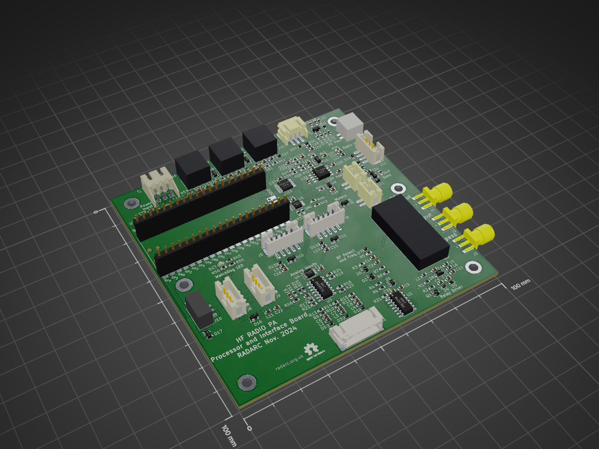
HF PA Radio Interface is an open-source printed circuit board by RADARC, from the RADARC/Modular-PA-Controller repository on GitHub. It is a 2-layer board of 100 × 100 mm with 187 parts on 124 nets, routed with 1,303 tracks and 260 vias.
It is built around the 74LVC1G17Z, 74AHCT125D and TLV9364ID, with the ADS1015IDGS, MCP4728-E/UN and 74LVC74AD among its other parts. Its parts include 56 resistors, 43 capacitors, 30 diodes, 18 connectors and 18 inductors. It belongs with the radio and wireless and audio and music boards and the RP2040 boards of this library.


Controller for High Power RF Power Amplifiers based Raspberry Pi Pico
Reading and District Amateur Radio Club(RADARC) are working together on a number of collaborative construction projects. This one is to design and build a Modular PA controller for High Power (1kW plus) semiconductor Power amplifiers. This prototype implementation is targetted on the High Power HF PA Modules from W6PQL :
The Modular PA Controller Is built around four PCB assemblies:
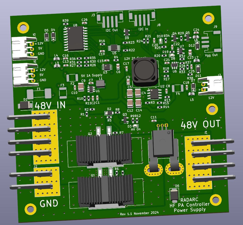
This board manages the high DC voltage (up to 72V) part of the PA controller. It provides switching of the DC supply up to 50A, also current monitoring and Voltage monitoring. The DC supply switching uses a watchdog an requires the processor to signal the switch every 500uS to keep the power on. It derives two lower voltage power supplies at 12V 2A and 5V 1A. The 3.3V logic supply for th PA controller is provided by the regulator on the Pi Pico on the processor board.To control the Vgg Bias to the Power Amplifier Modules the board provides either a switched 12V supply to a regulator on the Power Amplifier Board, and also a variable voltage software controlled DC output. All control and monitoring is via I2C control from the Processor Board.
This board contains the Raspberry Pi Pico microcontroller module. The module alo provides the 3.3V logic supply and the USB interface. Pi Pico modules with Bluetooth and Wi-fi may be used, also the higher performance RP2350 version.
The board has two I2C buses. The internal bus connects to the on board ADC and DAC devices. The external I2C bus connects to the Power Supply and Control board(s), the Relay Driver board(s), LM75 temperature sensors, I2C OLED display, etc.
The board has an input TX/RX relay to bypass the Power Amplifier Modules as required.
| Qty | Value | Footprint | References |
|---|---|---|---|
| 29 | 10k | Resistor_SMD:R_0603_1608Metric | R2, R10, R11, R12, R13, R14, R15, R16, R17, R18, R19, R20, R21, R22, R23, R24 +13 |
| 18 | 10n | Capacitor_SMD:C_0603_1608Metric | C3, C4, C5, C6, C7, C10, C19, C23, C35, C36, C37, C38, C39, C40, C41, C42 +2 |
| 18 | L_Ferrite | Inductor_SMD:L_0603_1608Metric | L1, L2, L3, L4, L5, L6, L7, L10, L11, L12, L13, L14, L15, L16, L17, L18 +2 |
| 16 | 100n | Capacitor_SMD:C_0603_1608Metric | C11, C12, C13, C14, C15, C16, C18, C20, C22, C24, C26, C29, C30, C31, C33, C43 |
| 9 | SMF4L5.0A | Diode_SMD:D_SOD-523 | D1, D3, D6, D7, D13, D14, D15, D24, D28 |
| 7 | SMF4L12A | Diode_SMD:D_SOD-523 | D4, D9, D20, D22, D25, D26, D27 |
| 7 | SP0503BAHT | Package_TO_SOT_SMD:SOT-143 | D10, D11, D16, D17, D19, D29, D30 |
| 6 | 1k | Resistor_SMD:R_0603_1608Metric | R3, R4, R26, R27, R35, R45 |
| 6 | MountingHole_Pad | MountingHole:MountingHole_3.2mm_M3_DIN965_Pad | H1, H2, H3, H4, H5, H6 |
| 5 | 3k3 | Resistor_SMD:R_0603_1608Metric | R41, R42, R46, R53, R54 |
| 5 | 4k7 | Resistor_SMD:R_0603_1608Metric | R1, R31, R33, R55, R56 |
| 4 | 0R | Resistor_SMD:R_0603_1608Metric | R36, R48, R50, R52 |
| 4 | NF | Resistor_SMD:R_0603_1608Metric | R37, R47, R49, R51 |
| 3 | 10uF | Capacitor_SMD:C_0603_1608Metric | C28, C32, C34 |
| 3 | Conn_01x04 | HF_PA:KF2510-4AW_3+1P | J16, J17, J18 |
| 3 | Conn_01x04 | Connector_JST:JST_PH_B4B-PH-SM4-TB_1x04-1MP_P2.00mm_Vertical | J8, J9, J11 |
| 3 | Conn_Coaxial | HF_PA:SMA_Samtec_SMA-J-P-X-ST-EM1_EdgeMount | J2, J3, J4 |
| 2 | 10u | Capacitor_SMD:C_0805_2012Metric | C17, C21 |
| 2 | 1nF | Capacitor_SMD:C_0603_1608Metric | C1, C2 |
| 2 | 1uF | Capacitor_SMD:C_0603_1608Metric | C25, C27 |
| 2 | 74LVC1G17 | Package_TO_SOT_SMD:SOT-353_SC-70-5 | U1, U9 |
| 2 | BAT54SW | Package_TO_SOT_SMD:SOT-323_SC-70 | D2, D5 |
| 2 | Conn_01x02 | Connector_JST:JST_PH_B2B-PH-SM4-TB_1x02-1MP_P2.00mm_Vertical | J12, J13 |
| 2 | Conn_01x05 | Connector_JST:JST_PH_B5B-PH-SM4-TB_1x05-1MP_P2.00mm_Vertical | J5, J6 |
| 1 | 1N5400 | Diode_SMD:D_SOD-123 | D8 |
| 1 | 220 | Resistor_SMD:R_0603_1608Metric | R5 |
| 1 | 2N7002 | Package_TO_SOT_SMD:SOT-23 | Q2 |
| 1 | 30k | Resistor_SMD:R_0603_1608Metric | R34 |
| 1 | 470 | Resistor_SMD:R_0603_1608Metric | R6 |
| 1 | 74AHCT125 | Package_SO:TSSOP-14_4.4x5mm_P0.65mm | U10 |
| 1 | 74LVC74 | Package_SO:SOIC-14_3.9x8.7mm_P1.27mm | U2 |
| 1 | ADS1015IDGS | Package_SO:TSSOP-10_3x3mm_P0.5mm | U4 |
| 1 | AP2204K-ADJ | Package_TO_SOT_SMD:SOT-23-5 | U7 |
| 1 | BC848W | Package_TO_SOT_SMD:SOT-323_SC-70 | Q1 |
| 1 | Conn_01x02 | Connector_JST:JST_PH_S2B-PH-SM4-TB_1x02-1MP_P2.00mm_Horizontal | J14 |
| 1 | Conn_01x03 | Connector_JST:JST_PH_S3B-PH-SM4-TB_1x03-1MP_P2.00mm_Horizontal | J15 |
| 1 | Conn_01x03 | Connector_JST:JST_PH_B3B-PH-SM4-TB_1x03-1MP_P2.00mm_Vertical | J10 |
| 1 | Conn_01x04 | Connector_JST:JST_XH_S3B-XH-A_1x03_P2.50mm_Horizontal | J7 |
| 1 | Conn_01x06 | Connector_JST:JST_PH_S6B-PH-SM4-TB_1x06-1MP_P2.00mm_Horizontal | J1 |
| 1 | DMG2305UX | Package_TO_SOT_SMD:SOT-23 | Q3 |
| 1 | D_Small | Diode_SMD:D_SOD-323 | D21 |
| 1 | ESD131-B1-W0201 | Diode_SMD:D_SOD-523 | D18 |
| 1 | G2RL-1-E | Relay_THT:Relay_SPDT_Omron_G2RL-1-E | K1 |
| 1 | LED Green | LED_SMD:LED_0603_1608Metric | D23 |
| 1 | LTC1044 | Package_SO:SOIC-8_5.23x5.23mm_P1.27mm | U8 |
| 1 | Logo_Open_Hardware_Small | Symbol:OSHW-Logo2_7.3x6mm_SilkScreen | SYM1 |
| 1 | MCP4728 | Package_SO:MSOP-10_3x3mm_P0.5mm | U6 |
| 1 | RaspberryPi_Pico | HF_PA:RPi_Pico_SMD_TH | A1 |
| 1 | SMF4L12.0A | Diode_SMD:D_SOD-523 | D12 |
| 1 | TLV9361 | Package_TO_SOT_SMD:SOT-23-5 | U5 |
| 1 | TLV9364 | Package_SO:SOIC-14_3.9x8.7mm_P1.27mm | U3 |
RADARC/Modular-PA-Controller
Controller for High Power RF Power Amplifiers based Raspberry Pi Pico

loozhengyuan/MitsubishiSC
Smart controller for Mitsubishi Electric HVAC systems.

M0LTE/pi-transceiver
An attempt to build a complete ham radio transceiver around a Raspberry Pi

z2amiller/pedalfx
Replaces the Panasonic MN3102 (clock generator for MN3204/05/07/08/09 BBDs) with a CD4047B plus four passives. Two ways to use it:


souhaib250/SENS-CO-Wearable-Gas-Sensor
Design, simulation and PCB implementation of an embedded wireless acquisition node for a wearable WS2 gas sensor.

mlanagan/RemoteHF
Remote HF PCB and Node Red Website for WFView, SteppIRAntenna and Yeasu Rotator

It measures 100 × 100 mm and has 2 copper layers, 1.6 mm thick.
187 parts, built around the 74LVC1G17Z, 74AHCT125D, TLV9364ID and ADS1015IDGS. The full list of its parts is on this page, with links to each part's symbol and footprint where PCBKit's library has them.
From the RADARC/Modular-PA-Controller repository on GitHub, at the commit this page was made from: the board is Kicad/HF PA Radio Interface/HF PA Radio Interface.kicad_pcb and its schematic Kicad/HF PA Radio Interface/HF PA Radio Interface.kicad_sch. PCBKit opens the board in the browser, with nothing to install.
Its repository states no licence, so its author keeps all rights: ask RADARC before reusing the design.