Remote HF antenna switch: 3 radios x 4 antennas (path to 8), outdoor relay unit with a hardware safety chain, controlled over Cat6 from a shack interface. KiCad 10, open hardware, designed together with an AI.
Rf board is an open-source printed circuit board by PE1RGU, from the PE1RGU/hf-antenna-switch repository on GitHub, published under the CERN-OHL-S-2.0 licence. It is a 6-layer board of 268 × 230 mm with 357 parts on 242 nets, routed with 4,260 tracks and 4,208 vias.
It is built around the PCA9539PW, LM2901 and LP2985-33DBV, with the BSS138BK, 1N4148W and RTD14012F among its other parts. Its parts include 108 resistors, 55 capacitors, 54 diodes, 51 transistors and 43 switches. It belongs with the radio and wireless and home automation and IoT boards and the ESP32 and RISC-V boards of this library.
A remote antenna switch for an HF amateur radio station: 3 radios, 4 antennas, one Cat6 cable, and the safety rules in hardware.Designed by a radio amateur together with an AI assistant, and documented decision by decision.
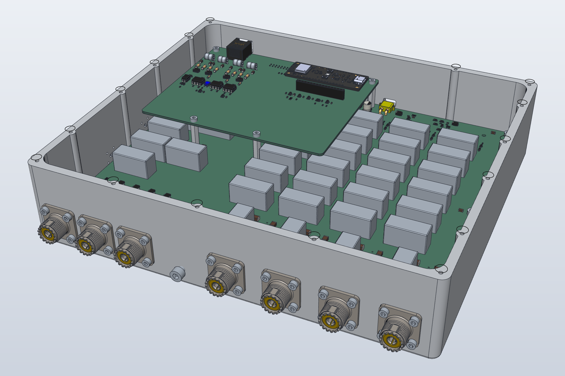
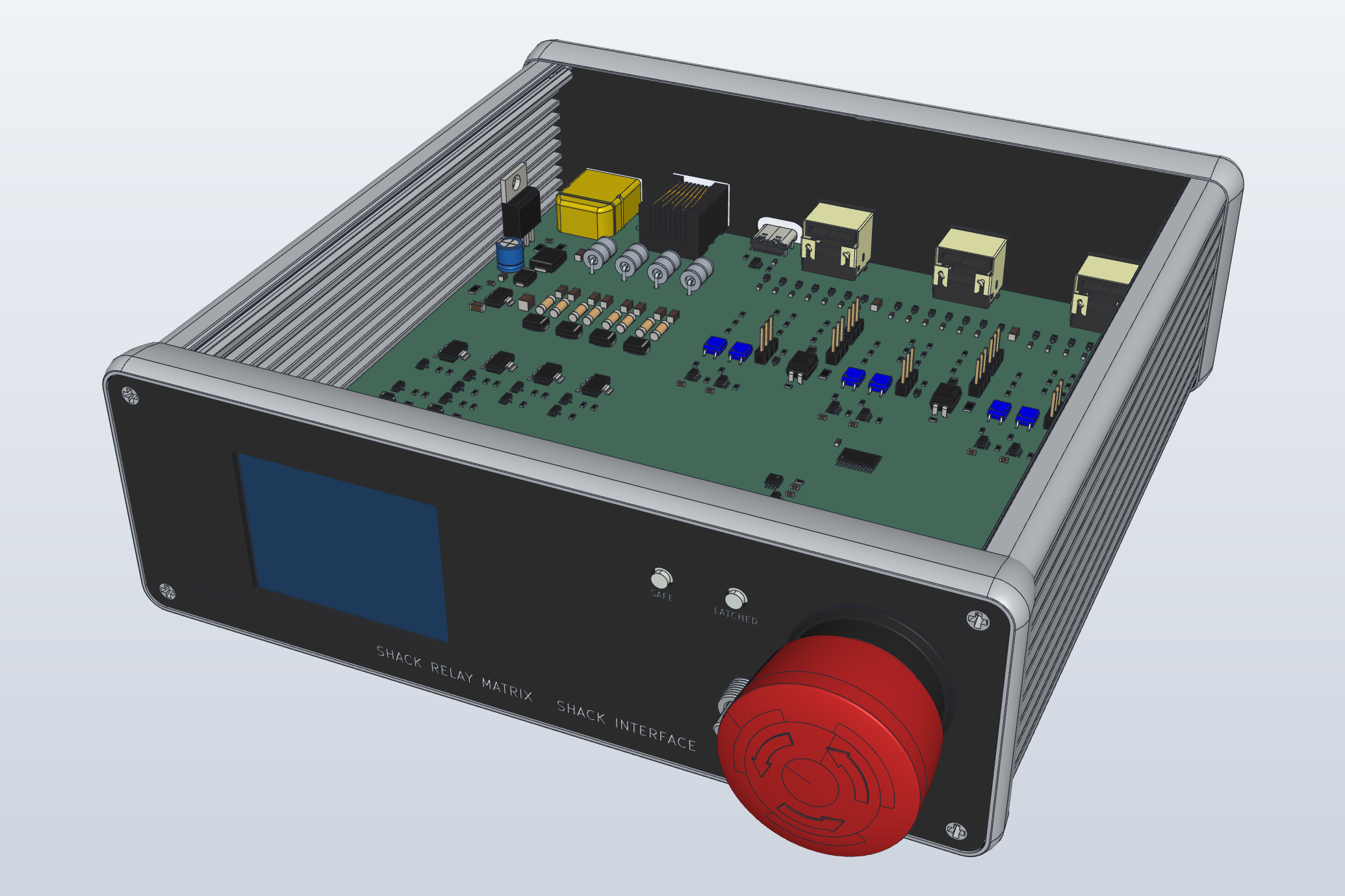
Left: the outdoor unit, lid removed. Right: the shack interface, cover removed. CAD views of the current design, not photos.
The relay unit sits outdoors, close to the antennas, in a milled aluminium case.
A small interface box in the shack controls it over one Cat6 cable.
A computer sends the commands over USB.
If anything goes wrong (a cable break, a box fault, a press on the KILL switch), every radio is inhibited and every relay is released, without help from the firmware.
Status: design phase. Schematics, layouts and the case are drawn and checked by scripts. No board is built yet, and nothing here is tested on the bench. The shack interface firmware runs in an emulator on the computer.
In numbers
Radios
3, each with its own transmit antenna and receive antenna
Antennas
4 per unit; a second unit adds 4 more
Frequency range
1.8 to 54 MHz
Power
100 W, SWR up to 3:1
Relays
37 × TE RT1, one type everywhere
RF board
6 layers, 50 Ω coplanar lines
Link to the shack
One Cat6 cable, four opto-isolated current loops
Outdoor case
Milled aluminium tray, 288 × 250 × 66 mm
Shack case
Hammond 1455T1601 extrusion, PCB end plates
Controllers
ESP32-C3 in the box and in the shack
Why this project may interest you
Safety in hardware, not only in software.
A receive-only antenna (such as a loop with a preamplifier) never sees transmit power.
No relay switches while RF is present.
The firmware may ask for a state. The hardware decides whether that state is allowed.
Designed with an AI, in the open.
This is an experiment in how a person and an AI assistant (Claude, by Anthropic) design hardware together.
I set the goals and took the decisions. The AI did much of the research, the calculations and the scripts.
The design log records every decision, who took it, and why. Rejected options stay in it too.
See docs/how-this-was-made.md for the method and its limits.
Everything comes from scripts.
Schematics, footprints, board placement, routing, end plates, the 3D fit checks and these renders are all generated by Python scripts.
A change is repeatable, and two revisions can be compared.
The logic is checked with truth tables against the real netlists.
tools/README.md lists every script and how to run it.
What it does
Connects each of 3 radios to a transmit antenna and, separately, to a receive antenna.
Keeps receive-only antennas away from transmit power.
Changes relays only when no RF is present (TX inhibit and handshake per radio).
Stops all transmission and releases all relays on any fault, cable break or KILL switch.
Grounds antennas that are not in use, through a static bleed.
Feeds an active receive antenna through a switched bias-T.
Is controlled from a computer over USB through the shack interface.
System overview
mermaid
flowchart LR
  subgraph SHACK["Shack"]
    PC["Computer"]
    SI["Shack interface<br/>SAFE latch, TX permits,<br/>radio ports R1 to R3"]
    R1["R1 FT-710"]
    R2["R2"]
    R3["R3"]
  end
  subgraph BOX["Outdoor unit, milled aluminium case"]
    CB["Controller board<br/>ESP32-C3, safety gate, watchdog"]
    RF["RF board<br/>3 radios x 4 antennas<br/>37 x TE RT1 relays"]
  end
  subgraph ANT["Antennas"]
    A1["A1 G5RV"]
    A2["A2 RX loop"]
    A34["A3, A4 spare"]
  end
  U2["Unit 2, optional<br/>+4 antennas"]
  PC -- USB --> SI
  SI == "Cat6: 4 opto current loops" ==> CB
  CB -- I2C --> RF
  R1 -- coax --> RF
  R2 -- coax --> RF
  R3 -- coax --> RF
The dotted lines from the radios are the TUNER and LINEAR jacks (TX inhibit, PTT sense).
More detail, and the reason for each choice, is in docs/architecture.md.
The outdoor unit
The RF board carries the relay matrix: per radio a changeover relay, a transmit row and a receive row; per antenna a ground relay, a static bleed, an RF detector and an optional bias-T.
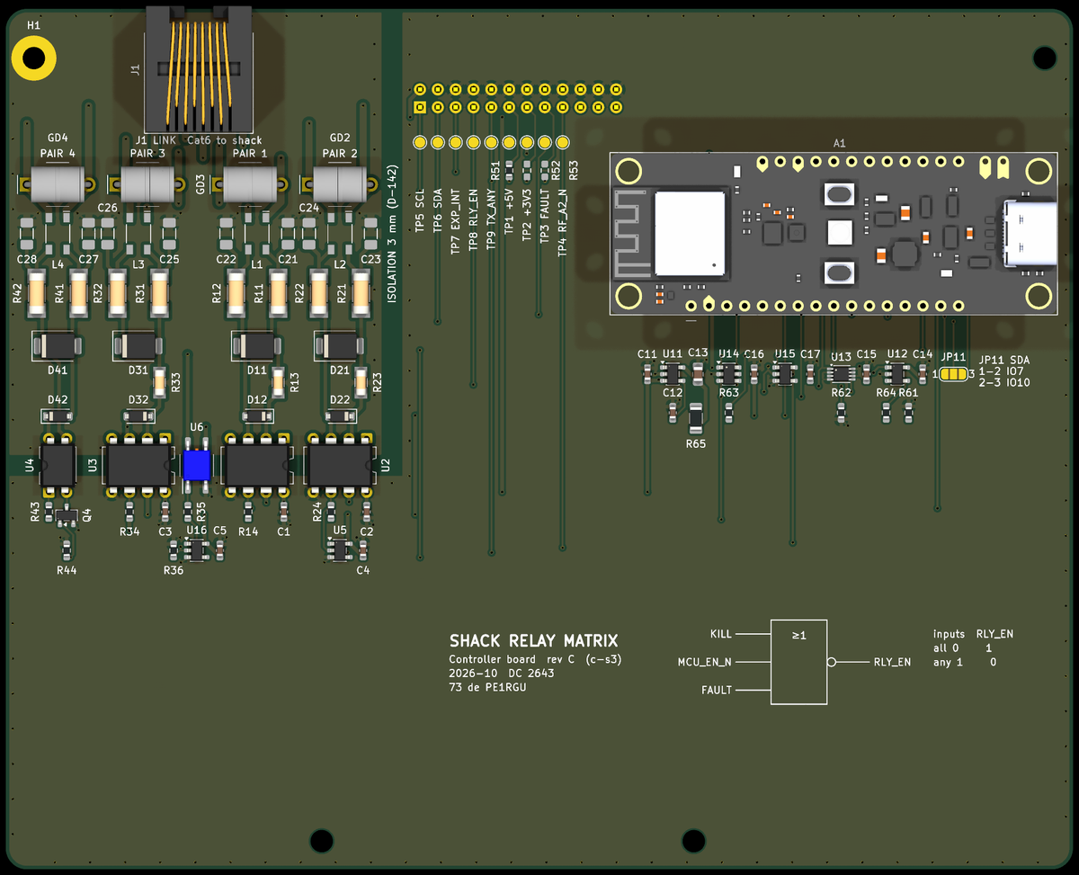
The controller board sits on standoffs above it.
Controller board (KiCad render). Left: the Cat6 link with the opto current loops and a 3 mm isolation gap. Right: the ESP32-C3 DevKit. The NOR gate on the silkscreen is the relay enable: RLY_EN = NOR(KILL, MCU_EN_N, FAULT).
The shack interface
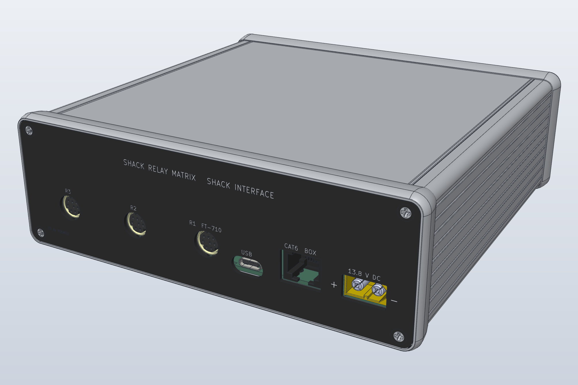
The shack interface powers the four current loops, holds the SAFE latch and the transmit permits, and connects to the three radios.
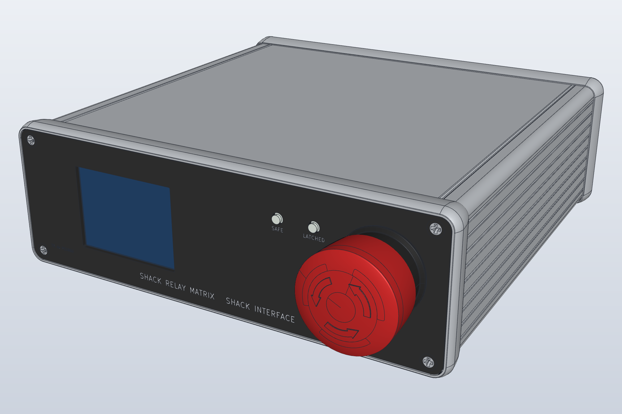
At the front: a 2 inch colour display, the SAFE and LATCHED LEDs, RESET and the KILL switch.
At the rear: 13.8 V DC, Cat6 to the outdoor unit, USB and the three radio ports.
Front and rear of the shack interface (SolidCraft views).
Safety chain
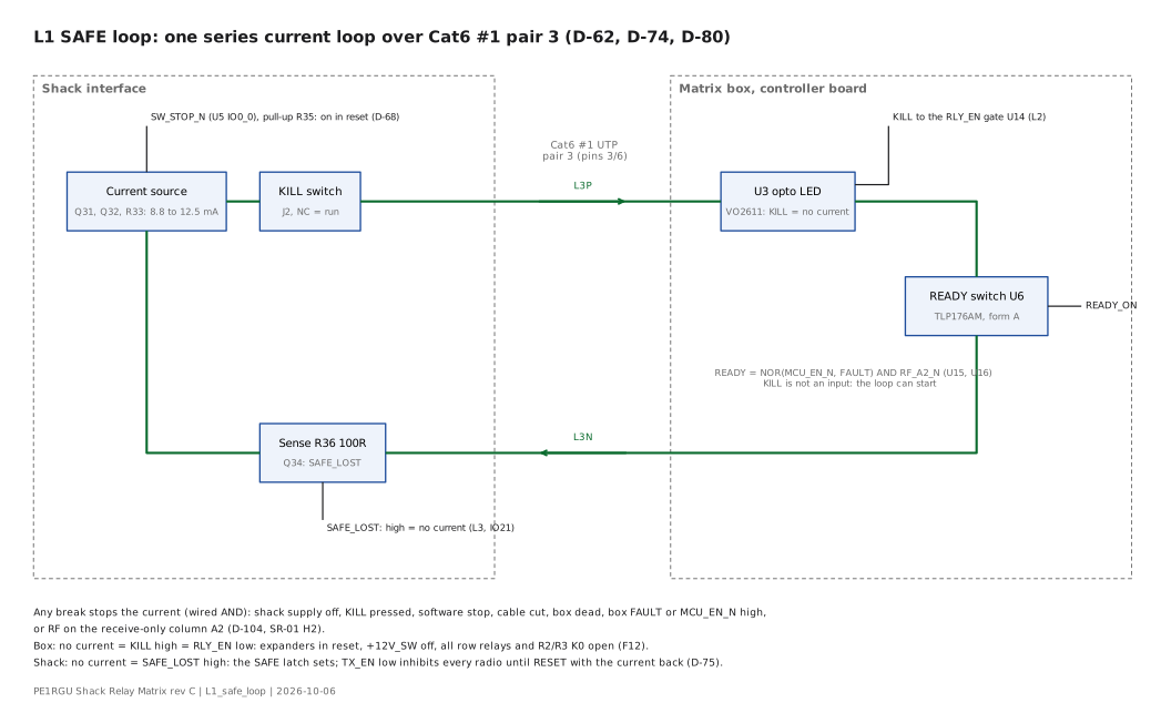
The SAFE loop is one series current loop from the shack to the box and back.
Any break stops the current: KILL switch, cable cut, box fault, or loss of power.
All radios are then inhibited and all relays released, in hardware, without help from the firmware.
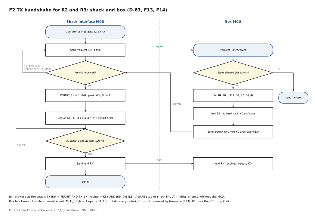
Radios R2 and R3 transmit only after a handshake with the box: request, state check, relay set, read-back, permit.
The firmware is written in Rust and runs on an ESP32-C3 in the box and in the shack.
No board exists yet, so the firmware is developed in an emulator.
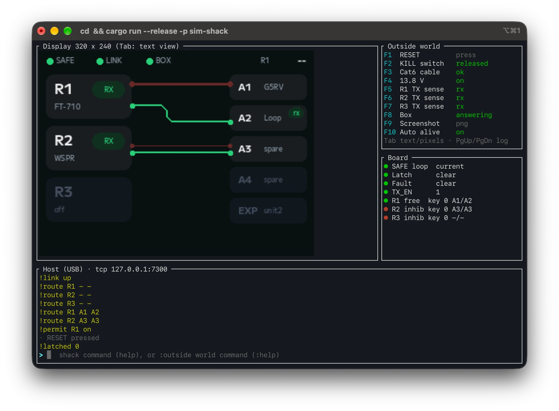
The emulator runs the same firmware logic that goes into the ESP32-C3, against models of the parts on the board: the I/O expander, the supervisors and latches, the SAFE loop, the radio ports, the data link to the box and the display.
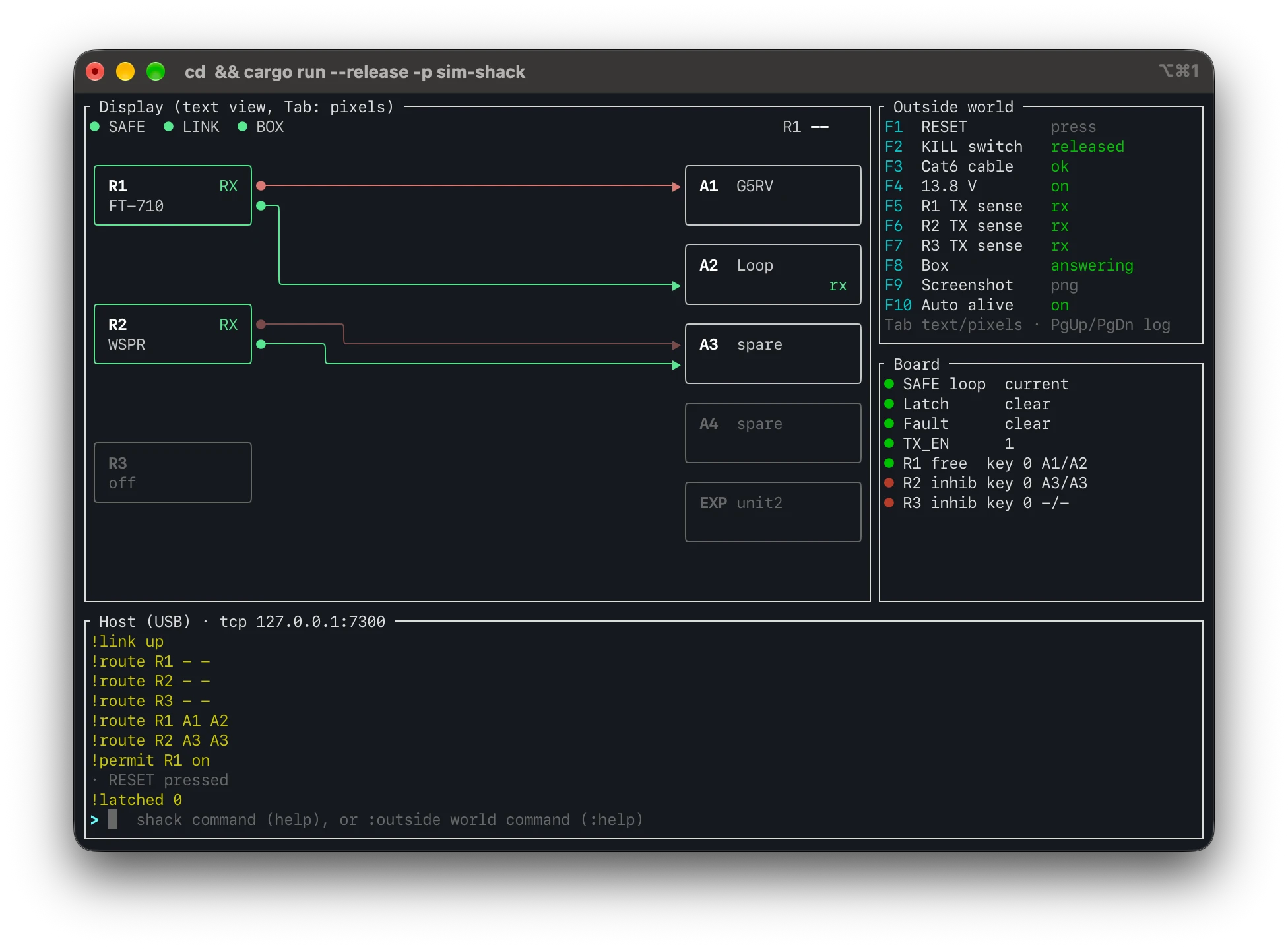
The emulated shack interface in a terminal. Left: pixel view, the 2 inch display exactly as the firmware draws it. Right: text view, for terminals without images. R1 transmits on A1 and receives on the loop A2; R2 uses A3.
In the emulator you can:
see the shack display as the firmware draws it (page B: radios, antennas and their routes; page C: one card per radio; the Safe stop screen with its cause and the steps to recover),
press RESET and KILL, cut the cable, switch the supply, and let a radio transmit, with function keys,
type the same commands that a station program sends over USB, or connect a program over TCP,
stop it and start it again: the routes, names and page come back, as on the real unit; a transmission never does.
It runs in a terminal on macOS, Linux and Windows:
bash
cd firmware
bash
cargo run --release -p sim-shack
firmware/README.md explains how the emulator works, every key and command, and a first session step by step.
To read or change the code, start with the firmware guide, written for hobby programmers.
Where it stands
Part
State
Requirements and architecture
Requirements in draft, architecture rev C
Schematics, all boards
Generated, ERC clean, logic checked by script
RF board layout
Placed and routed, DRC clean
Controller board layout
Placed and routed, DRC clean
Shack interface layout
Placed and routed, DRC clean; end plates drawn
Cases
Outdoor tray and shack end plates drawn; 3D fit checked
Firmware, shack interface
Runs in the emulator: permits, handshake, host protocol, display, stored settings; tested against the hardware logic
Firmware, box controller
Not started; a scripted box stands in for it in the emulator
docs/                       requirements, architecture, design, test, images
hardware/unit/              outdoor unit: RF board, controller board, case, verification scripts
hardware/shack-interface/   shack interface board, end plates, case fit and renders
hardware/docs/diagrams/     logic, timing and flow diagrams
firmware/                   Rust firmware and the emulator (see firmware/README.md)
tools/README.md             where each generator and verification script is, and how to run it
Datasheets/                 datasheet register (the PDFs are not in the repository)
archive/                    earlier revisions (card cage and backplane, rev A/B)
Tools
KiCad 10, with the board layouts generated by Python scripts
Rust for the firmware and the emulator (esp-hal, embedded-graphics, ratatui)
Python 3 for the generators, the router and the verification scripts
cadquery and SolidCraft for the cases, the 3D fit checks and the renders
JLCPCB for the PCBs
Licence
Hardware design files and documentation: CERN Open Hardware Licence v2, Strongly Reciprocal (CERN-OHL-S-2.0). See LICENSE.
Python scripts (generators, verification) and the firmware (Rust): MIT. See LICENSE-MIT.
The display fonts compiled into the firmware are M+ FONTS (through the mplusfonts crate), under the SIL Open Font License 1.1.
Vendor 3D models and libraries (SnapEDA, SamacSys, Ultra Librarian, Amass, Amphenol) are not in the repository. See hardware/THIRD-PARTY.md for where to get them.
Remote HF antenna switch: 3 radios x 4 antennas (path to 8), outdoor relay unit with a hardware safety chain, controlled over Cat6 from a shack interface. KiCad 10, open hardware, designed together with an AI.
Remote HF antenna switch: 3 radios x 4 antennas (path to 8), outdoor relay unit with a hardware safety chain, controlled over Cat6 from a shack interface. KiCad 10, open hardware, designed together with an AI.
Remote HF antenna switch: 3 radios x 4 antennas (path to 8), outdoor relay unit with a hardware safety chain, controlled over Cat6 from a shack interface. KiCad 10, open hardware, designed together with an AI.
Remote HF antenna switch: 3 radios x 4 antennas (path to 8), outdoor relay unit with a hardware safety chain, controlled over Cat6 from a shack interface. KiCad 10, open hardware, designed together with an AI.
Remote HF antenna switch: 3 radios x 4 antennas (path to 8), outdoor relay unit with a hardware safety chain, controlled over Cat6 from a shack interface. KiCad 10, open hardware, designed together with an AI.
Remote HF antenna switch: 3 radios x 4 antennas (path to 8), outdoor relay unit with a hardware safety chain, controlled over Cat6 from a shack interface. KiCad 10, open hardware, designed together with an AI.
It measures 268 × 230 mm and has 6 copper layers, 1.6 mm thick.
What parts does the Rf board use?
357 parts, built around the PCA9539PW, LM2901, LP2985-33DBV and BSS138BK. The full list of its parts is on this page, with links to each part's symbol and footprint where PCBKit's library has them.
Where can I download the Rf board KiCad files?
From the PE1RGU/hf-antenna-switch repository on GitHub, at the commit this page was made from: the board is hardware/unit/rf-board/rf-board.kicad_pcb and its schematic archive/2x1_as/2x1_as.kicad_sch. PCBKit opens the board in the browser, with nothing to install.
Can I use the Rf board design in my own project?
Its repository publishes it under the CERN-OHL-S-2.0 licence: you may reuse it on that licence's terms (keep the author's notice, and for a copyleft licence share your changes alike).