2 layers40.6 × 55.9 mm
MCF8316A Module
rich21044/Openmower-for-Landroid-WR141E
Taking the hardware developed as part of ClemensElfleins work on Openmower and adapting it to fit a 2019 Landroid WR141E.
21 parts8GPL-3.0

 shobhitsinha04/battlebot
2 lb combat robot with custom ESP32 PCB, ECE 445 UIUC
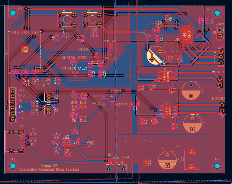
Battlebot is an open-source printed circuit board by shobhitsinha04, from the shobhitsinha04/battlebot repository on GitHub. It is a 2-layer board of 101.6 × 76.2 mm with 73 parts on 71 nets, routed with 427 tracks and 65 vias.
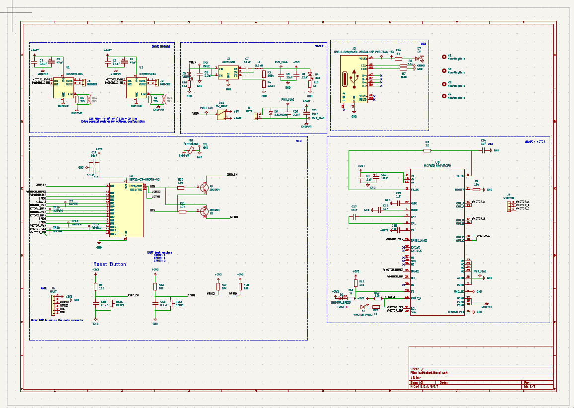
It is built around the ESP32-C3-WROOM-02-H4, DRV8871DDA and MCF8316A1VRGFR. Its parts include 24 resistors, 21 capacitors, 7 diodes, 6 connectors and 5 ICs. It belongs with the robots and motor control boards and the ESP32 and RISC-V boards of this library.


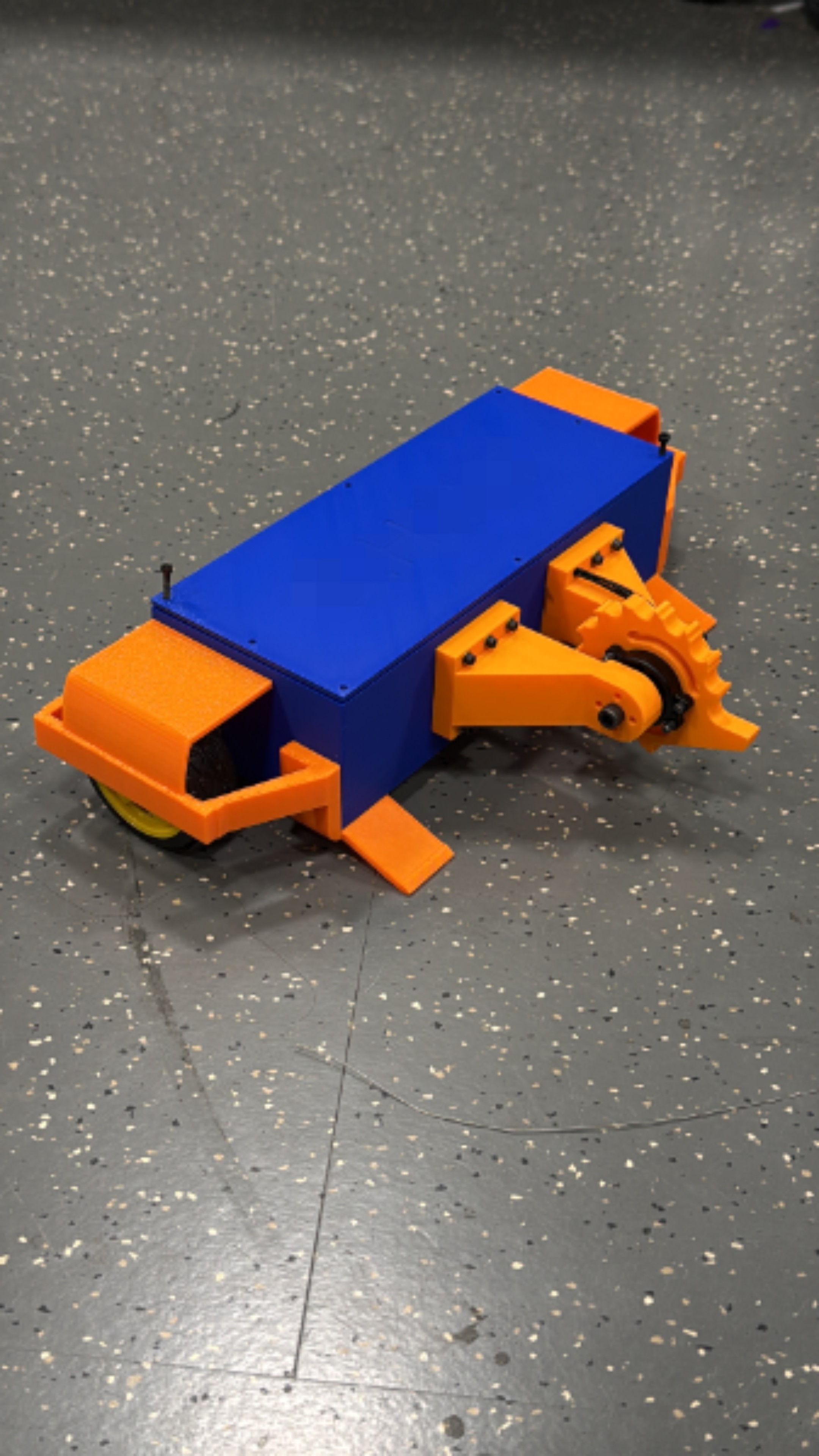
A 2 lb antweight combat robot built for ECE 445 (Senior Design) at the University of Illinois Urbana-Champaign, Spring 2026. It runs on a custom ESP32 control PCB, drives two wheels plus a brushless spinning weapon, and is controlled wirelessly from an Xbox controller.
| Requirement | Target | Measured |
|---|---|---|
| End-to-end wireless latency | under 100 ms | 75 ms |
| Command update rate | stable | 50 Hz |
| Wireless range | 15 ft line of sight | stable at 15 ft |
| Motor shutdown on signal loss | within 250 ms | within 250 ms (firmware watchdog) |
| Weight class | 2 lb antweight | met |
The PCB was designed in KiCad. Open hardware/battlebot.kicad_pro to view the schematic and layout.
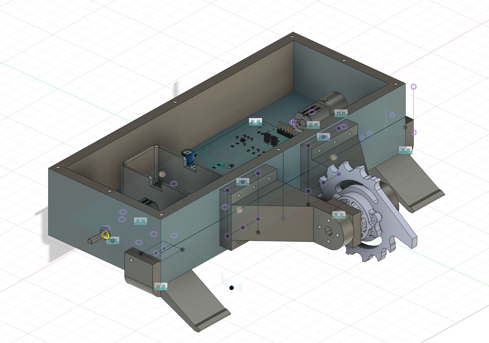
The chassis is a low, wide box with defined internal zones for the battery, PCB, drive motors and wiring, so the electrical team could integrate without redesigning the shell. Skids, wheel protectors and weapon arms are separate bolt-on parts so each could be revised and reprinted on its own. A failed weapon shaft coupler in April led to a redesigned wheel-to-shaft mount and brushless-specific motor arms.
assets/      Photos used in this README
hardware/    KiCad schematic, PCB layout, custom symbols and footprints
notebook/ Engineering lab notebooks for each team member, with build photos| Member | Focus |
|---|---|
| Abhinav Garg | Firmware, controller interface, motor control, system verification |
| Rahul Krishnamoorthy | PCB, power path, protection, electrical testing |
| Shobhit Sinha | Chassis, motor mounts, skids, wheels, weapon mounting, printed-part design |
Full dated engineering notes live in notebook/notebooks. Original repositories by Abhinav Garg are at ece445-pcb and ece445-lab-notebook.
| Qty | Value | Footprint | References |
|---|---|---|---|
| 9 | 10k | Resistor_SMD:R_0805_2012Metric | R5, R9, R10, R11, R17, R18, R20, R21, R22 |
| 6 | 0.1uF | Capacitor_SMD:C_0805_2012Metric | C1, C3, C7, C10, C12, C13 |
| 5 | 1k | Resistor_SMD:R_0805_2012Metric | R12, R13, R14, R15, R24 |
| 4 | 1uF | Capacitor_SMD:C_0805_2012Metric | C14, C15, C16, C18 |
| 4 | 32k | Resistor_SMD:R_0805_2012Metric | R1, R2, R19, R23 |
| 4 | MountingHole | MountingHole:MountingHole_2.2mm_M2 | H1, H2, H3, H4 |
| 3 | 5.1k | Resistor_SMD:R_0805_2012Metric | R6, R7, R16 |
| 2 | 10uF | Capacitor_THT:CP_Radial_D8.0mm_P5.00mm | C19, C21 |
| 2 | 2.2uF | Capacitor_SMD:C_0805_2012Metric | C8, C20 |
| 2 | 22uF | Capacitor_SMD:C_0805_2012Metric | C5, C6 |
| 2 | 2N3904 | Package_TO_SOT_THT:TO-92_Inline | Q1, Q2 |
| 2 | 47uF | Capacitor_THT:CP_Radial_D8.0mm_P5.00mm | C2, C4 |
| 2 | DRV8871DDA | Package_SO:Texas_HTSOP-8-1EP_3.9x4.9mm_P1.27mm_EP2.95x4.9mm_Mask2.4x3.1mm_ThermalVias | U1, U2 |
| 1 | .1uF | Capacitor_SMD:C_0805_2012Metric | C9 |
| 1 | 1.5SMCxxA | Diode_SMD:D_SMC | D6 |
| 1 | 100k | Resistor_SMD:R_0805_2012Metric | R3 |
| 1 | 10uF | Capacitor_SMD:C_0805_2012Metric | C11 |
| 1 | 22 | Resistor_SMD:R_0805_2012Metric | R8 |
| 1 | 22.1k | Resistor_SMD:R_0805_2012Metric | R4 |
| 1 | 3V3 | Capacitor_SMD:C_0805_2012Metric | D4 |
| 1 | 47nF | Capacitor_SMD:C_0805_2012Metric | C17 |
| 1 | 5.6uH | Inductor_SMD:L_0805_2012Metric | L1 |
| 1 | 5V | Capacitor_SMD:C_0805_2012Metric | D7 |
| 1 | BATT | Connector_PinHeader_2.54mm:PinHeader_1x02_P2.54mm_Vertical | J5 |
| 1 | DEBUG | Capacitor_SMD:C_0805_2012Metric | D3 |
| 1 | ESP32-C3-WROOM-02 | RF_Module:ESP32-C3-WROOM-02U | U4 |
| 1 | GPIO8 | Button_Switch_THT:SW_TH_Tactile_Omron_B3F-100x | RST2 |
| 1 | LMR51430 | Package_TO_SOT_SMD:SOT-23-6 | U3 |
| 1 | MCF8316A1VRGFR | local_footprints:RGF0040E-IPC_A | U5 |
| 1 | MOTOR1 | Connector_PinSocket_2.54mm:PinSocket_1x02_P2.54mm_Vertical | J1 |
| 1 | MOTOR2 | Connector_PinSocket_2.54mm:PinSocket_1x02_P2.54mm_Vertical | J2 |
| 1 | RESET | Button_Switch_THT:SW_TH_Tactile_Omron_B3F-100x | RST1 |
| 1 | SW_SPDT | Button_Switch_SMD:SW_SPDT_CK_JS102011SAQN | SW2 |
| 1 | UART | Connector_PinHeader_2.54mm:PinHeader_1x06_P2.54mm_Vertical | J6 |
| 1 | USB_C_Receptacle_USB2.0_16P | Connector_USB:USB_C_Receptacle_G-Switch_GT-USB-7010ASV | J3 |
| 1 | VMUX | Capacitor_SMD:C_0805_2012Metric | D5 |
| 1 | WMOTOR | Connector_PinHeader_2.54mm:PinHeader_1x03_P2.54mm_Vertical | J4 |
| 1 | WMOTOR_FAULT | Capacitor_SMD:C_0805_2012Metric | D1 |
| 1 | WMOTOR_SPEED | Capacitor_SMD:C_0805_2012Metric | D2 |
rich21044/Openmower-for-Landroid-WR141E
Taking the hardware developed as part of ClemensElfleins work on Openmower and adapting it to fit a 2019 Landroid WR141E.

williamthayer/DaisyBoards
A full repo of all the design files for each DaisyBoard


fwachsmuth/Filmkorn-Raw-Scanner
The Filmkorn Raw Scanner, turning 8mm and 16mm films into lossless 12-bit CinemaDNG


AlessioMorale/unav2_hardware
Initial test hardware for the future uNav board version

It measures 101.6 × 76.2 mm and has 2 copper layers, 1.6 mm thick.
73 parts, built around the ESP32-C3-WROOM-02-H4, DRV8871DDA and MCF8316A1VRGFR. The full list of its parts is on this page, with links to each part's symbol and footprint where PCBKit's library has them.
From the shobhitsinha04/battlebot repository on GitHub, at the commit this page was made from: the board is hardware/battlebot.kicad_pcb and its schematic hardware/battlebot.kicad_sch. PCBKit opens the board in the browser, with nothing to install.
Its repository states no licence, so its author keeps all rights: ask shobhitsinha04 before reusing the design.