
2 layers42.7 × 62 mm

 sbbxiii/The-Armadillo
The Armadillo: Custom Arduino-compatible ATmega328P stepper motor controller PCB with Trinamic TMC2209 silent driver and single-wire UART
ATmega TMC2209 Driver is an open-source printed circuit board by sbbxiii, from the sbbxiii/The-Armadillo repository on GitHub, published under the MIT licence. It is a 4-layer board of 60 × 60 mm with 52 parts on 58 nets, routed with 450 tracks and 55 vias.
It is built around the ATMEGA328P-AU, CH340K and TMC2209-LA, with the SS14 among its other parts. Its parts include 20 capacitors, 12 resistors, 8 connectors, 4 ICs and 3 diodes. It belongs with the robots and motor control and interfaces and adapters boards and the AVR (ATmega, ATtiny) boards of this library.





 [blocked]


The Armadillo is an open-source, Arduino-compatible motion control PCB designed from first principles in KiCad 10.0.1. It pairs the reliable Microchip ATmega328P 8-bit AVR microcontroller with the high-performance Trinamic TMC2209-LA silent bipolar stepper motor driver on a rugged $60.0\text{ mm} \times 60.0\text{ mm}$ 2-layer FR-4 board.
Featuring an onboard WCH CH340K USB-to-UART converter with automated DTR auto-reset, The Armadillo provides seamless plug-and-play programming directly through the Arduino IDE, PlatformIO, or AVR-GCC toolchains. Key features include silent stepper motion via StealthChop2™, sensorless homing via StallGuard4™, dynamic runtime current tuning over a single-wire PD_UART interface, and hardware RC-filtered sensor inputs.
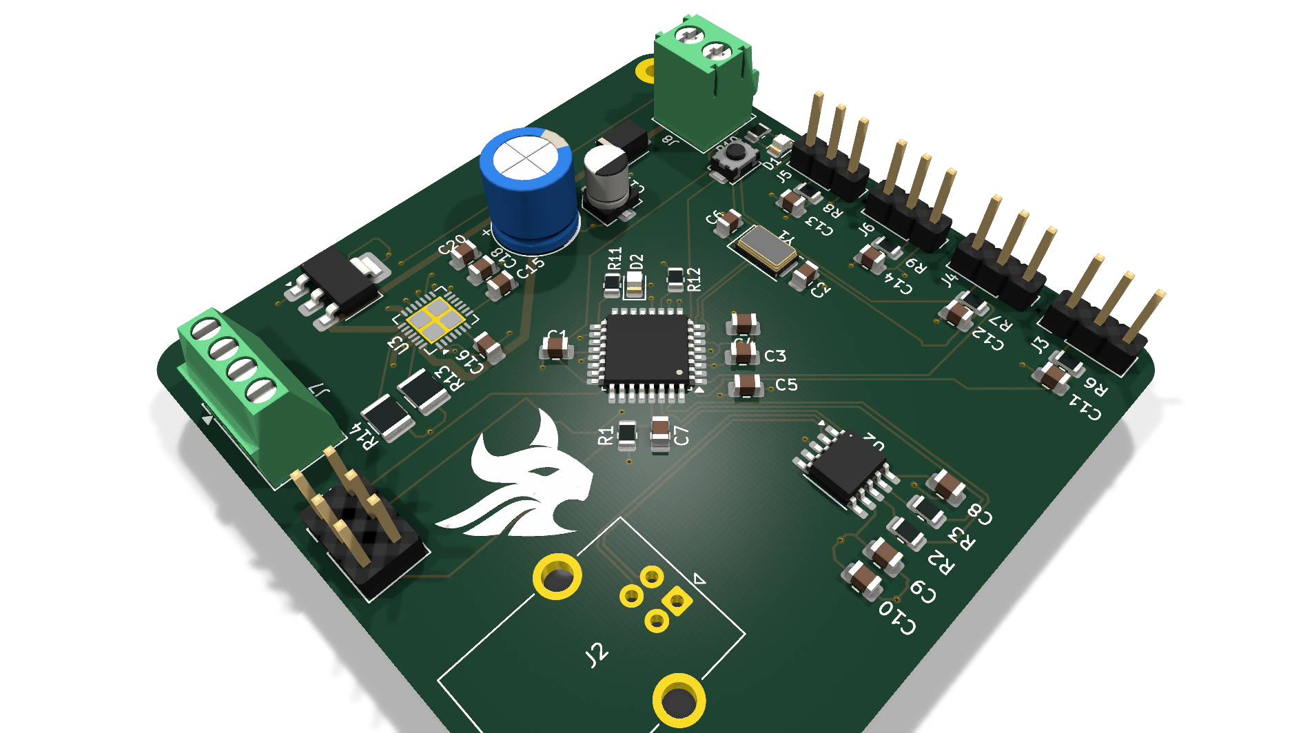
Figure 1: Raytraced 3D perspective view of The Armadillo motor controller board showing the ATmega328P core, TMC2209 driver, and screw terminal I/O.
| Top View (Silicon, Connectors & SMT Layout) | Bottom View (Solid Ground Return & Driver Thermal Vias) |
|---|---|
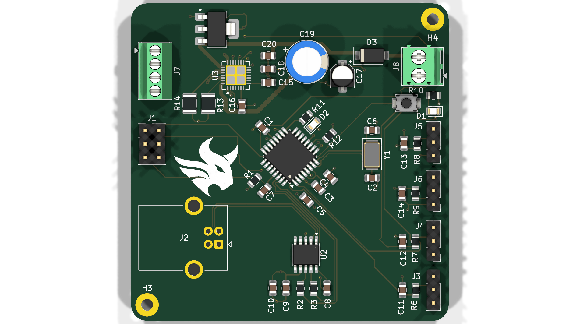 | 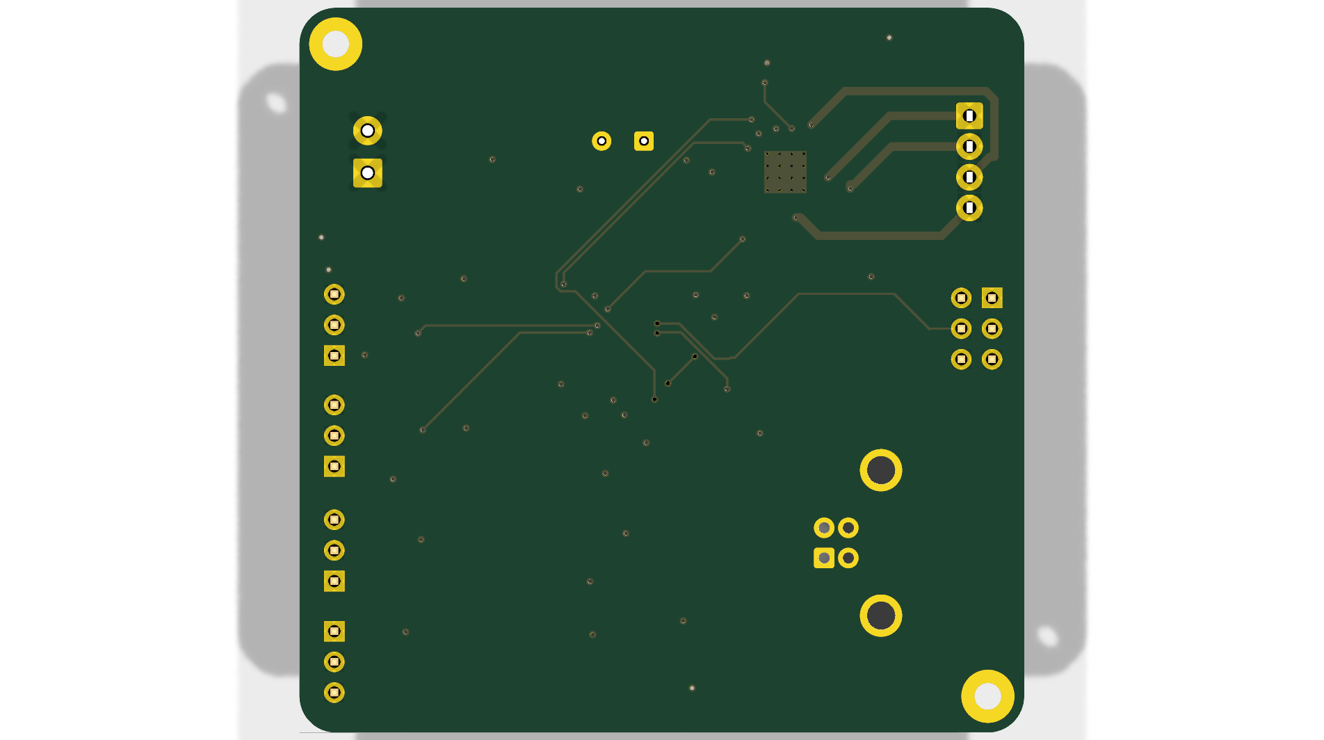 |
flowchart TD
    subgraph Power_Subsystem ["Power Distribution Network (PDN)"]
        VIN["Motor Power (4.75V - 29V)<br/>Terminal Block J8"] --> BulkCap["Bulk Decoupling<br/>100µF Radial + 2x 100nF"]
        BulkCap --> VMOT["VMOT Supply Rail"]
        VMOT --> LDO["NCP1117-5.0 LDO<br/>(Steps to +5V Logic)"]
        USB["USB Type-B Port (J2)"] --> Schottky["SS14 Schottky Diode (D3)"]
        Schottky --> VCC5["+5V System VCC Rail"]
        LDO --> VCC5
    end

    subgraph MCU_Subsystem ["Microcontroller & Communications"]
        VCC5 --> MCU["ATmega328P-A (TQFP-32)<br/>16.000 MHz Clock"]
        CH340["CH340K USB-UART (U2)"] <-->|"UART RX/TX + DTR Reset"| MCU
        ICSP["6-Pin AVR ISP Header (J1)"] <-->|"SPI MOSI/MISO/SCK/RST"| MCU
        MCU --> LEDS["Power & Diagnostic LEDs<br/>(D1, D2)"]
    end

    subgraph Motion_Subsystem ["Silent Motion Control"]
        VMOT --> TMC["Trinamic TMC2209-LA (U3)<br/>Silent Stepper Driver"]
        VCC5 --> TMC
        MCU -->|"M1_STEP / M1_DIR / EN"| TMC
        MCU <-->|"PD_UART (Single-Wire)"| TMC
        TMC --> SenseRes["Dual 0.11Ω 1210 Sense Resistors<br/>(R13, R14)"]
TMC --> MotorOut["4-Phase Stepper Terminal (J7)<br/>(A1, A2, B1, B2)"]| Specification | Parameter Value | Engineering Notes |
|---|---|---|
| Board Footprint | $60.00\text{ mm} \times 60.00\text{ mm}$ | Compact square profile with 3.0 mm radius rounded corners |
| Mounting Pattern | 4× M3 Mounting Holes | Positioned at corners for rigid enclosure mounting |
| Layer Stackup | 2-Layer FR-4 (1.6 mm thickness) | Top signal/routing + solid bottom GND return plane |
| Motor Input Voltage ($V_S$) | 4.75V to 29.0V DC | Accepts standard 12V or 24V industrial/3D-printer power supplies |
| Motor Peak Current | 2.8A Peak / 2.0A RMS | Configurable in software via TMC2209 internal registers |
| Current Sense Resistors | Dual $0.11\ \Omega \pm 1%$ (1210 SMT) | High power dissipation footprint for thermal stability |
| Microstepping Modes | Up to 1/256 | Native 1/16 with MicroPlyer™ interpolation to 1/256 |
| Microcontroller | ATmega328P-A (TQFP-32) | 32 KB Flash, 2 KB SRAM, 1 KB EEPROM @ 16 MHz |
| USB Interface | CH340K (SSOP-10) | Built-in clock, requires no external crystal |
| Design Rule Check (DRC) | 0 Errors, 0 Unconnected Items | 100% compliant with standard 2-layer PCB fabrication rules |
| ATmega328P Pin | Net Name | Hardware Function / Target Peripheral |
|---|---|---|
| Pin 1 (PD3) | M1_STEP | Step pulse command to TMC2209 Pin 16 |
| Pin 2 (PD4) | M1_DIR | Direction pulse command to TMC2209 Pin 17 |
| Pin 9 (PB6) | XTAL1 | 16.000 MHz Crystal Oscillator ($Y1$) |
| Pin 10 (PB7) | XTAL2 | 16.000 MHz Crystal Oscillator ($Y1$) |
| Pin 11 (PD5) | EN | Motor output enable/disable (active low) to TMC2209 Pin 18 |
| Pin 12 (PD6) | PD_UART | Half-duplex single-wire UART communication with TMC2209 Pin 20 |
| Pin 13 (PD7) | DIAGNOSTIC | StallGuard / fault flag input from TMC2209 Pin 22 |
| Pin 15 (PB1) | DIGITAL_IN1 | Filtered digital input via header $J5$ (RC filtered) |
| Pin 16 (PB2) | DIGITAL_IN2 | Filtered digital input via header $J6$ (RC filtered) |
| Pin 17 (PB3) | MOSI | SPI Master Out / In-System Programming ($J1$) |
| Pin 18 (PB4) | MISO | SPI Master In / In-System Programming ($J1$) |
| Pin 19 (PB5) | SCK | SPI Clock / In-System Programming ($J1$) |
| Pin 23 (PC0) | ANALOG_IN3 | Filtered analog/digital input via header $J3$ |
| Pin 24 (PC1) | ANALOG_IN4 | Filtered analog/digital input via header $J4$ |
| Pin 29 (PC6) | RESET | Active-low reset tied to tactile switch $SW1$ and CH340K DTR line |
| Pin 30 (PD0) | RXD (UART-) | Hardware UART receive from CH340K USB bridge |
| Pin 31 (PD1) | TXD (UART+) | Hardware UART transmit to CH340K USB bridge |
| Connector | Type | Net Connections | Function |
|---|---|---|---|
| J1 | 2×3 2.54mm Header | MOSI, MISO, SCK, RESET, VCC, GND | Standard AVR ICSP programming port |
| J2 | USB Type-B Female | VBUS, D-, D+, GND | PC programming and USB serial communication |
| J3 | 1×3 2.54mm Header | VCC, ANALOG_IN3 (filtered), GND | Sensor / Potentiometer input |
| J4 | 1×3 2.54mm Header | VCC, ANALOG_IN4 (filtered), GND | Sensor / Limit switch input |
| J5 | 1×3 2.54mm Header | VCC, DIGITAL_IN1 (filtered), GND | Optical / Mechanical Endstop input |
| J6 | 1×3 2.54mm Header | VCC, DIGITAL_IN2 (filtered), GND | Optical / Mechanical Endstop input |
| J7 | 4-Pin 2.54mm Screw Terminal | Motor Coils: A1, A2, B1, B2 | Stepper motor phase output |
| J8 | 2-Pin 3.5mm Screw Terminal | VIN ($4.75\text{V} - 29\text{V}$), GND | Main motor power supply input |
| Asset Category | File Path | Description |
|---|---|---|
| Schematic Vector PDF | schematic/ATmega_TMC2209_Schematic.pdf | High-resolution printable schematic |
| Schematic Vector SVG | schematic/ATmega_TMC2209_Schematic.svg | Scalable vector graphic of complete circuit |
| Bill of Materials | manufacturing/ATmega_TMC2209_BOM.csv | Full component list with footprints and quantities |
| Fabrication Package | manufacturing/ATmega_TMC2209_Gerbers_Rev1.zip | Production gerbers & Excellon drill file |
| KiCad 10 Project | hardware/ | Native .kicad_pro, .kicad_sch, and .kicad_pcb CAD files |
| Qty | Value | Footprint | References |
|---|---|---|---|
| 16 | 100nF | Capacitor_SMD:C_0805_2012Metric | C1, C3, C4, C5, C7, C8, C9, C10, C11, C12, C13, C14, C15, C16, C18, C20 |
| 5 | 1kΩ | Resistor_SMD:R_0805_2012Metric | R2, R3, R10, R11, R12 |
| 4 | R_FILTER 1.5kΩ | Resistor_SMD:R_0805_2012Metric | R6, R7, R8, R9 |
| 2 | 0.11Ω | Resistor_SMD:R_1210_3225Metric | R13, R14 |
| 2 | 22pF | Capacitor_SMD:C_0805_2012Metric | C2, C6 |
| 2 | MountingHole | MountingHole:MountingHole_2.2mm_M2_Pad | H3, H4 |
| 1 | 100uF | Capacitor_THT:CP_Radial_D8.0mm_P3.50mm | C19 |
| 1 | 10kΩ | Resistor_SMD:R_0805_2012Metric | R1 |
| 1 | 16MHz | Crystal:Crystal_SMD_5032-2Pin_5.0x3.2mm | Y1 |
| 1 | 4.7uF | Capacitor_SMD:CP_Elec_4x5.3 | C17 |
| 1 | ATmega328P-A | Package_QFP:TQFP-32_7x7mm_P0.8mm | U1 |
| 1 | CH340K | Package_SO:SSOP-10-1EP_3.9x4.9mm_P1mm_EP2.1x3.3mm | U2 |
| 1 | DIAGNOSTIC | LED_SMD:LED_0805_2012Metric | D2 |
| 1 | ISP | Connector_PinHeader_2.54mm:PinHeader_2x03_P2.54mm_Vertical | J1 |
| 1 | J_IN1 | Connector_PinHeader_2.54mm:PinHeader_1x03_P2.54mm_Vertical | J5 |
| 1 | J_IN2 | Connector_PinHeader_2.54mm:PinHeader_1x03_P2.54mm_Vertical | J6 |
| 1 | J_IN3 | Connector_PinHeader_2.54mm:PinHeader_1x03_P2.54mm_Vertical | J3 |
| 1 | J_IN4 | Connector_PinHeader_2.54mm:PinHeader_1x03_P2.54mm_Vertical | J4 |
| 1 | LOGO | LOGO | G*** |
| 1 | NCP1117-5.0_SOT223 | Package_TO_SOT_SMD:SOT-223-3_TabPin2 | U4 |
| 1 | Output_Phases | TerminalBlock_Phoenix:TerminalBlock_Phoenix_MPT-0,5-4-2.54_1x04_P2.54mm_Horizontal | J7 |
| 1 | POWER_LED | LED_SMD:LED_0805_2012Metric | D1 |
| 1 | Power_Input | TerminalBlock_Phoenix:TerminalBlock_Phoenix_PT-1,5-2-3.5-H_1x02_P3.50mm_Horizontal | J8 |
| 1 | Reset_Button | Button_Switch_SMD:SW_SPST_TS-1088-xR020 | SW1 |
| 1 | SS14 | Diode_SMD:D_SMA | D3 |
| 1 | TMC2209-LA | Package_DFN_QFN:VQFN-28-1EP_5x5mm_P0.5mm_EP3.7x3.7mm_ThermalVias | U3 |
| 1 | USB_B | Connector_USB:USB_B_OST_USB-B1HSxx_Horizontal | J2 |

AMOVFC/PanTilt
Three projects live in this folder. They share NewLibrary.kicadsym, TMC2209.pretty and the same philosophy: nothing on the board needs precision placement, every active part is a module in a socket.

udu3324/stepper-synth
An electronic instrument that uses stepper motors to make music

ANSHUMANDOCX/Spot-Welder-with-MCU
this is a spot welder for 18650 batteries made using mosfets along with a atemga328p and rotary encoder along with a display and a 12v lead acid battery


Ermakov/CrealitySpacePiAutomation
Creality Space Pi Plus CFS mod automation (PCB and sketch for Arduino IDE)

It measures 60 × 60 mm and has 4 copper layers, 1.6 mm thick.
52 parts, built around the ATMEGA328P-AU, CH340K, TMC2209-LA and SS14. The full list of its parts is on this page, with links to each part's symbol and footprint where PCBKit's library has them.
From the sbbxiii/The-Armadillo repository on GitHub, at the commit this page was made from: the board is hardware/ATmega_TMC2209_Driver.kicad_pcb and its schematic hardware/ATmega_TMC2209_Driver.kicad_sch. PCBKit opens the board in the browser, with nothing to install.
Its repository publishes it under the MIT licence: you may reuse it on that licence's terms (keep the author's notice, and for a copyleft licence share your changes alike).