4 layers27 × 27 mm
O32controller
qwertpas/O32controller
Miniature closed-loop controller for brushless DC motors
88 parts37MIT
 qwertpas/O32controller37
Miniature closed-loop controller for brushless DC motors
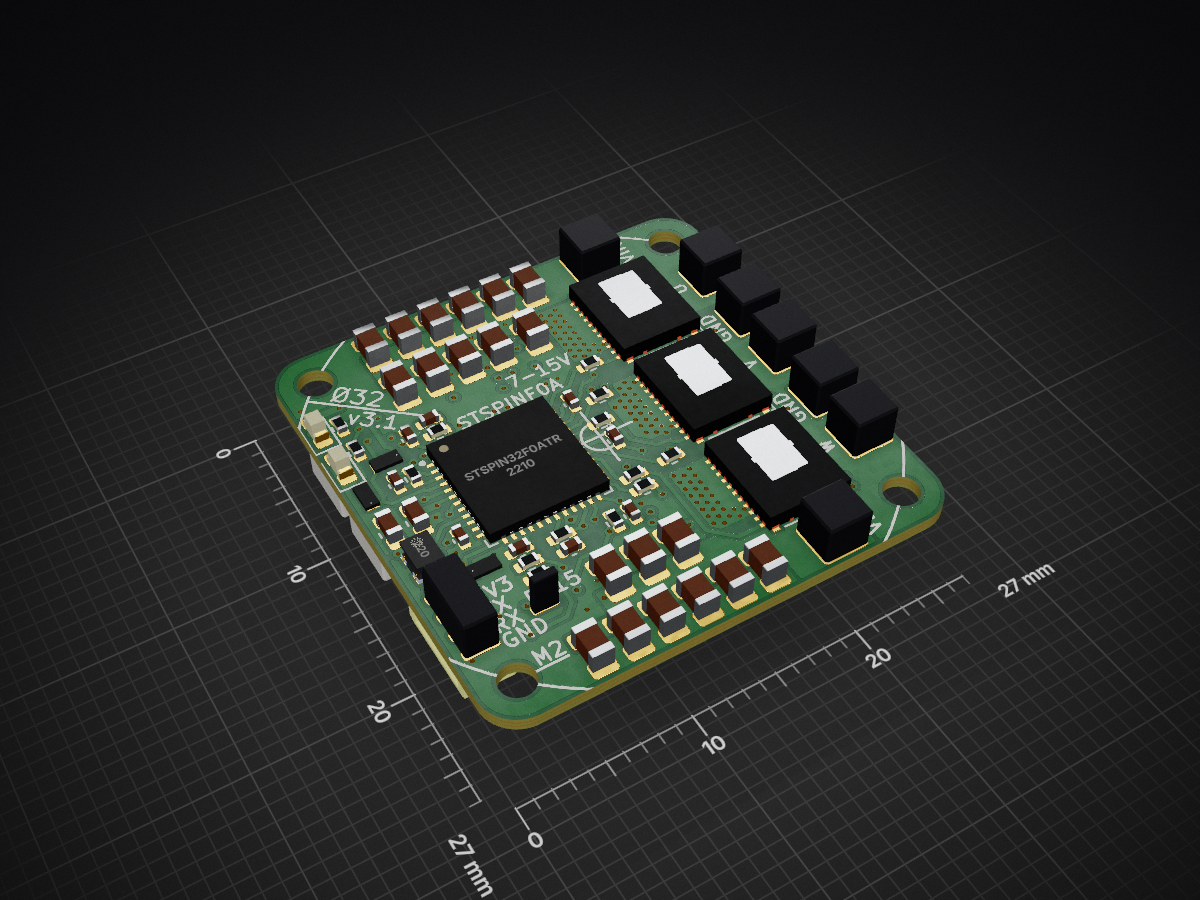
O32controller is an open-source printed circuit board by qwertpas, from the qwertpas/O32controller repository on GitHub, published under the MIT licence. It is a 4-layer board of 27 × 27 mm with 126 parts on 86 nets, routed with 812 tracks and 211 vias.
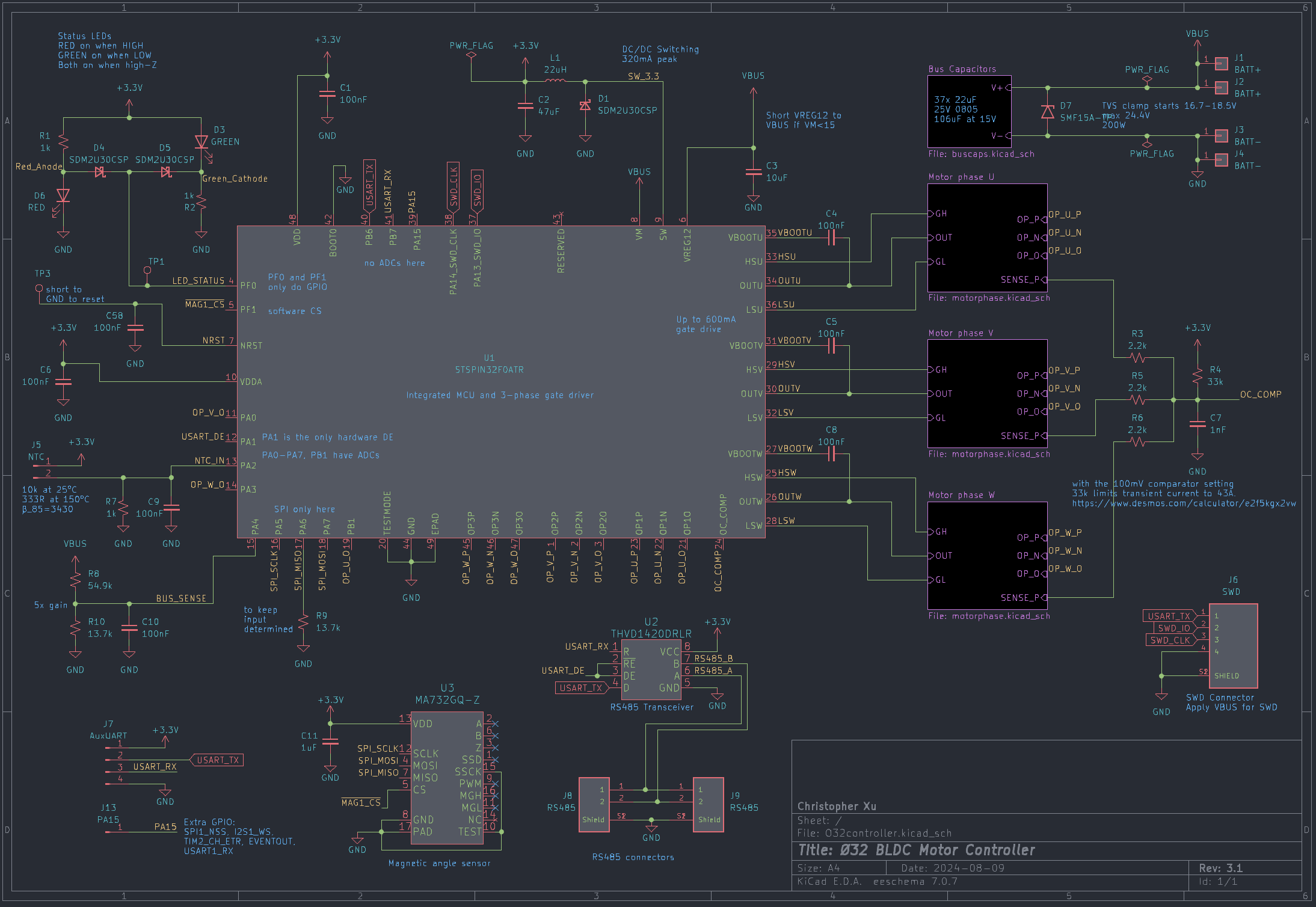
It is built around the CSD88584Q5DC, MA732GQ-Z and CL21A226MAQNNNE, with the SR0402FR-7T10RL, CC0402MRX7R9BB102 and CRCW04022R20JNEDHP among its other parts. Its parts include 58 capacitors, 37 resistors, 13 connectors, 6 diodes and 3 ICs. It belongs with the robots and motor control boards and the STM32 boards of this library.


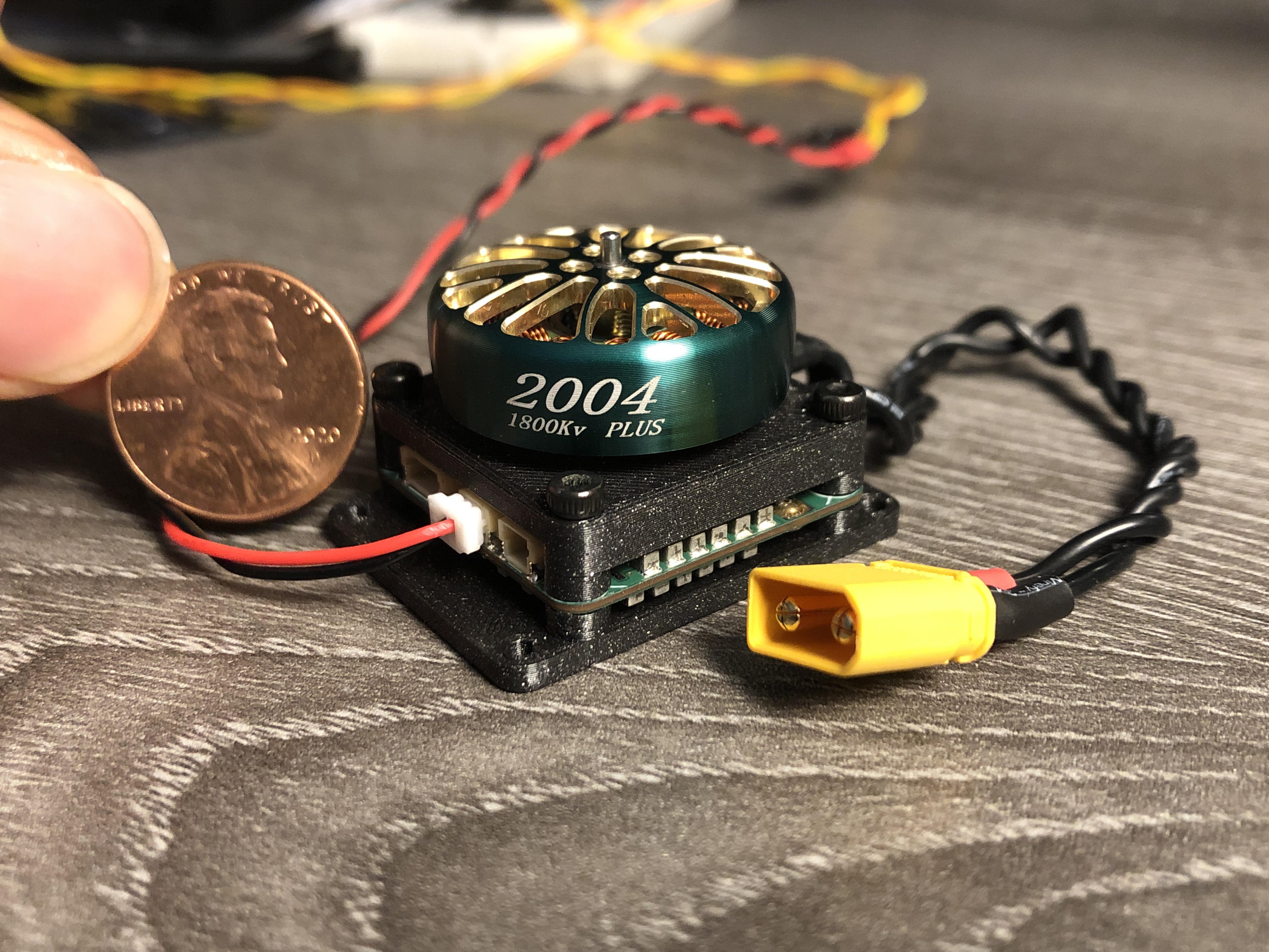
Small robots often use servos or small brushed DC motors, but they are not as power dense as the brushless DC (BLDC) motors commonly found in drones. Called the Ø32 because the M2 mounting holes are on a 32mm diameter circle, this project controls 7-15V motors with accurate position feedback and field-oriented control (FOC), while fitting almost completely behind a 2304 or larger drone motor.
Specs:
Critical components:
More info on Hackaday.io: https://hackaday.io/project/189115-32-bldc-controller
Firmware here: https://github.com/qwertpas/O32controller_FW
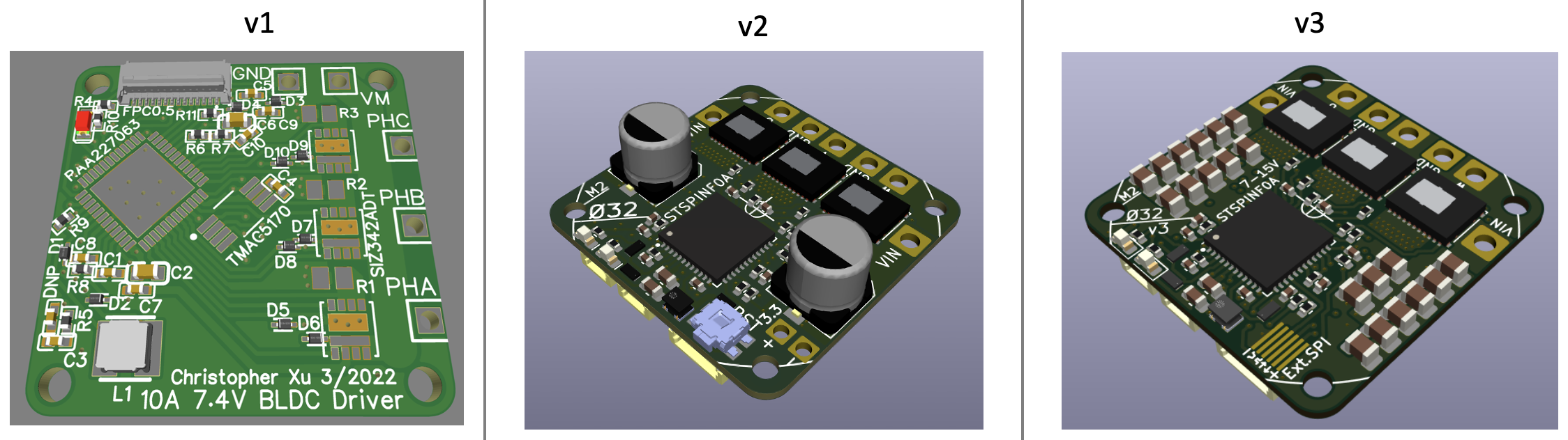
Changelog from v3 to v3.1:
Changelog from v2 to v3:
| Qty | Value | Footprint | References |
|---|---|---|---|
| 37 | 22uF | O32controller:C_0805_nosilk | C21, C22, C23, C24, C25, C26, C27, C28, C29, C30, C31, C32, C33, C34, C35, C36 +21 |
| 8 | 100nF | Capacitor_SMD:C_0402_1005Metric | C1, C4, C5, C6, C8, C9, C10, C58 |
| 6 | 1.78k | Resistor_SMD:R_0402_1005Metric | R15, R17, R24, R26, R33, R35 |
| 6 | 10R | Resistor_SMD:R_0402_1005Metric | R11, R13, R20, R22, R29, R31 |
| 6 | 27.4k | Resistor_SMD:R_0402_1005Metric | R14, R16, R23, R25, R32, R34 |
| 5 | 13.7k | Resistor_SMD:R_0402_1005Metric | R9, R10, R19, R28, R37 |
| 4 | 1nF | Capacitor_SMD:C_0402_1005Metric | C7, C14, C17, C20 |
| 3 | 10nF | Capacitor_SMD:C_0402_1005Metric | C12, C15, C18 |
| 3 | 1k | Resistor_SMD:R_0402_1005Metric | R1, R2, R7 |
| 3 | 2.2R | Resistor_SMD:R_0402_1005Metric | R12, R21, R30 |
| 3 | 2.2k | Resistor_SMD:R_0402_1005Metric | R3, R5, R6 |
| 3 | 4.7nF | Capacitor_SMD:C_0402_1005Metric | C13, C16, C19 |
| 3 | CSD88584Q5DC | O32controller:CSD88584Q5DCT | Q1, Q2, Q3 |
| 3 | Motor Connection | O32controller:SolderWire-Actual_1x01_D1.7mm_OD_2.75mm | J10, J11, J12 |
| 3 | PU2512FKMP50R002L | O32controller:R_Shunt_2512_6332Metric | R18, R27, R36 |
| 3 | SDM2U30CSP | O32controller:SDM2U30CSP-7 | D1, D4, D5 |
| 3 | Sense_N | O32controller:NetTie-2_SMD_Pad0.25mm | NT1, NT2, NT3 |
| 2 | BATT+ | O32controller:SolderWire-Actual_1x01_D1.7mm_OD_2.75mm | J1, J2 |
| 2 | BATT- | O32controller:SolderWire-Actual_1x01_D1.7mm_OD_2.75mm | J3, J4 |
| 2 | RS485 | O32controller:JST_SM02B-SRSS-TB(LF)(SN) | J8, J9 |
| 2 | TestPoint | O32controller:TestPoint_Pad_Rect | TP1, TP3 |
| 1 | 10uF | Capacitor_SMD:C_0603_1608Metric | C3 |
| 1 | 121k | Resistor_SMD:R_0402_1005Metric | R4 |
| 1 | 1uF | Capacitor_SMD:C_0402_1005Metric | C11 |
| 1 | 22uH | O32controller:IND_VLS201612CX-220M-1 | L1 |
| 1 | 47uF | Capacitor_SMD:C_0603_1608Metric | C2 |
| 1 | 54.9k | Resistor_SMD:R_0402_1005Metric | R8 |
| 1 | AuxUART | O32controller:SolderUART-1.27mm | J7 |
| 1 | GREEN | LED_SMD:LED_0603_1608Metric | D3 |
| 1 | MA732GQ-Z | O32controller:QFN-16_MA732 | U3 |
| 1 | NTC | O32controller:SolderNTC-1.27mm | J5 |
| 1 | PA15 | O32controller:SolderPad1-1.27mm | J13 |
| 1 | RED | LED_SMD:LED_0603_1608Metric | D6 |
| 1 | SMF15A | Diode_SMD:D_SMF | D7 |
| 1 | STSPIN32F0ATR | O32controller:VFQFPN-48-1EP_7x7mm_P0.5mm_EP2.8x2.8mm | U1 |
| 1 | SWD | O32controller:JST_SM04B-SRSS-TB(LF)(SN) | J6 |
| 1 | THVD1420DRLR | O32controller:THVD1420DRLR_SOT-585 | U2 |
It measures 27 × 27 mm and has 4 copper layers, 0.8 mm thick.
126 parts, built around the CSD88584Q5DC, MA732GQ-Z, CL21A226MAQNNNE and SR0402FR-7T10RL. The full list of its parts is on this page, with links to each part's symbol and footprint where PCBKit's library has them.
From the qwertpas/O32controller repository on GitHub, at the commit this page was made from: the board is v3/O32controller.kicad_pcb and its schematic v2/O32controller.kicad_sch. PCBKit opens the board in the browser, with nothing to install.
Its repository publishes it under the MIT licence: you may reuse it on that licence's terms (keep the author's notice, and for a copyleft licence share your changes alike).
qwertpas/O32controller
Miniature closed-loop controller for brushless DC motors


alph4345/test
TrinketCore puts everything a small rechargeable gadget needs on one 40 × 60 mm board, ready to order assembled from PCBWay:


punkfab/pcb-corpus
235 real KiCad boards from open-source hardware repositories, prepared as a placement and routing benchmark


Def12345678/M-FC-G474-Rev-A
Modular STM32G474 Flight Controller Rev-A. Focus on modularity using JST-SH connectors for all peripherals (ESC, RX, etc.). ICM-42688-P IMU and DPS368 barometer. Requires external 5V 2.5A (no onboard BEC).

