6 layers60.6 × 100 mm
 lowdrant/kyber2
Extending/Retracting Lightsaber CAD/FW/EDA
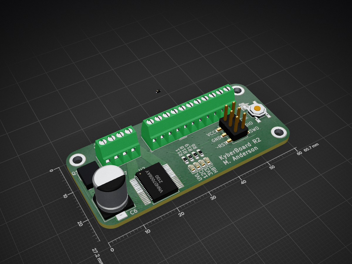
KyberBoard is an open-source printed circuit board by lowdrant, from the lowdrant/kyber repository on GitHub, published under the AGPL-3.0 licence. It is a 4-layer board of 60.7 × 27.2 mm with 71 parts on 59 nets, routed with 324 tracks and 68 vias.
It is built around the STM32L051K8T6, MMA8452QT and VNHD7008AY, with the AZ1117IH-3.3TRG1, SDM2U30CSP-7B and BZT585B3V6T among its other parts. Its parts include 18 capacitors, 17 resistors, 14 diodes, 5 transistors and 4 ICs. It belongs with the robots and motor control boards and the STM32 boards of this library.


The toy lightsaber I always wanted as a kid.
Written for the STM32L051K8T6 microcontroller. Code should work on any STM32 micrcontroller, and most interfaces are abstracted into header files.
TODO: state diagram
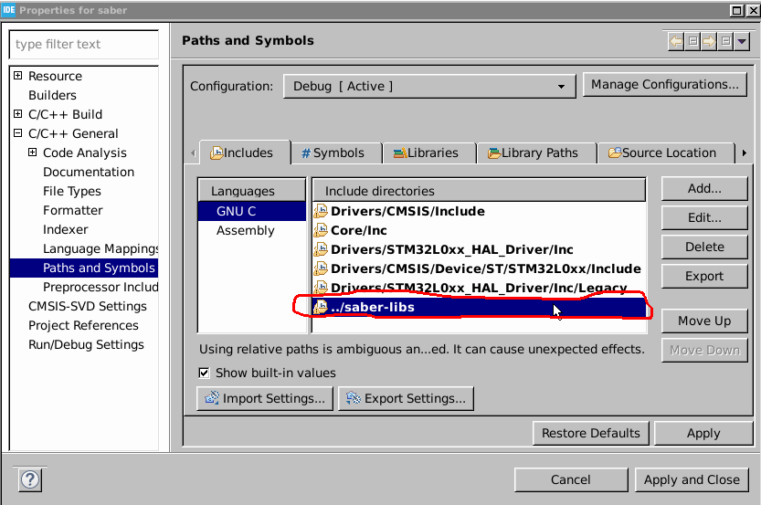
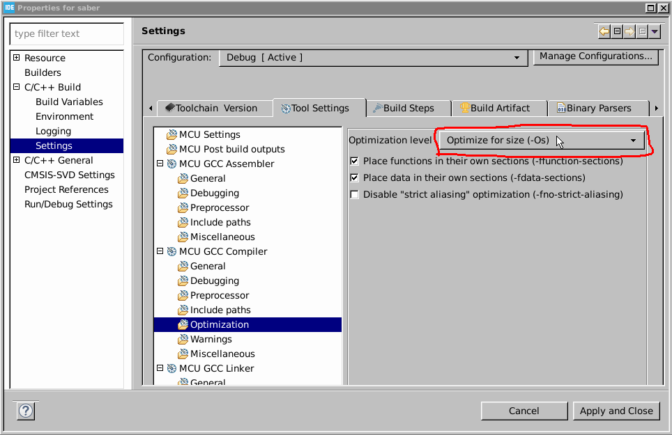
Edit project settings to include the multi-project libraries and make the compiler optimize for size. TODO: change saber-libs to holocron-libs
A mildly overdesigned PCB to allow flexibility in mechanical design. Designed for test, assembly, and reconfigurability.
Keep It Simple, Stupid. Stick to driving circuits that have readily available and easily solderable components. If necessary, target components that have in-stock evaluation boards and take the scrap.
| Component | Amperage | Reasoning |
|---|---|---|
| motor | 10A | stall current of on-hand dc motor |
| solenoid | 1A | 12 V/13 Ohms rounded up |
| 3V3 bus | 1A | typical LDO rating |
| waste | 0.5A | safety factor |
| ----------- | ---------- | --------------------------------- |
| total | 12.5A |
Mostly concerned with battery protection I2R losses. Target < 0.5V peak drop (instinctive spec, not computed)
Major concerns are
Current resolution: use ST's VNHD7008AY eval board example design. It seems to work fairly well
Use the built-in protection of the hbridge. Need to characterise I2R losses. This will help prevent the Big DumbTM since I plan to use terminal blocks for my main connector.
Grocery store batteries can't drive the actuators, so I'm looking at using a LiPo. This simple Zener-NMOS-PMOS circuit I designed for a student club will should prevent battery over-discharge.
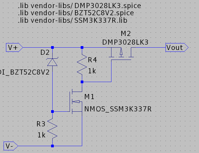
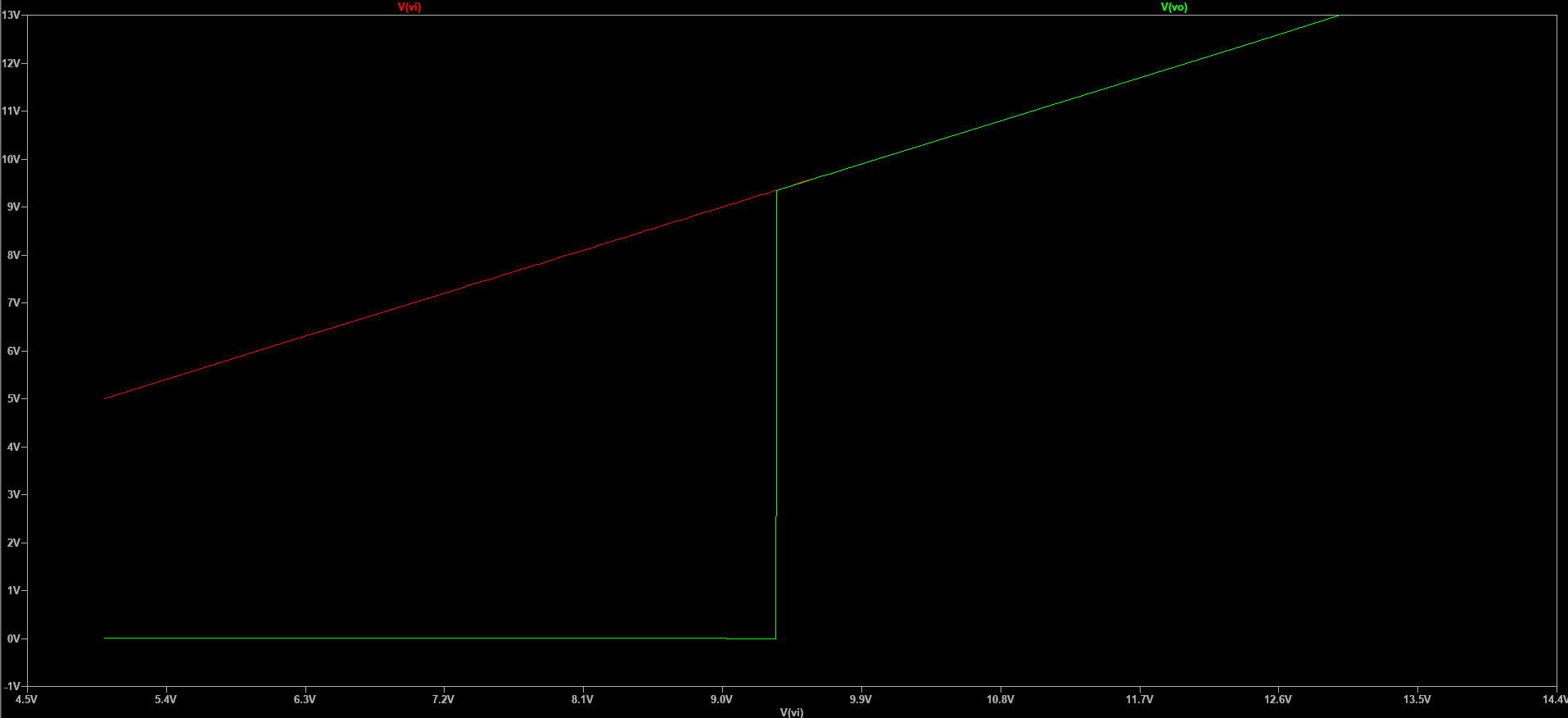 When the voltage is above Vthresh, the Zener conducts, so the NMOS conducts, which makes the PMOS conduct.
LDO; I do not want to deal with buck converters. I am not being paid for this design.
For that sweet, sweet zwoom. Use I2C/SPI to make routing a little easier. I have a still-in-stock breakout board for the no-longer-produced MMA84252QT.
I may use torque control to retract the saber. Currently planning to extend it with a spring, so the "retracted torque" is theoretically better characterized than the "retracted position".
I found a high-current hbridge IC that does not require complementary PWM (thank you ST). I have limited PWM capabilities due to only low-power ST micros being in stock.
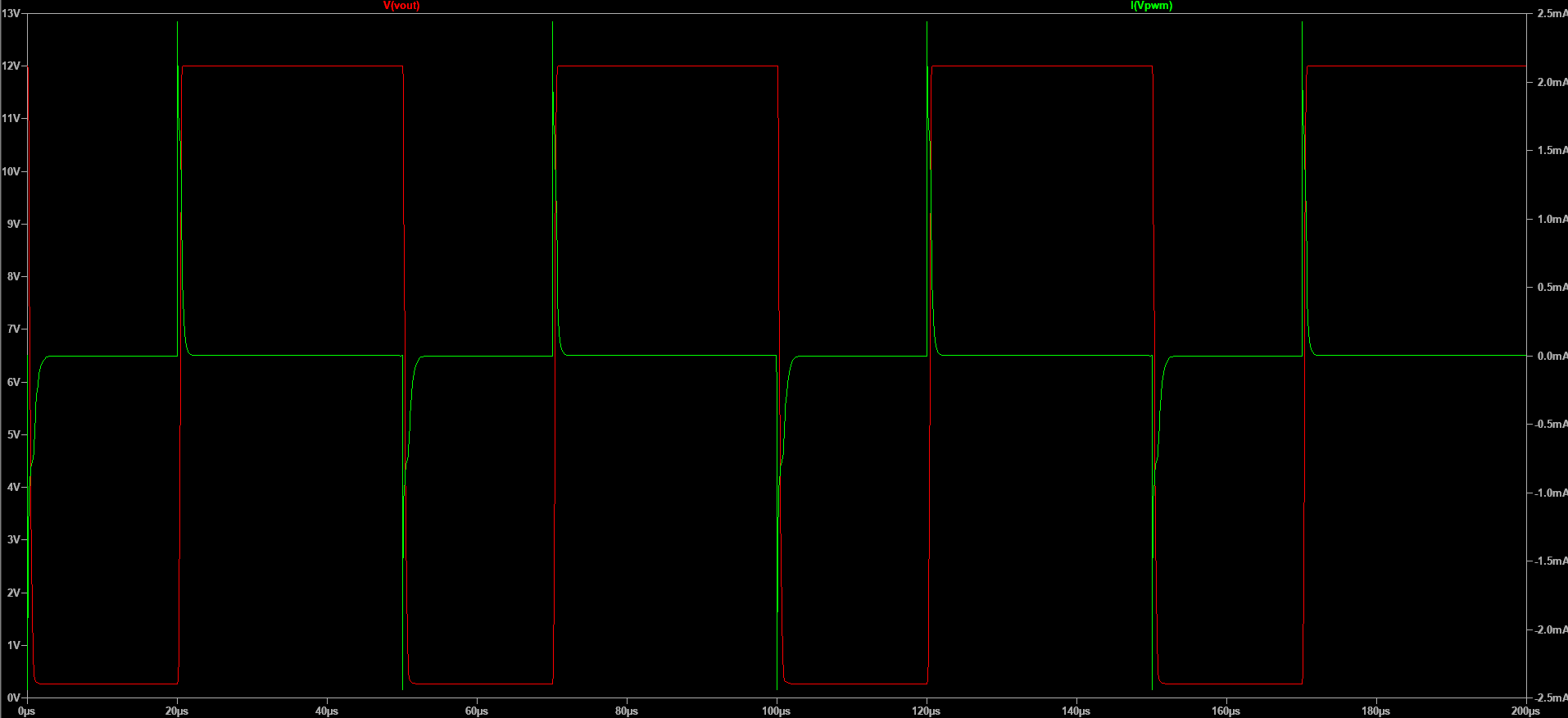
Low-side switches that do not require inrush-limiting resistors to reduce component count. The SSM3K337R,LF stays well under the maximum drive current and well-preserves a 20kHz square wave.
Found a Luke Skywalker lightsaber CAD for 3D printing by CaseStudyno8. Was also pointed to Disney's new lightsaber, which shows some novel mechanical design for retraction. Although I would prefer to be able to fence with my design, the tape measure strategy does show promise.
| Qty | Value | Footprint | References |
|---|---|---|---|
| 8 | 100n | Capacitor_SMD:C_0603_1608Metric_Pad1.05x0.95mm_HandSolder | C2, C4, C5, C7, C8, C15, C17, C18 |
| 8 | 1k | Resistor_SMD:R_0603_1608Metric_Pad1.05x0.95mm_HandSolder | R1, R2, R3, R6, R8, R10, R19, R20 |
| 5 | 10k | Resistor_SMD:R_0603_1608Metric_Pad1.05x0.95mm_HandSolder | R4, R11, R12, R13, R18 |
| 5 | SDM2U30CSP-7 | Diode_SMD:D_0603_1608Metric_Pad1.05x0.95mm_HandSolder | D4, D5, D6, D7, D9 |
| 4 | BZT585B3V6T | Diode_SMD:D_SOD-523 | D8, D13, D14, D15 |
| 3 | 10n | Capacitor_SMD:C_0603_1608Metric_Pad1.05x0.95mm_HandSolder | C9, C10, C11 |
| 3 | MountingHole_Pad | MountingHole:MountingHole_2.7mm_M2.5_ISO7380_Pad | H1, H3, H4 |
| 2 | 0 | Resistor_SMD:R_0402_1005Metric | R16, R17 |
| 2 | 10u | Capacitor_SMD:C_0603_1608Metric_Pad1.05x0.95mm_HandSolder | C3, C12 |
| 2 | 150060AS75000 | LED_SMD:LED_0603_1608Metric_Pad1.05x0.95mm_HandSolder | D10, D11 |
| 1 | |||
| 1 | 0 | Resistor_SMD:R_0603_1608Metric_Pad1.05x0.95mm_HandSolder | R9 |
| 1 | 150060RS75020 | LED_SMD:LED_0603_1608Metric_Pad1.05x0.95mm_HandSolder | D3 |
| 1 | 150060VS75020 | LED_SMD:LED_0603_1608Metric_Pad1.05x0.95mm_HandSolder | D1 |
| 1 | 15910060 | Connector_PinHeader_2.54mm:PinHeader_2x03_P2.54mm_Vertical_SMD | J4 |
| 1 | 1k5 | Resistor_SMD:R_0603_1608Metric_Pad1.05x0.95mm_HandSolder | R5 |
| 1 | 1u | Capacitor_SMD:C_0603_1608Metric_Pad1.05x0.95mm_HandSolder | C19 |
| 1 | 200u | Capacitor_SMD:CP_Elec_8x10.5 | C6 |
| 1 | 22u | Capacitor_SMD:C_0603_1608Metric_Pad1.05x0.95mm_HandSolder | C13 |
| 1 | 33n | Capacitor_SMD:C_0603_1608Metric_Pad1.05x0.95mm_HandSolder | C1 |
| 1 | 4u7 | Capacitor_SMD:C_0603_1608Metric_Pad1.05x0.95mm_HandSolder | C16 |
| 1 | AZ1117IH-3.3TRG1 | Package_TO_SOT_SMD:SOT-223-3_TabPin2 | U3 |
| 1 | BZT52C8V2S-7-F | Diode_SMD:D_SOD-323_HandSoldering | D2 |
| 1 | CIGT201210UHR47MNE | Capacitor_SMD:C_0805_2012Metric | L1 |
| 1 | LOGO | easter-eggs:starfleet | G*** |
| 1 | LOGO | easter-eggs:qr-funeral-pyre | G*** |
| 1 | LOGO | easter-eggs:velociraptor | G*** |
| 1 | MMA8452QT | MMA8452:MMA8452Q | U4 |
| 1 | SIS413DN-T1-GE3 | Package_SO:Vishay_PowerPAK_1212-8_Single | Q2 |
| 1 | SSM3K337R | Package_TO_SOT_SMD:SOT-23 | Q3 |
| 1 | SSM3K337R,LF | Package_TO_SOT_SMD:SOT-23 | Q7 |
| 1 | STL120N4F6AG | STL120N4F6AG:STL120N4F6AG | Q1 |
| 1 | STL76DN4LF7AG | STL76DN4LF7AG:STL76DN4LF7AG | Q4 |
| 1 | STM32L051K8T6 | Package_QFP:LQFP-32_7x7mm_P0.8mm | U1 |
| 1 | Screw_Terminal_01x04 | TerminalBlock_Phoenix:TerminalBlock_Phoenix_MPT-0,5-4-2.54_1x04_P2.54mm_Horizontal | J1 |
| 1 | Screw_Terminal_01x11 | TerminalBlock_Phoenix:TerminalBlock_Phoenix_MPT-0,5-11-2.54_1x11_P2.54mm_Horizontal | J2 |
| 1 | TL3342F160QG/TR | Button_Switch_SMD:SW_SPST_TL3342 | SW1 |
| 1 | TestPoint | TestPoint:TestPoint_Pad_2.0x2.0mm | TP1 |
| 1 | VNHD7008AY | Package_SO:ST_PowerSSO-36_SlugDown_ThermalVias | U2 |
It measures 60.7 × 27.2 mm and has 4 copper layers, 1.6 mm thick.
71 parts, built around the STM32L051K8T6, MMA8452QT, VNHD7008AY and AZ1117IH-3.3TRG1. The full list of its parts is on this page, with links to each part's symbol and footprint where PCBKit's library has them.
From the lowdrant/kyber repository on GitHub, at the commit this page was made from: the board is hw/KyberBoard/KyberBoard.kicad_pcb. PCBKit opens the board in the browser, with nothing to install.
Its repository publishes it under the AGPL-3.0 licence: you may reuse it on that licence's terms (keep the author's notice, and for a copyleft licence share your changes alike).

AndreasNielsen4000/Group-7-IoT-Project
The project is a wireless speaker system that can play music from a Bluetooth or WiFi source. The system consists of four main parts with subcomponents:

qwertpas/O32controller
Miniature closed-loop controller for brushless DC motors

Def12345678/M-FC-G474-Rev-A
Modular STM32G474 Flight Controller Rev-A. Focus on modularity using JST-SH connectors for all peripherals (ESC, RX, etc.). ICM-42688-P IMU and DPS368 barometer. Requires external 5V 2.5A (no onboard BEC).


Estylos/Light-Doorbell-HW
KiCad project for a custom, battery-powered doorbell with dual-color LED feedback and 4-layer circular PCB design. Optimized for low power and compact integration

ArgonautGit/wallet_dmm
A multimeter the size of a credit card: DC volts, resistance, continuity and diode test, shown on a 0.91" OLED, with three buttons, an RGB LED and a piezo beeper.