4 layers100 × 83 mm
Module17-Mainboard
M17-Project/Module_17
M17 modem board for 9600-baud capable radios
209 parts129CERN-OHL-W-2.0

 M17-Project/Micro1720
M17 baseband processor board - OpenRTX on a Module
Micro17 is an open-source printed circuit board by M17-Project, from the M17-Project/Micro17 repository on GitHub. It is a 4-layer board of 20 × 30 mm with 93 parts on 112 nets, routed with 526 tracks and 113 vias.
It is built around the STM32G473CEU6, MCP6002T-E/MC and CPC1117N, with the MCP4451-503E/ST, XC6220B331MR and 0402B104K250NT among its other parts. Its parts include 35 capacitors, 29 resistors, 7 ICs, 3 connectors and 1 diode. It belongs with the STM32 boards of this library.


Variant of Micro17 for ICOM IC-F commercial radios. Compatible model list is available here.
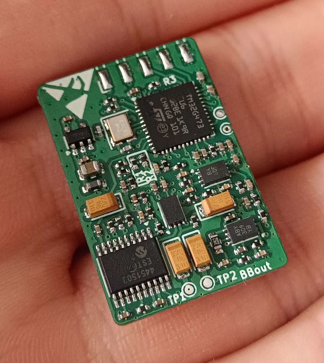
WIP - ST-Link needed
A Youtube video guide is planned soon:tm:.
Getting inside mobile IC-F5X6X/6X6X is quite straightforward: four screws will allow you to pop the bottom cover off. You'll need to cut/solder the following bridges:
You can then install Micro17 in the J1 slot.
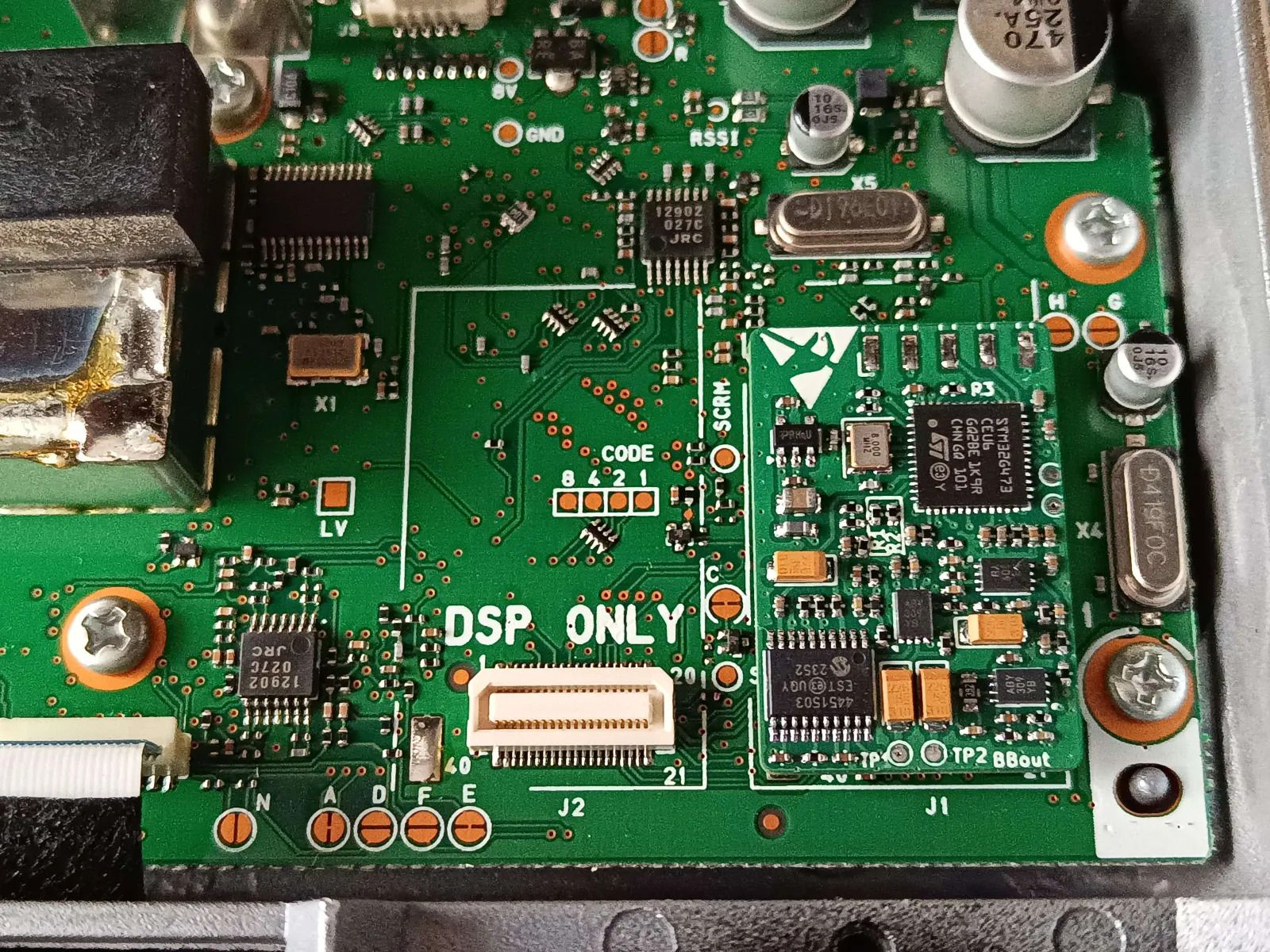
Opening a handset is a bit trickier. You'll need to remove the two knobs, unscrew the antenna nut (either using thin needle-nose pliers or the appropriate tool. Be careful as it might be glued, some light blasting with a heat gun might be needed) and the two bottom screws behind the battery. The following bridges will have to be changed:
As this module is embedded inside the radio, configuration is pulled from the radio's "codeplug". This is still heavily WIP, but it's planned to use the internal command protocol one the details get figured out.
This variant is based on the experiments documented here. The internal J1 connector breaks out all necessary pins.
| Module17 equivalent Pins | J1 connector |
|---|---|
| GND (DB9 - pin 8) | Pin 2, 17 or 39 - GND |
| +12V/+8V (DB9 - pin 9) | Pin 37 - VCC |
| RX (DB9 - pin 6) | Pin 31 - DISC |
| TX (DB9 - pin 2) | Pin 13 - SIGO |
| PTT_OUT (DB9 - pin 5) | Pin 4 - PTTO (Add a 1K pullup to 5V - pin 38!) |
| AF_OUT (pot middle pin) | Pin 30 - AFOUT |
| MIC_IN (jack's middle pin) | Pin 7 - MCIN |
| PTT_IN (jack's last pin) | Pin 3 - PTTIN (Through a resistive divider: two 2.7k resistors in series between pins 2 and 3, wire to Module17 in the middle) |
| Qty | Value | Footprint | References |
|---|---|---|---|
| 12 | GP | TestPoint:TestPoint_Pad_D1.0mm | TP3, TP4, TP5, TP6, TP7, TP8, TP9, TP10, TP11, TP12, TP13, TP14 |
| 11 | 100n | Capacitor_SMD:C_0402_1005Metric | C4, C5, C6, C7, C8, C11, C13, C25, C30, C33, C35 |
| 8 | 10n | Capacitor_SMD:C_0402_1005Metric | C14, C15, C16, C19, C20, C24, C29, C31 |
| 6 | 22k | Resistor_SMD:R_0402_1005Metric | R17, R20, R21, R26, R27, R28 |
| 5 | 3k3 | Resistor_SMD:R_0402_1005Metric | R14, R18, R19, R22, R25 |
| 4 | 22u | Capacitor_Tantalum_SMD:CP_EIA-3216-18_Kemet-A | C26, C27, C28, C34 |
| 3 | 10k | Resistor_SMD:R_0402_1005Metric | R3, R4, R16 |
| 3 | 220n | Capacitor_SMD:C_0402_1005Metric | C12, C22, C23 |
| 3 | MCP6002 | Package_DFN_QFN:DFN-8-1EP_3x2mm_P0.5mm_EP1.75x1.45mm | U4, U6, U7 |
| 2 | 12k | Resistor_SMD:R_0402_1005Metric | R2, R29 |
| 2 | 13k | Resistor_SMD:R_0402_1005Metric | R8, R9 |
| 2 | 1n5 | Capacitor_SMD:C_0402_1005Metric | C17, C18 |
| 2 | 2p2 | Capacitor_SMD:C_0402_1005Metric | C1, C2 |
| 2 | 39k | Resistor_SMD:R_0402_1005Metric | R13, R23 |
| 2 | 4k3 | Resistor_SMD:R_0402_1005Metric | R6, R7 |
| 2 | 680p | Capacitor_SMD:C_0402_1005Metric | C21, C32 |
| 2 | 7k5 | Resistor_SMD:R_0402_1005Metric | R10, R11 |
| 1 | 10R | Resistor_SMD:R_0402_1005Metric | R5 |
| 1 | 1N4148WS | Diode_SMD:D_SOD-323 | D1 |
| 1 | 1u | Capacitor_SMD:C_0402_1005Metric | C9 |
| 1 | 22u/25V | Capacitor_SMD:C_0805_2012Metric | C10 |
| 1 | 2k2 | Resistor_SMD:R_0402_1005Metric | R15 |
| 1 | 2u2 | Capacitor_SMD:C_0402_1005Metric | C3 |
| 1 | 36k | Resistor_SMD:R_0402_1005Metric | R1 |
| 1 | 3k9 | Resistor_SMD:R_0603_1608Metric | R24 |
| 1 | 3k9 | Resistor_SMD:R_0402_1005Metric | R12 |
| 1 | 8 MHz | Crystal:Crystal_SMD_3225-4Pin_3.2x2.5mm | Y1 |
| 1 | AXK640347YG | micro17:AXK640347YG | J2 |
| 1 | CPC1117N | Package_SO:SOP-4_3.8x4.1mm_P2.54mm | U3 |
| 1 | Conn_01x05 | Connector_Harwin:Harwin_M20-89005xx_1x05_P2.54mm_Horizontal | J1 |
| 1 | FerriteBead_Small | Inductor_SMD:L_0603_1608Metric_Pad1.05x0.95mm_HandSolder | FB1 |
| 1 | Logo_Open_Hardware_Small | Symbol:OSHW-Logo_5.7x6mm_SilkScreen | SYM2 |
| 1 | MCP4451-503-ST | Package_SO:TSSOP-20_4.4x6.5mm_P0.65mm | U5 |
| 1 | STM32G473CCUx | Package_DFN_QFN:QFN-48-1EP_7x7mm_P0.5mm_EP5.6x5.6mm | U1 |
| 1 | SYM_ESD_Small | Symbol:ESD-Logo_6.6x6mm_SilkScreen | SYM1 |
| 1 | TP_RX | TestPoint:TestPoint_Pad_D1.0mm | TP1 |
| 1 | TP_TX | TestPoint:TestPoint_Pad_D1.0mm | TP2 |
| 1 | USB_B_Micro | Connector_USB:USB_Micro-B_Molex_47346-0001 | J4 |
| 1 | XC6220B331MR | Package_TO_SOT_SMD:SOT-23-5 | U2 |
It measures 20 × 30 mm and has 4 copper layers, 1.6 mm thick.
93 parts, built around the STM32G473CEU6, MCP6002T-E/MC, CPC1117N and MCP4451-503E/ST. The full list of its parts is on this page, with links to each part's symbol and footprint where PCBKit's library has them.
From the M17-Project/Micro17 repository on GitHub, at the commit this page was made from: the board is icom_ICF3_4_5_6XXX/micro17.kicad_pcb and its schematic generic/fltrs.kicad_sch. PCBKit opens the board in the browser, with nothing to install.
Its repository states no licence, so its author keeps all rights: ask M17-Project before reusing the design.
M17-Project/Module_17
M17 modem board for 9600-baud capable radios

qwertpas/O32controller
Miniature closed-loop controller for brushless DC motors

Infinest/AGBSUBS1-01
A Recreation of the AGBSUBS1-01 save board for the original AGB 64M (E201843), 128M (E201850) and 256M (E201868) dev cartridges by Nintendo

gallicchio/AMOD-and-RFMOD
The tutorial's 2x12 adapter (/mudd/133electronics/icepi-zero-dac-adc/adapterboard/) with a 2 x 6 right-angle Pmod socket on a 15 mm extension of its right-hand end, so an Icepi Zero can drive AMOD-A's and RF-MOD's Pmod…

Genabl/parasitic_monorepo
Second-board regression target for the volume-conductor pipeline.


Janky-Jingle-Crew/SouthPoleLevitator
2025 Christmas card "South Pole Levitator"

kaminaris/GigaESC-ControlBoard
Compact six-layer control card for modular GigaESC motor controllers. The MCU, CAN transceiver, IMU and signal conditioning live here; the MOSFET power stage and power supply are separate boards.