4 layers97 × 80.9 mm
Module17-HMI
M17-Project/Module_17
M17 modem board for 9600-baud capable radios
59 parts129CERN-OHL-W-2.0

 M17-Project/Module_17129
M17 modem board for 9600-baud capable radios
Module17-Mainboard is an open-source printed circuit board by M17-Project, from the M17-Project/Module_17 repository on GitHub, published under the CERN-OHL-W-2.0 licence. It is a 4-layer board of 100 × 83 mm with 209 parts on 151 nets, routed with 1,391 tracks and 1,236 vias.
It is built around the STM32F405RGT6V, MCP6002-I/SN and LM4991MA, with the MAX9814ETD+T, MCP4551-103E/MS and PTS645SH50SMTR92LFS among its other parts. Its parts include 73 resistors, 60 capacitors, 12 connectors, 8 ICs and 8 diodes. It belongs with the radio and wireless and computers and single-board computers boards and the STM32 boards of this library.


Welcome to Module 17 repository!
This project provides a standalone modem that transforms any 9600 baud capable transceiver into an M17 compatible radio. It is based on a STM32F4 microcontroller and is designed to run the OpenRTX firmware. Audio and PTT connectivity is given through a "Kenwood 2 Pin" compatible connector (2.5 and 3.5mm audio jacks) or an OHIS connector (this is NOT an internet connector). Power supply of 6 to 15 volts can be applied through a 5.5/2.5mm DC plug.
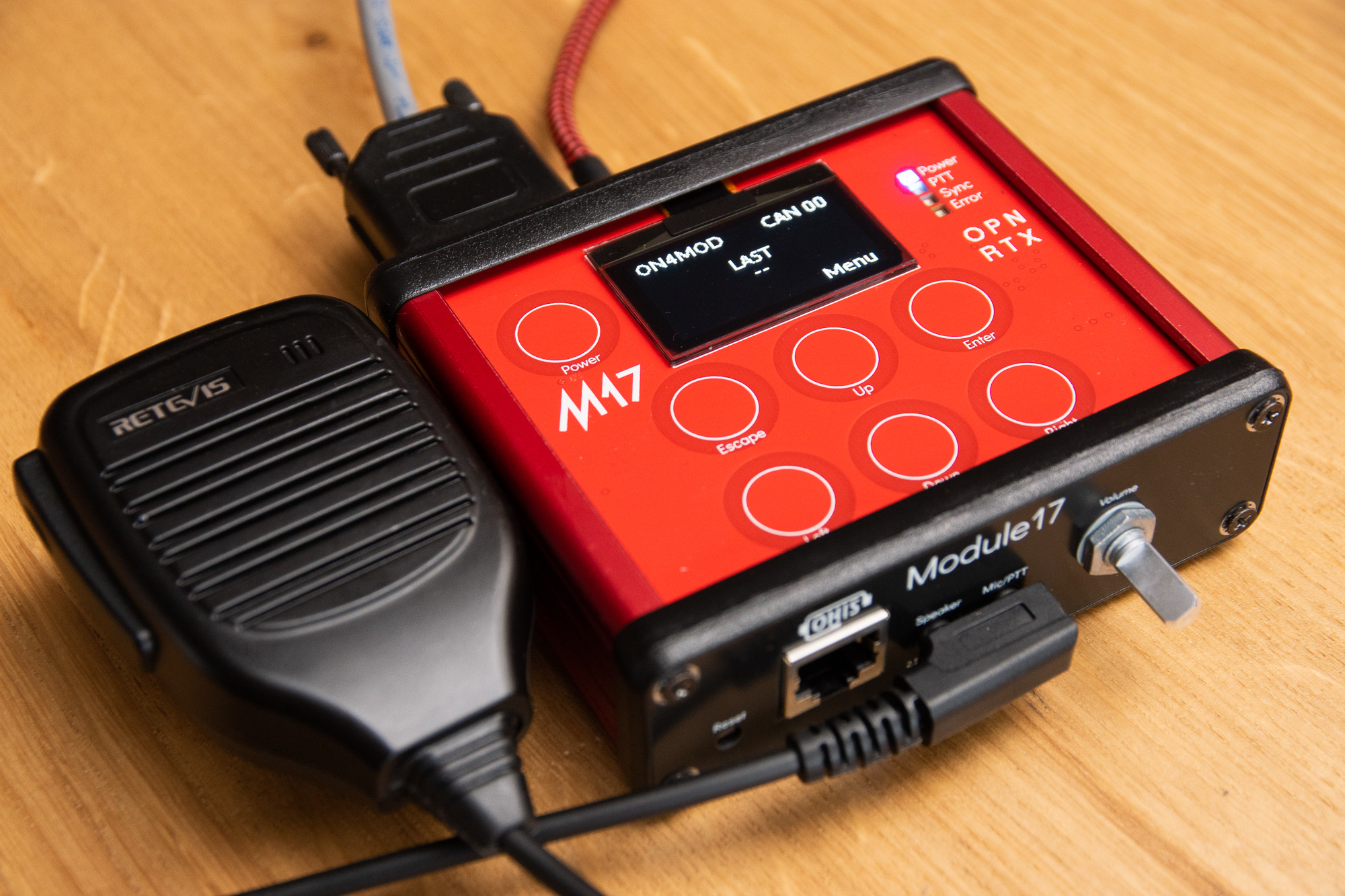
Several boards of various revisions have been built. The latest one is rev 1.0. This revision went through a complete board re-design, mainly to make it compatible with an aluminium extruded enclosure. It does however remain very similar in principle to the previous revisions. Other changes such as audio input and output improvements were made in this revision.
Revision 1.0 boards can be ordered partially or even fully assembled at PCBWay with the manufacturing data in this repository. Some parts such as the digital potentiometers, the DC-DC converter inductor or the audio power amplifier may not (always) be in stock. Fortunately, they are almost always available through Mouser/Digikey. JLCPCB can acquire them through their global sourcing program if you are willing to use it.
The current revision (rev 1.0) is available in two different versions:
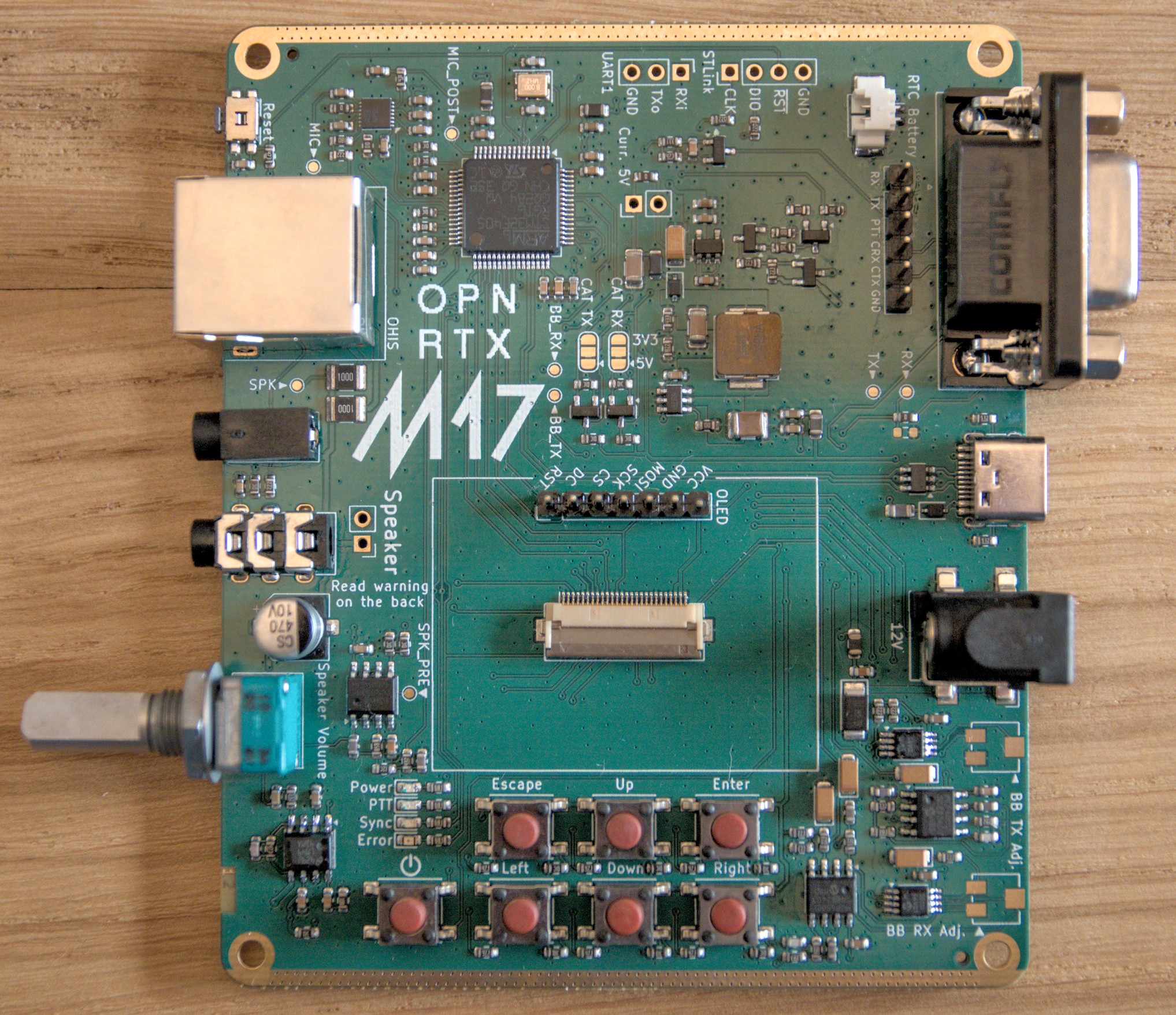
The board can be switched from one version to another relatively easily. To convert a bare board to an enclosed version, the screen needs to be removed and a few additional PCBs need to be ordered (see the Ordering guide).
You can of course always 3D-print an enclosure for your bare board.
The very first step is to get a board. The board is not available for sale yet. Head over to the Ordering guide to get a board. If you want to assemble the board with the designed enclosure and HMI, follow the instructions from the enclosure instructions.
Otherwise, if you just obtained a Module17 board, you may want to:
A list of tested transceivers is here.
Building instructions are available at the OpenRTX project's website.
The board contains many features, some of which you may never use. Here is a list:
This project is inspired by David Rowe's SM1000 "smart microphone".
Module 17 hardware is licensed under the CERN Open Hardware License - Weakly Reciprocal
Module 17 is certified by OSHWA under ID BE000019. 
| Qty | Value | Footprint | References |
|---|---|---|---|
| 23 | 100n | Capacitor_SMD:C_0603_1608Metric | C208, C209, C210, C213, C215, C216, C217, C220, C225, C226, C302, C306, C308, C309, C310, C313 +7 |
| 19 | 10k | Resistor_SMD:R_0603_1608Metric | R202, R203, R209, R210, R211, R215, R216, R219, R220, R223, R224, R305, R306, R308, R312, R317 +3 |
| 11 | 10n | Capacitor_SMD:C_0603_1608Metric | C201, C214, C219, C221, C227, C304, C315, C503, C505, C506, C508 |
| 7 | Tactile switch | Button_Switch_SMD:SW_SPST_PTS645 | SW201, SW203, SW204, SW205, SW206, SW207, SW208 |
| 6 | 470 | Resistor_SMD:R_0603_1608Metric | R217, R218, R221, R222, R229, R230 |
| 5 | 22k | Resistor_SMD:R_0603_1608Metric | R205, R206, R508, R511, R512 |
| 5 | 2k2 | Resistor_SMD:R_0603_1608Metric | R231, R232, R309, R406, R506 |
| 5 | FB0805 | Inductor_SMD:L_0805_2012Metric | FB201, FB202, FB203, FB204, FB401 |
| 4 | 100k | Resistor_SMD:R_0603_1608Metric | R201, R204, R207, R313 |
| 4 | 1u | Capacitor_SMD:C_0603_1608Metric | C211, C218, C222, C224 |
| 4 | 22u | Capacitor_Tantalum_SMD:CP_EIA-3216-18_Kemet-A | C507, C510, C511, C512 |
| 4 | 2u2 | Capacitor_SMD:C_0603_1608Metric | C204, C205, C314, C318 |
| 4 | 680 | Resistor_SMD:R_0603_1608Metric | R225, R226, R227, R228 |
| 4 | M3 | MountingHole:MountingHole_2.7mm_M2.5_DIN965_Pad | H101, H102, H103, H104 |
| 3 | 0 | Resistor_SMD:R_0603_1608Metric | R233, R311, R509 |
| 3 | 3k3 | Resistor_SMD:R_0603_1608Metric | R307, R503, R504 |
| 3 | 47k | Resistor_SMD:R_0603_1608Metric | R214, R301, R310 |
| 3 | MCP6002 | Package_SO:SOIC-8_3.9x4.9mm_P1.27mm | U301, U503, U504 |
| 2 | 100 | Resistor_SMD:R_1210_3225Metric | R409, R410 |
| 2 | 10k | Potentiometer_SMD:Potentiometer_Bourns_3224J_Horizontal | RV501, RV502 |
| 2 | 12p | Capacitor_SMD:C_0603_1608Metric | C202, C203 |
| 2 | 22 | Resistor_SMD:R_0603_1608Metric | R407, R408 |
| 2 | 22u | Capacitor_SMD:C_1206_3216Metric | C212, C223 |
| 2 | 39k | Resistor_SMD:R_0603_1608Metric | R502, R505 |
| 2 | 3k9 | Resistor_SMD:R_0603_1608Metric | R501, R507 |
| 2 | 5k1 | Resistor_SMD:R_0603_1608Metric | R401, R402 |
| 2 | 680p | Capacitor_SMD:C_0603_1608Metric | C504, C509 |
| 2 | BAT60A | Diode_SMD:D_SOD-323 | D203, D401 |
| 2 | BSS138 | Package_TO_SOT_SMD:SOT-23 | Q302, Q303 |
| 2 | MCP4551-103 | Package_SO:MSOP-8_3x3mm_P0.65mm | U501, U502 |
| 1 | +12V | Connector_BarrelJack:BarrelJack_CLIFF_FC681465S_SMT_Horizontal | J411 |
| 1 | 10k | Potentiometer_THT:Potentiometer_Alps_RK097_Single_Horizontal | RV301 |
| 1 | 10u | Capacitor_SMD:C_1210_3225Metric | C207 |
| 1 | 10u | Inductor_SMD:L_Vishay_IHLP-2525 | L201 |
| 1 | 10u | Capacitor_Tantalum_SMD:CP_EIA-3216-18_Kemet-A | C206 |
| 1 | 13k | Resistor_SMD:R_0603_1608Metric | R303 |
| 1 | 150k | Resistor_SMD:R_0603_1608Metric | R315 |
| 1 | 15p | Capacitor_SMD:C_0603_1608Metric | C307 |
| 1 | 1k | Resistor_SMD:R_0603_1608Metric | R208 |
| 1 | 1n5 | Capacitor_SMD:C_0603_1608Metric | C303 |
| 1 | 1u | Inductor_SMD:L_0805_2012Metric | L202 |
| 1 | 2.54mm Header 7p | Connector_PinHeader_2.54mm:PinHeader_1x07_P2.54mm_Vertical | J406 |
| 1 | 220n | Capacitor_SMD:C_0603_1608Metric | C305 |
| 1 | 2k | Resistor_SMD:R_0603_1608Metric | R314 |
| 1 | 330 | Resistor_SMD:R_0603_1608Metric | R302 |
| 1 | 430 | Resistor_SMD:R_0603_1608Metric | R320 |
| 1 | 43k | Resistor_SMD:R_0603_1608Metric | R213 |
| 1 | 470n | Capacitor_SMD:C_0603_1608Metric | C312 |
| 1 | 470p | Capacitor_SMD:C_0603_1608Metric | C301 |
| 1 | 470u | Capacitor_SMD:CP_Elec_6.3x7.7 | C311 |
| 1 | 4k3 | Resistor_SMD:R_0603_1608Metric | R316 |
| 1 | 7k5 | Resistor_SMD:R_0603_1608Metric | R304 |
| 1 | 8 MHz | Crystal:Crystal_SMD_3225-4Pin_3.2x2.5mm | Y201 |
| 1 | 8k2 | Resistor_SMD:R_0603_1608Metric | R212 |
| 1 | BAT54C | Package_TO_SOT_SMD:SOT-23 | D202 |
| 1 | Blue | LED_SMD:LED_0603_1608Metric | D204 |
| 1 | CAT_RX | Jumper:SolderJumper-3_P1.3mm_Bridged12_RoundedPad1.0x1.5mm | J302 |
| 1 | CAT_TX | Jumper:SolderJumper-3_P1.3mm_Bridged12_RoundedPad1.0x1.5mm | J301 |
| 1 | DNP | Resistor_SMD:R_0603_1608Metric | R510 |
| 1 | Green | LED_SMD:LED_0603_1608Metric | D206 |
| 1 | Hirose FH12-26S-0.5SH(55) | Connector_FFC-FPC:Hirose_FH12-26S-0.5SH_1x26-1MP_P0.50mm_Horizontal | J412 |
| 1 | IRLML2060 | Package_TO_SOT_SMD:SOT-23 | Q301 |
| 1 | IRLML2244 | Package_TO_SOT_SMD:SOT-23 | Q202 |
| 1 | Jumper_2_Bridged | Connector_PinHeader_2.54mm:PinHeader_1x02_P2.54mm_Vertical | JP201 |
| 1 | KH-RJ45-58-8P8C | M17_connectors:KH-RJ45-58-8P8C | J407 |
| 1 | Kenwood-2.5 | M17_connectors:PJ-211A | J405 |
| 1 | Kenwood-3.5 | M17_connectors:PJ-3136-B | J404 |
| 1 | LM4991MA | Package_SO:SOIC-8_3.9x4.9mm_P1.27mm | IC301 |
| 1 | M17_logo | M17_logos:M17_logo_20x11.5mm | LOGO101 |
| 1 | MAX9814 | Package_DFN_QFN:DFN-14-1EP_3x3mm_P0.4mm_EP1.78x2.35mm | U302 |
| 1 | MMBT3904 | Package_TO_SOT_SMD:SOT-23 | Q201 |
| 1 | Molex 532610271 | Connector_Molex:Molex_PicoBlade_53261-0271_1x02-1MP_P1.25mm_Horizontal | J413 |
| 1 | OPN_RTX_logo | M17_logos:OPN_RTX_logo_10x7.6mm | LOGO102 |
| 1 | Orange | LED_SMD:LED_0603_1608Metric | D207 |
| 1 | PTVS18VP1UP | Diode_SMD:D_SOD-128 | D201 |
| 1 | Radio | Connector_Dsub:DSUB-9_Female_Horizontal_P2.77x2.84mm_EdgePinOffset7.70mm_Housed_MountingHolesOffset9.12mm | J401 |
| 1 | Radio_Opt | Connector_PinHeader_2.54mm:PinHeader_1x06_P2.54mm_Vertical | J403 |
| 1 | Red | LED_SMD:LED_0603_1608Metric | D205 |
| 1 | STLink | Connector_PinHeader_2.54mm:PinHeader_1x04_P2.54mm_Vertical | J408 |
| 1 | STM32F405RGTx | Package_QFP:LQFP-64_10x10mm_P0.5mm | U201 |
The 191 most common of 209 parts.
It measures 100 × 83 mm and has 4 copper layers, 1.61 mm thick.
209 parts, built around the STM32F405RGT6V, MCP6002-I/SN, LM4991MA and MAX9814ETD+T. The full list of its parts is on this page, with links to each part's symbol and footprint where PCBKit's library has them.
From the M17-Project/Module_17 repository on GitHub, at the commit this page was made from: the board is hardware/mainboard/Module17-Mainboard.kicad_pcb and its schematic hardware/HMI/Module17-HMI.kicad_sch. PCBKit opens the board in the browser, with nothing to install.
Its repository publishes it under the CERN-OHL-W-2.0 licence: you may reuse it on that licence's terms (keep the author's notice, and for a copyleft licence share your changes alike).
M17-Project/Module_17
M17 modem board for 9600-baud capable radios


james10952001/FPGA-mini-vector-arcade
Vector game daughter board for the Altera EP2C5T144 Cyclone II "mini board"


SmallCoral/Coral-Wave
SAMD21E18A + WM8978 USB sound card with stereo headphone playback and microphone capture. KiCad hardware and firmware.


embeddedos-org/eCAD-Hardware-Products
Hardware designs + EE docs + Board datasheets of Multiple products

steveed/a1200kb-external-case
Some ideas for using an external Amiga keyboard with an A1200 in a desktop or tower case.