4 layers154 × 154 mm
DC Controller STM32
andymartell/Prius-STM32-DC-Motor-Contoller
STM32 based DC Motor Controller using Prius Gen 3 hardware
293 parts

 metalhead777/blinCAN
A 24 channel LED driver with CAN bus interface and Arduino-style microcontroller.
BlinCAN is an open-source printed circuit board by metalhead777, from the metalhead777/blinCAN repository on GitHub, published under the CC-BY-SA-4.0 licence. It is a 2-layer board of 127.1 × 67.1 mm with 103 parts on 107 nets, routed with 743 tracks and 73 vias.
It is built around the ATMEGA328P-AU, MCP2551-I/SN and FT232RQ, with the LM35DZ, TLC5947DAP and MCP2515-I/SO among its other parts. Its parts include 25 capacitors, 21 resistors, 17 diodes, 9 connectors and 7 ICs. It belongs with the interfaces and adapters boards and the AVR (ATmega, ATtiny) boards of this library.


A 24 channel LED driver module with CAN bus interface and Arduino-compatible microcontroller.
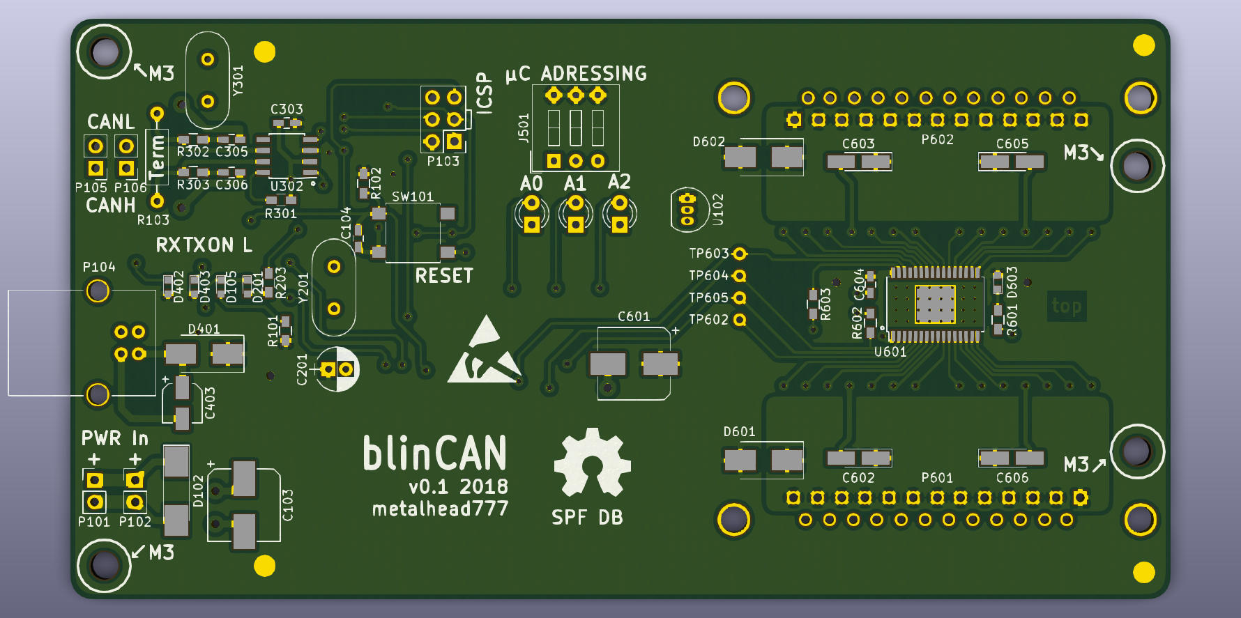 blinCAN v0.1 2018 top
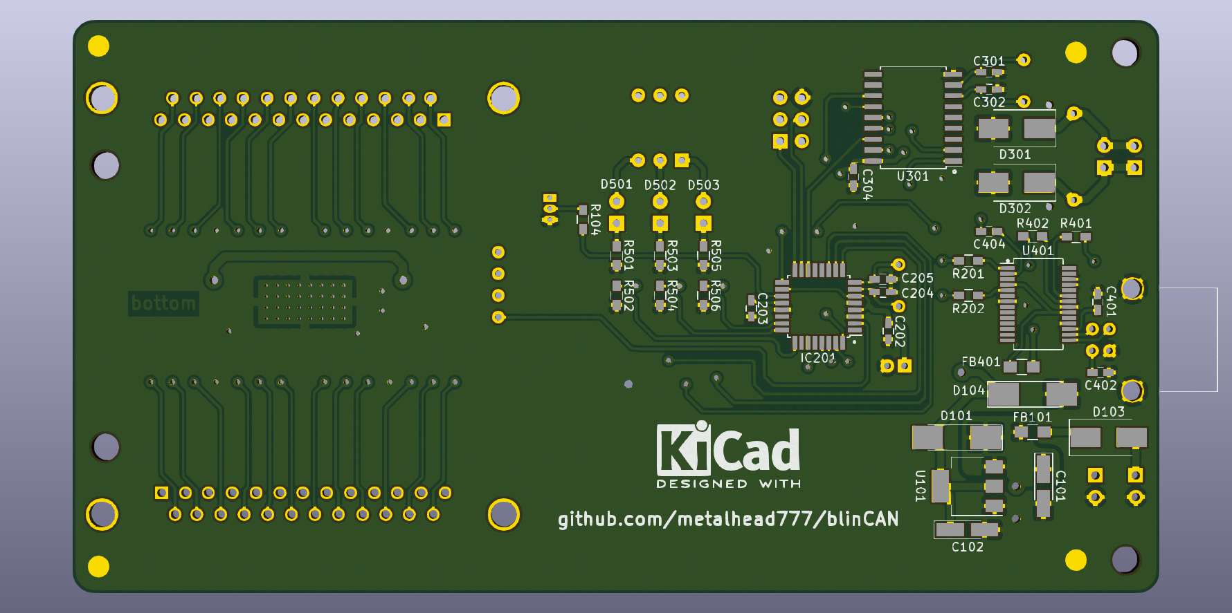 blinCAN v0.1 2018 bottom
The blinCAN is based on a multi-channel power LED driver module developed for the Desert Eyes project. It is matched to a small-scale construction prototype dome, which served to test construction and lighting patterns for the full-scale dome.
This module is built around a TLC5947 PWM LED driver IC, which is connected to an ATmega328 microcontroller. For communication, a MCP2551 CAN transceiver and a MCP2515 CAN controller with SPI interface to the microcontroller are utilized. A FT232R USB to UART interface has been added to allow programming via USB, once a bootloader is flashed onto the microcontroller. For ambient air temperature sensing, a LM35 temperature sensor has been placed near the LED driver IC. A DIP switch is used to set a hardware-level address on each device, which also gets indicated by corresponding LEDs. For easier connection of an already wired LED harness, 25-pin SUB-D connectors are used on the output.
On the small-scale construction prototype dome, a Raspberry Pi with a CAN bus HAT was used as a host to centrally generate and send lighting patterns to six blinCAN modules via the CAN bus. Each blinCAN module had a unique address within the CAN bus, and every LED on the dome was purposely connected to a predefined module output. This way, every LED on the dome's shell was distinctly addressable in 3D space. An underlying look-up-table in the host's software was used to map each pattern lighting point to an LED.
Currently the blinCAN is in early development state in version 0.1. This means, that the hardware is tested and working on a small prototype scale production. Long-term testing (temperature, vibration, EMI) has not been performed yet. In this state the blinCAN is fit to be used for embedded systems and small-scale lighting projects. Any large-scale production is not encouraged, since additional optimization in the hardware layout needs to be done for that.
A few prototypes have been built and successfully tested prior to releasing this repository.
After assembly, the device can only be programmed using an ICSP in-circuit-programmer. The connector with the reference P103 serves as ICSP header. The square pad is ICSP Pin 1 (MISO).
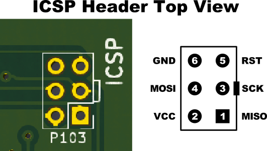
P103 ICSP header pin connection
The blinCAN firmware can be flashed directly to the ATmega328P-AU using an In-Series Programmer (ISP). The reset-button needs to be pressed during microcontroller flashing
For editing the blinCAN firmware or testing any other Arduino-compatible code, the Arduino bootlader needs to be flashed first to the ATmega328P-AU used for the blinCAN. A tutorial on flashing the Arduino bootloader can be found here. Use the following settings under "Tools" in the Arduino IDE, if you use another Arduino as a flashing device (ISP):
| Parameter | Value |
|---|---|
| Board | "Arduino Nano" |
| Processor | "ATmega328P" |
After flashing the Arduino bootloader, any further programming can be done using the USB type B connector (P104) on the blinCAN.
This project is open source and licensed under Creative Commons Attribution Share Alike 4.0.
Please refer to License.md for the full legal text. Thanks to idleberg on GitHub for the Markdown format.
The project is distributed as-is. No warranty is given.
| Qty | Value | Footprint | References |
|---|---|---|---|
| 9 | 100N | Capacitors_SMD:C_0603_HandSoldering | C104, C202, C203, C303, C304, C401, C402, C404, C604 |
| 6 | Tantal 10u/16V | Capacitors_Tantalum_SMD:CP_Tantalum_Case-A_EIA-3216-18_Hand | C101, C102, C602, C603, C605, C606 |
| 4 | 1k | Resistors_SMD:R_0603_HandSoldering | R102, R104, R201, R202 |
| 4 | 22P | Capacitors_SMD:C_0603_HandSoldering | C204, C205, C301, C302 |
| 4 | 330 | Resistors_SMD:R_0603_HandSoldering | R101, R203, R401, R402 |
| 4 | MBRS 240 SMD | Diodes_SMD:D_SMB_Handsoldering | D103, D401, D601, D602 |
| 3 | 10k | Resistors_SMD:R_0603_HandSoldering | R502, R504, R506 |
| 3 | 130 | Resistors_SMD:R_0603_HandSoldering | R501, R503, R505 |
| 3 | 1N 4001 SMD | Diodes_SMD:D_MELF_Handsoldering | D101, D102, D104 |
| 3 | LED Orange | LEDs:LED_D3.0mm | D501, D502, D503 |
| 2 | 100 | Resistors_SMD:R_0603_HandSoldering | R302, R303 |
| 2 | 16 MHz | Crystals:Crystal_HC49-U_Vertical | Y201, Y301 |
| 2 | 560p | Capacitors_SMD:C_0603_HandSoldering | C305, C306 |
| 2 | Conn_CAN | Pin_Headers:Pin_Header_Straight_1x02_Pitch2.54mm | P105, P106 |
| 2 | Conn_PWR_IN | Pin_Headers:Pin_Header_Straight_1x02_Pitch2.54mm | P101, P102 |
| 2 | D-SUB 25 | DB25FC:DB25FC | P601, P602 |
| 2 | EMI suppression Filter 30 Ohms | Inductors_SMD:L_0805_HandSoldering | FB101, FB401 |
| 2 | LED Green | LEDs:LED_0603 | D403, D603 |
| 2 | P6SMB 27A SMD | Diodes_SMD:D_SMB_Handsoldering | D301, D302 |
| 1 | 10K | Resistors_SMD:R_0603_HandSoldering | R602 |
| 1 | 120 | Resistors_THT:R_Axial_DIN0207_L6.3mm_D2.5mm_P10.16mm_Horizontal | R103 |
| 1 | 330u/16V | Capacitors_SMD:CP_Elec_8x10.5 | C601 |
| 1 | 330u/25V | Capacitors_SMD:CP_Elec_8x10.5 | C103 |
| 1 | 3K3 | Resistors_SMD:R_0603_HandSoldering | R603 |
| 1 | 4.7u/16V | Capacitors_SMD:CP_Elec_4x5.7 | C403 |
| 1 | 4.7u/16V | Capacitors_THT:CP_Radial_D5.0mm_P2.00mm | C201 |
| 1 | 470 | Resistors_SMD:R_0603_HandSoldering | R601 |
| 1 | 4k7 | Resistors_SMD:R_0603_HandSoldering | R301 |
| 1 | ATMEGA328P-AU | Housings_QFP:TQFP-32_7x7mm_Pitch0.8mm | IC201 |
| 1 | CONN_ICSP | Pin_Headers:Pin_Header_Straight_2x03_Pitch2.54mm | P103 |
| 1 | Conn_Address | Buttons_Switches_THT:SW_DIP_x3_W7.62mm_Slide | J501 |
| 1 | FT232R | Housings_SSOP:SSOP-28_5.3x10.2mm_Pitch0.65mm | U401 |
| 1 | LD1117S50TR_SOT223 | TO_SOT_Packages_SMD:SOT-223-3_TabPin2 | U101 |
| 1 | LED Blue | LEDs:LED_0603 | D105 |
| 1 | LED Orange | LEDs:LED_0603 | D201 |
| 1 | LED Red | LEDs:LED_0603 | D402 |
| 1 | LM35DZ | TO_SOT_Packages_THT:TO-92_Inline_Narrow_Oval | U102 |
| 1 | MCP2515-I/SO | Housings_SOIC:SOIC-18W_7.5x11.6mm_Pitch1.27mm | U301 |
| 1 | MCP2551-I/SN | Housings_SOIC:SOIC-8_3.9x4.9mm_Pitch1.27mm | U302 |
| 1 | Reset | Buttons_Switches_SMD:SW_SPST_B3S-1000 | SW101 |
| 1 | TEST_CLK | Measurement_Points:Measurement_Point_Round-TH_Small | TP605 |
| 1 | TEST_DIN | Measurement_Points:Measurement_Point_Round-TH_Small | TP602 |
| 1 | TEST_LAT | Measurement_Points:Measurement_Point_Round-TH_Small | TP603 |
| 1 | TEST_OE | Measurement_Points:Measurement_Point_Round-TH_Small | TP604 |
| 1 | TLC5947 | Housings_SSOP:HTSSOP-32_6.1x11mm_Pitch0.65mm_ThermalPad | U601 |
| 1 | USB B | Connectors:USB_B | P104 |
The 88 most common of 103 parts.
andymartell/Prius-STM32-DC-Motor-Contoller
STM32 based DC Motor Controller using Prius Gen 3 hardware


MadsRudolph/personal-projects
One passive crossover board per speaker, so build two. Single-sided, through-hole only, CNC isolation-milled with an 0.8 mm end mill (the DTU 62768 process).


franc0r/universal_can_board
Contains schematic, pcb layout and software of the francor's universal can board.


It measures 127.1 × 67.1 mm and has 2 copper layers, 1.6 mm thick.
103 parts, built around the ATMEGA328P-AU, MCP2551-I/SN, FT232RQ and LM35DZ. The full list of its parts is on this page, with links to each part's symbol and footprint where PCBKit's library has them.
From the metalhead777/blinCAN repository on GitHub, at the commit this page was made from: the board is blinCAN.kicad_pcb. PCBKit opens the board in the browser, with nothing to install.
Its repository publishes it under the CC-BY-SA-4.0 licence: you may reuse it on that licence's terms (keep the author's notice, and for a copyleft licence share your changes alike).