2 layers30.5 × 62.2 mm

 mcubelab/gelslim114
LED Driver is an open-source printed circuit board by mcubelab, from the mcubelab/gelslim repository on GitHub. It is a 2-layer board of 35.3 × 26.7 mm with 8 parts on 13 nets, routed with 85 tracks and 0 vias.
It is built around the 10118193-0001LF, CRCW25120000Z0EG and ERJ-1TNF14R3U, with the ERJ-1TNF43R2U and ERJ-1TNF88R7U among its other parts.


Note: The MCube Lab at MIT has closed and no longer distributes pre-made sensors by mail upon request. Consider the latest version GelSlim 4.0 at the University of Michigan's MMint Lab for an easier to reproduce version of the sensor.
Please follow the Hardware Quick Start Guide instructions to build your own sensor. The step-by-step resources found below are in the process of being updated.
Click on the pictures below for more information
| 3-D Printing | PCB Fabrication | Elastomer Fabrication | Assembly |
|---|---|---|---|
| [Image blocked: No description] | 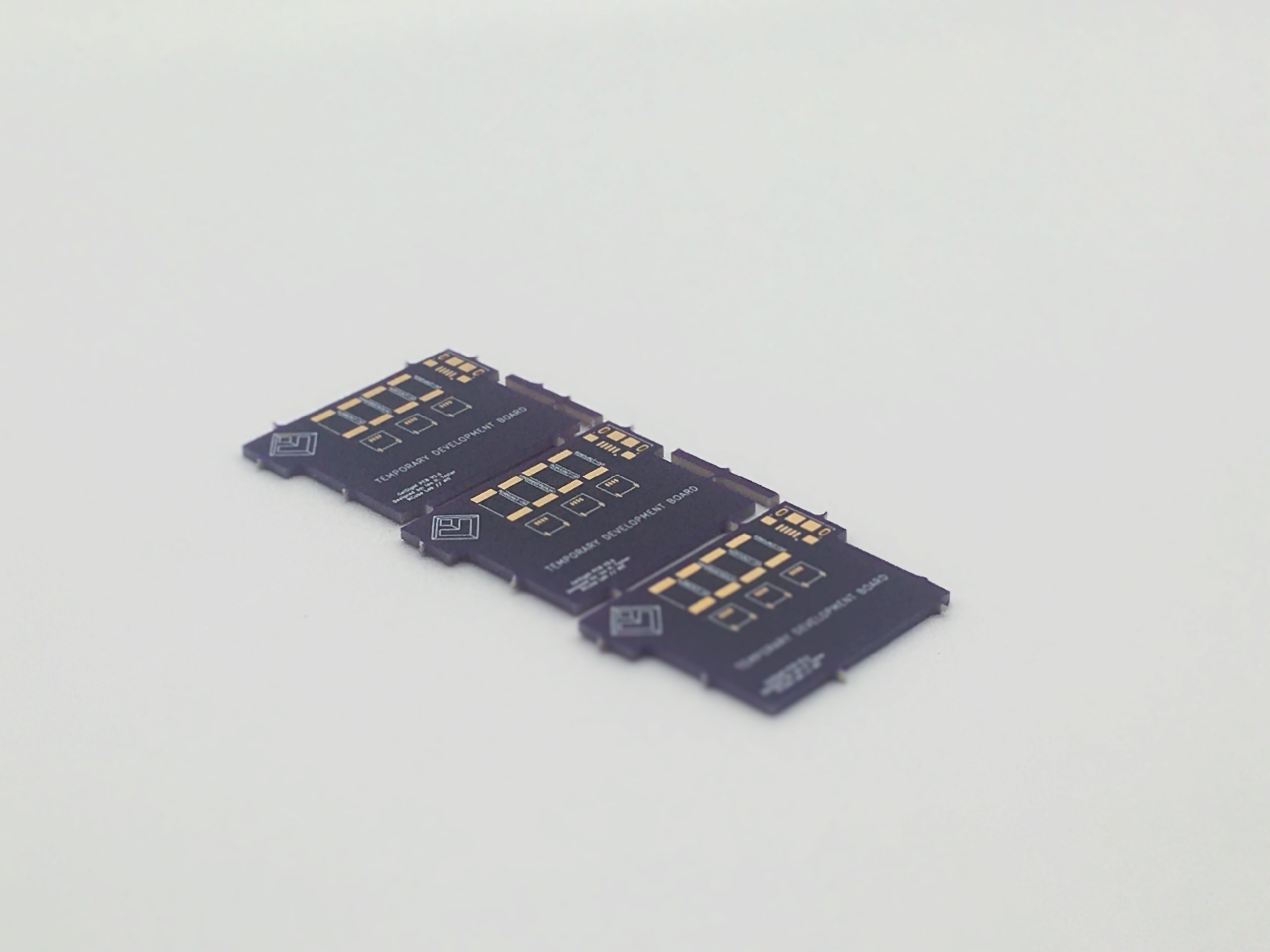 | 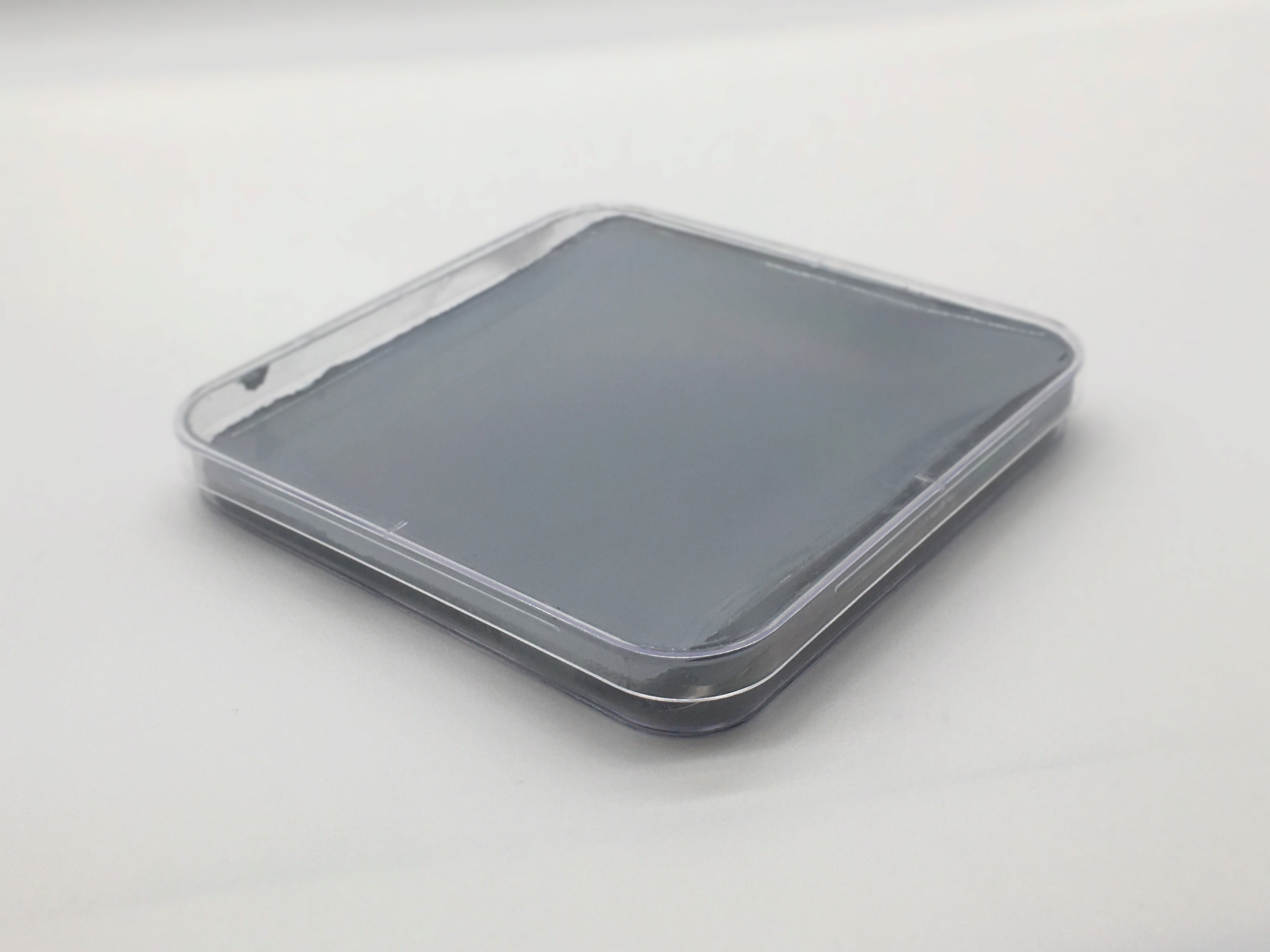 | 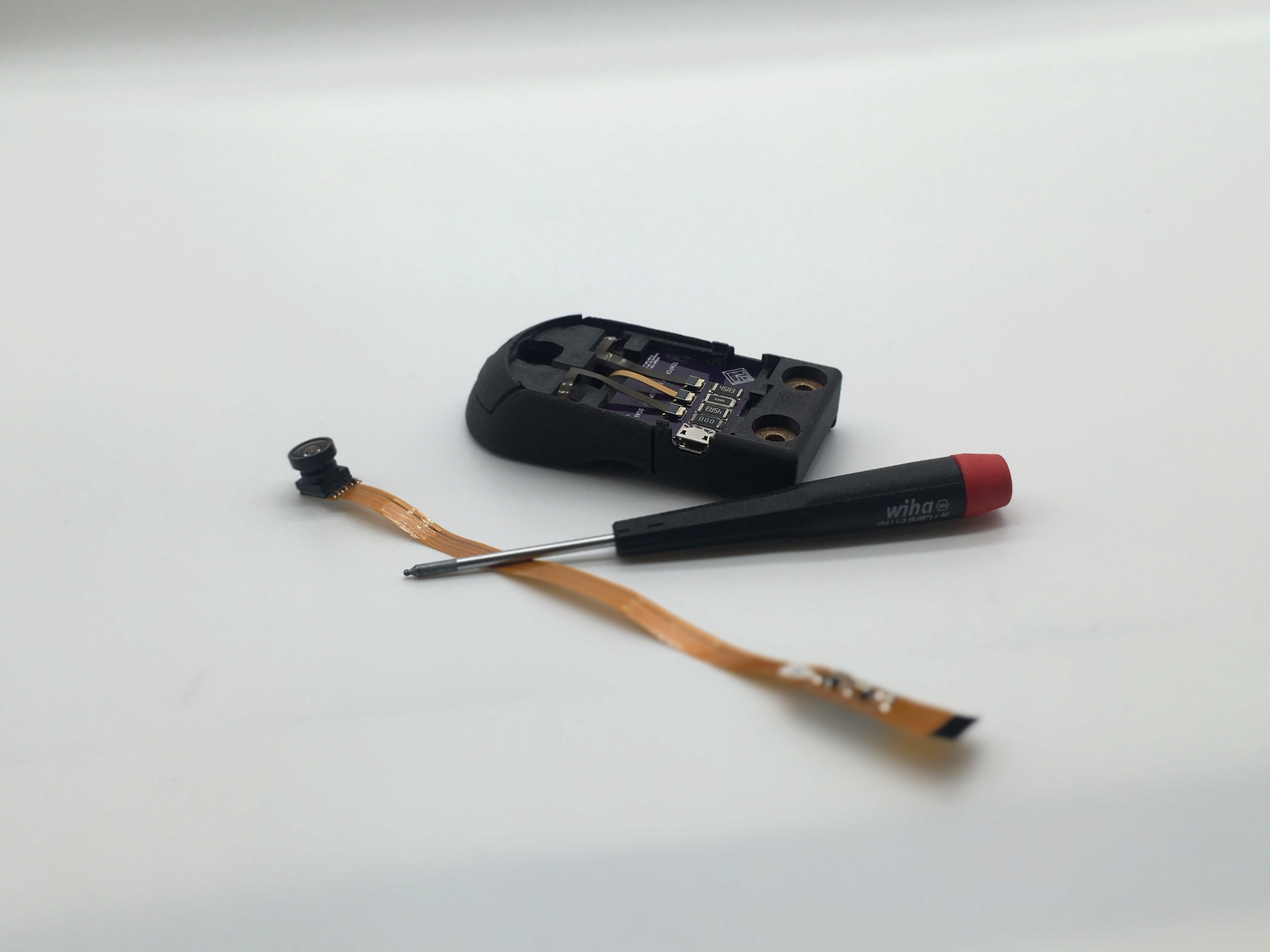 |
| Elastomer | Fasteners | Body | Shaping Lens |
|---|---|---|---|
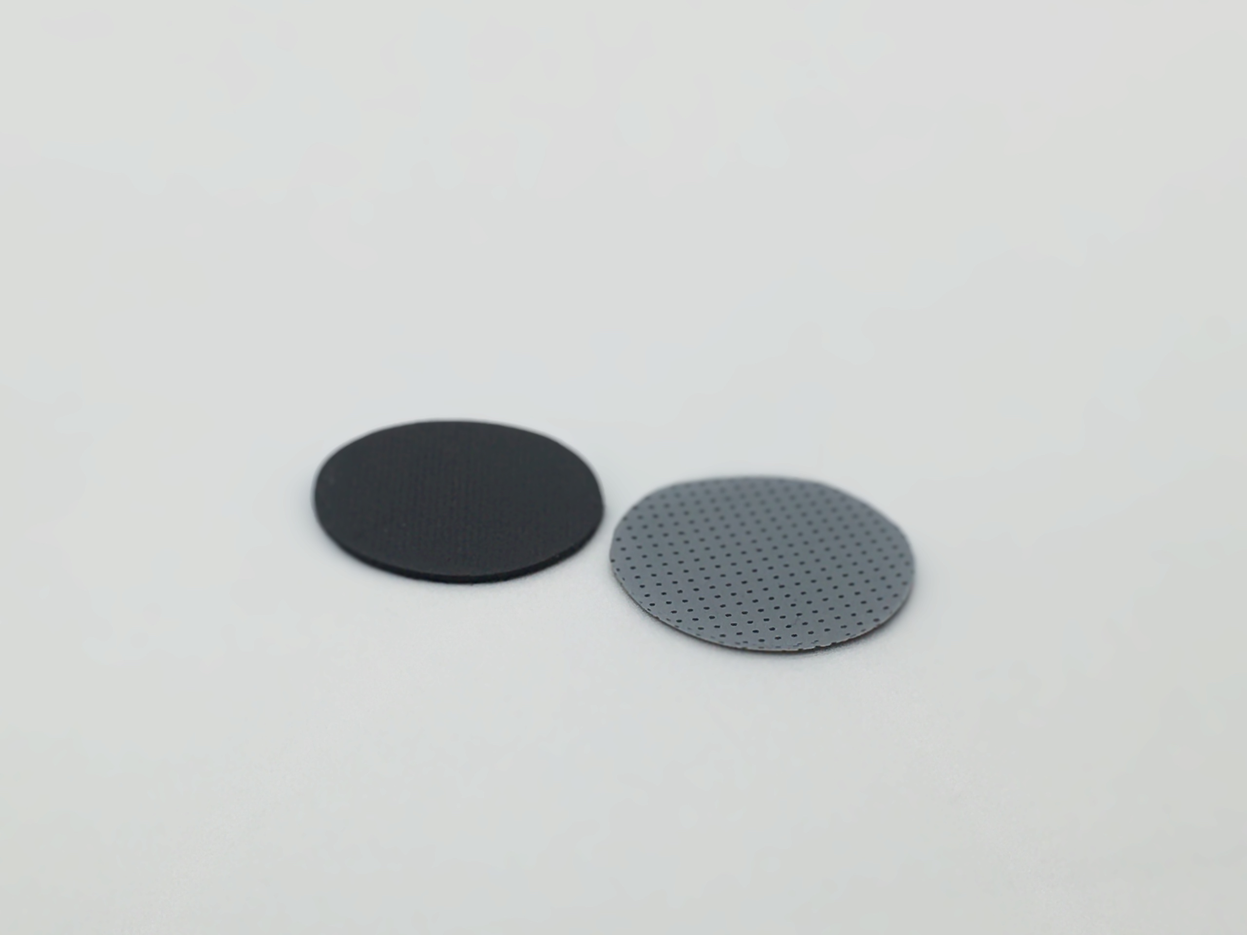 | 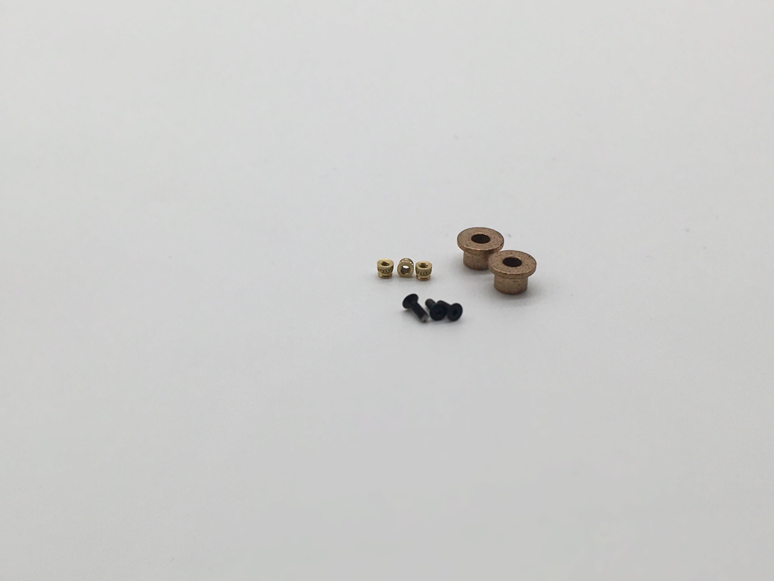 | 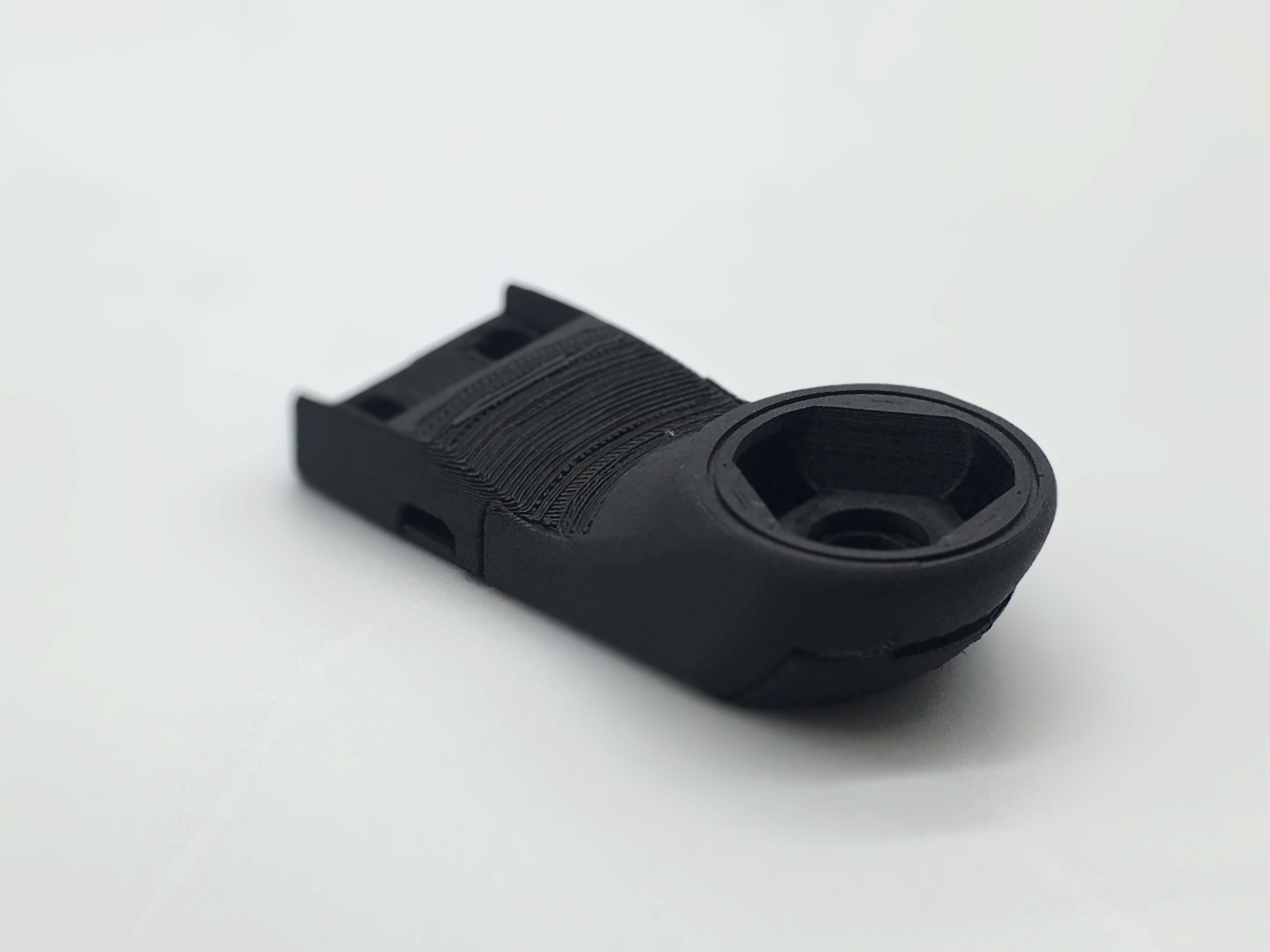 | 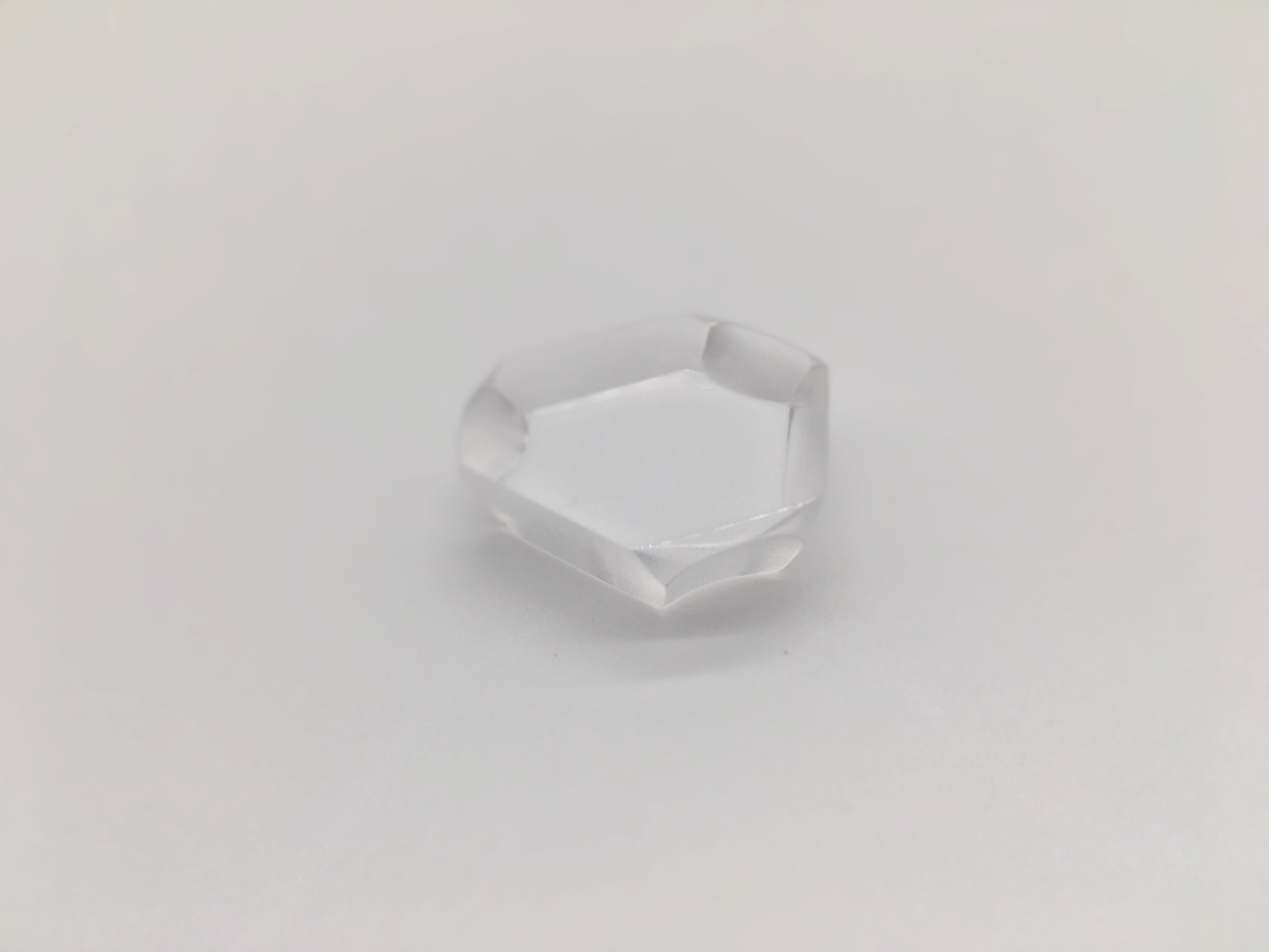 |
| LED Driver | LED Harness | Camera | Connectors and Adapters |
|---|---|---|---|
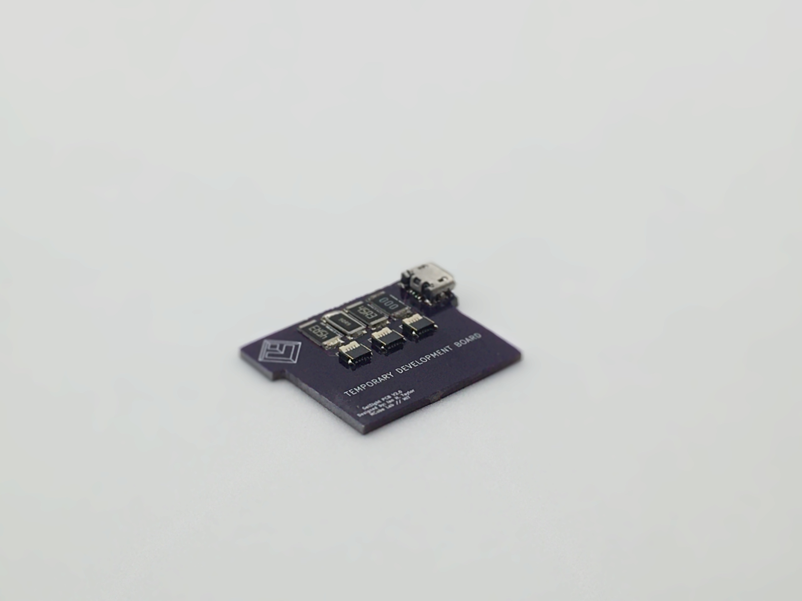 | 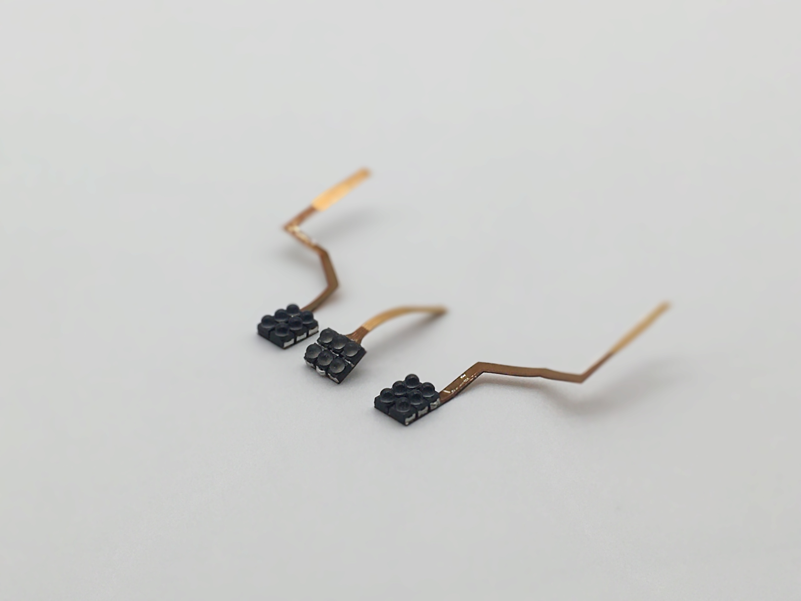 | 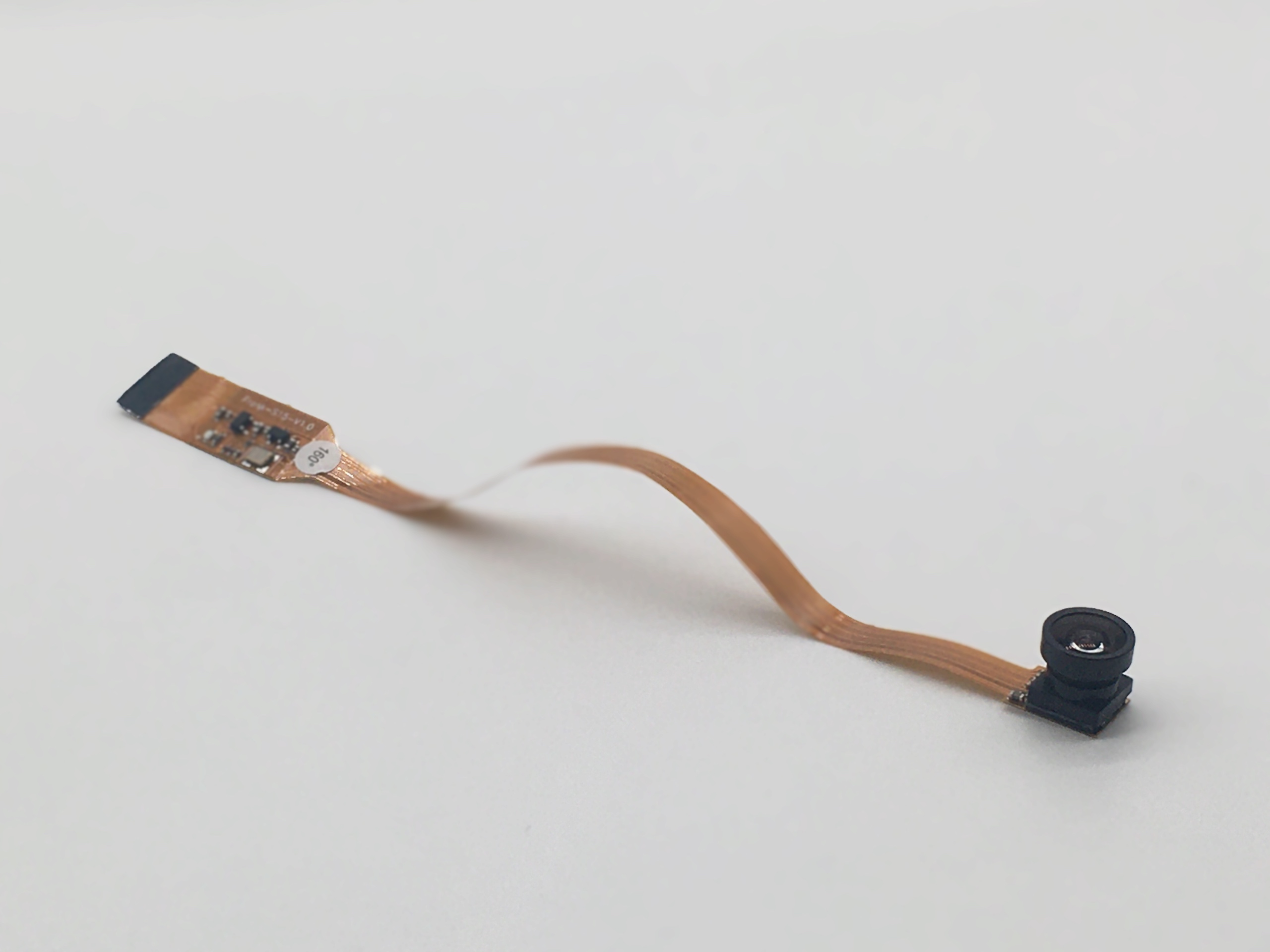 | 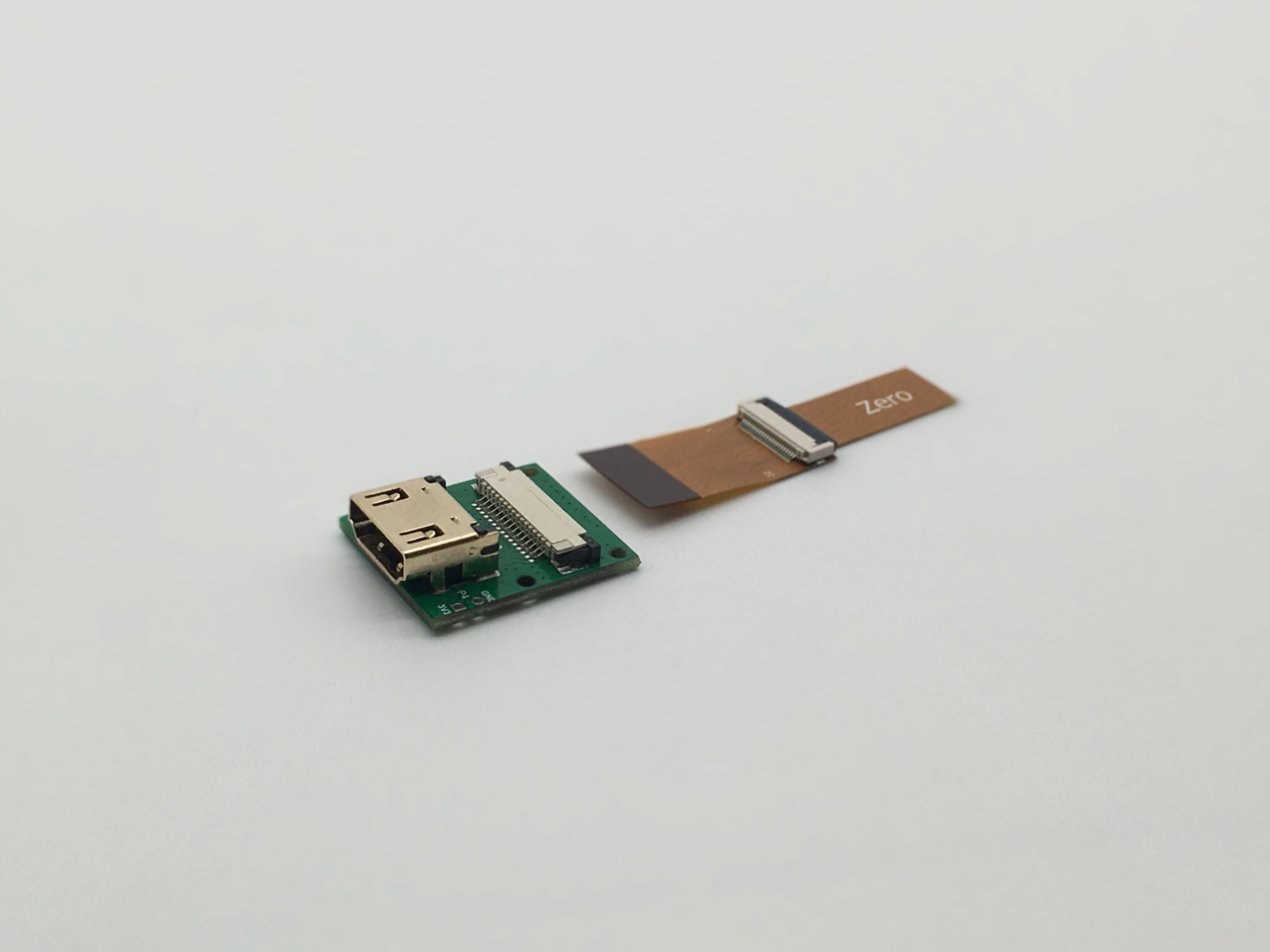 |
| Raspberry Pi | Dependencies | GUI | Calibration |
|---|---|---|---|
 |  |  |  |
| Mechanical Tools and Consumables | Electronics Components and Tools | Known Issues | Contributing |
|---|---|---|---|
 |  |  |  |
GelSlim 3.0 - Webpage
GelSlim 3.0 - Paper
GelSlim 3.0 - Demo
MCube Lab - YouTube Channel
This repo is under construction, the following files and folders are not present.
Ian Taylor
These design files are licensed under CC-by-NC, as found in the LICENSE file.
| Qty | Value | Footprint | References |
|---|---|---|---|
| 1 | 10118193-0001LF | FCI_10118193-0001LF | |
| 1 | BLUE | 503480-0400:MOLEX_503480-0400 | |
| 1 | CRCW25120000Z0EG | CRCW25120000Z0EG:RESC6331X70N | |
| 1 | ERJ-1TNF14R3U | ERJ-1TNF14R3U:RESC6432X70N | |
| 1 | ERJ-1TNF43R2U | ERJ-1TNF43R2U:RESC6432X70N | |
| 1 | ERJ-1TNF88R7U | ERJ-1TNF88R7U:RESC6432X70N | |
| 1 | GREEN | 503480-0400:MOLEX_503480-0400 | |
| 1 | RED | 503480-0400:MOLEX_503480-0400 |


ShawnHymel/rpi-pico-debugger-shoe
Stackable debugger board for the Raspberry Pi Pico. Solder long headers to this debugger board in order to connect the Pico to it.

ranzbak/qmtech_minimig
KiCad design for a minimig compatible board for the QM_XC7A100T_DDR3 board.


uw-x/clearbuds-hw
Errata: The design contains some errors that can be addressed in future revisions. The errors do not affect function, but do affect robustness. 1. Add 0.1uF decoupling capacitor to PDM mic (ICS-41350) Vcc. 2.

rishivg/IO-SDR
Open-Source software-defined FPGA radio hardware platform

RocketryVT/active-drag-system
Eigen Library, cmake, and arm-none-eabi-gcc tooling required for successful build.
It measures 35.3 × 26.7 mm and has 2 copper layers, 1.6 mm thick.
8 parts, built around the 10118193-0001LF, CRCW25120000Z0EG, ERJ-1TNF14R3U and ERJ-1TNF43R2U. The full list of its parts is on this page, with links to each part's symbol and footprint where PCBKit's library has them.
From the mcubelab/gelslim repository on GitHub, at the commit this page was made from: the board is Hardware/Electrical/LED Driver/LED Driver.kicad_pcb. PCBKit opens the board in the browser, with nothing to install.
Its repository states no licence, so its author keeps all rights: ask mcubelab before reusing the design.