4 layers130 × 110 mm

 MaloufSleep/ME-ESP8266204
Malouf Electronics - ESP8266 Dev Board
ESP8266 is an open-source printed circuit board by MaloufSleep, from the MaloufSleep/ME-ESP8266 repository on GitHub, published under the MIT licence. It is a 2-layer board of 66.8 × 34 mm with 127 parts on 78 nets, routed with 500 tracks and 47 vias.
It is built around the CH340C, ESP8266EX and MAX232ESE+T, with the W25Q128JVSIQ, CC0603KRX7R9BB104 and AO3400A among its other parts. Its parts include 26 resistors, 19 capacitors, 6 ICs, 6 transistors and 5 diodes. It belongs with the microcontroller boards boards and the ESP8266 boards of this library.


Malouf Electronics - ESP8266 Dev Board
The ultimate ESP8266 development board built by makers for makers.

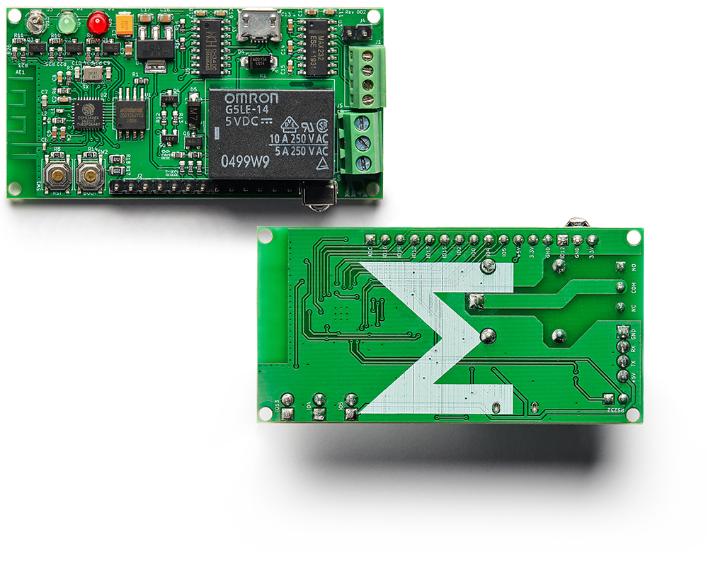
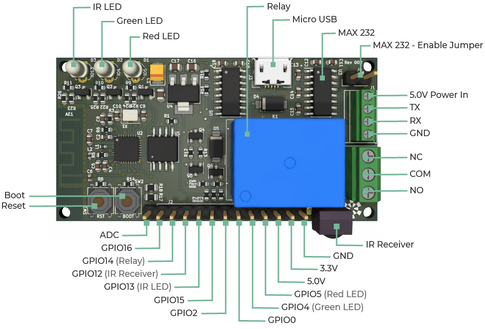
const int LED_RED = 5;

void setup() {
    pinMode(LED_RED, OUTPUT);     // setup red LED as output
}

void loop() {

    digitalWrite(LED_RED, LOW);   // turn the LED on
    delay(1000);                  // wait for a second

    digitalWrite(LED_RED, HIGH);  // turn the LED off
    delay(1000);                  // wait for a second

}
If all goes well the board will program and the red LED will start blinking.
| Qty | Value | Footprint | References |
|---|---|---|---|
| 11 | 0603WAF1002T5E | Resistor_SMD:R_0603_1608Metric | R2, R4, R5, R6, R7, R12, R13, R20, R24, R25, R26 |
| 8 | 0603WAF4700T5E | Resistor_SMD:R_0603_1608Metric | R8, R14, R15, R16, R19, R21, R22, R23 |
| 6 | CL10A105KB8NNNC | Capacitor_SMD:C_0603_1608Metric | C4, C5, C12, C13, C14, C15 |
| 5 | CC0603KRX7R9BB104 | Capacitor_SMD:C_0603_1608Metric | C2, C8, C11, C18, C19 |
| 4 | AO3400A | Package_TO_SOT_SMD:SOT-23 | Q1, Q2, Q3, Q6 |
| 3 | 0603WAF620JT5E | Resistor_SMD:R_0603_1608Metric | R9, R10, R11 |
| 3 | CL21A106KAYNNNE | Capacitor_SMD:C_0805_2012Metric | C3, C16, C17 |
| 2 | 0603CG6R8C500NT | Capacitor_SMD:C_0603_1608Metric | C9, C10 |
| 2 | S8050_SMD | Package_TO_SOT_SMD:SOT-23 | Q4, Q5 |
| 2 | TS-1187A-B-A-B | Button_Switch_SMD:TS-1187A-B-A-B | SW1, SW2 |
| 1 | 0402CG2R7C500NT | Capacitor_SMD:C_0402_1005Metric | C6 |
| 1 | 0603CG3R0C500NT | Capacitor_SMD:C_0603_1608Metric | C7 |
| 1 | 0603WAF1202T5E | Resistor_SMD:R_0603_1608Metric | R3 |
| 1 | 0603WAF2000T5E | Resistor_SMD:R_0603_1608Metric | R1 |
| 1 | 0805W8F2203T5E | Resistor_SMD:R_0805_2012Metric | R17 |
| 1 | 0805W8F8202T5E | Resistor_SMD:R_0805_2012Metric | R18 |
| 1 | 10118193-0001LF | digikey-footprints:USB_Micro_B_Female_10118193-0001LF | J3 |
| 1 | 282834-4 | TerminalBlock_TE-Connectivity:TerminalBlock_TE_282834-4_1x04_P2.54mm_Horizontal | J1 |
| 1 | 284391-3 | TerminalBlock_TE-Connectivity:TE_284391-3 | J5 |
| 1 | 68000-102HLF | Connector_PinHeader_2.54mm:PinHeader_1x02_P2.54mm_Vertical | J4 |
| 1 | 68000-113HLF | Connector_PinHeader_2.54mm:PinHeader_1x13_P2.54mm_Vertical | J2 |
| 1 | Antenna_Shield | RF_Antenna:Texas_SWRA117D_2.4GHz_Right | AE1 |
| 1 | CH340C | Package_SO:SOIC-16_3.9x9.9mm_P1.27mm | U5 |
| 1 | ESP8266EX | Package_DFN_QFN:QFN-32-1EP_5x5mm_P0.5mm_EP3.45x3.45mm_ThermalVias | U2 |
| 1 | G5LE-1 | Relay_THT:Relay_SPDT_Omron-G5LE-1 | K1 |
| 1 | GF1A | digikey-footprints:DO-214AC | D5 |
| 1 | LOGO | Images:M_Electronics | G*** |
| 1 | LOGO | Images:Dijarik | G*** |
| 1 | LQG15HS2N2S02D | Inductor_SMD:L_0402_1005Metric | L2 |
| 1 | MAX232ESE+T | Package_SO:SOIC-16_3.9x9.9mm_P1.27mm | U3 |
| 1 | NCP1117-3.3_SOT223 | Package_TO_SOT_SMD:SOT-223-3_TabPin2 | U4 |
| 1 | QBL7IG60D | digikey-footprints:LED_3mm_Radial | D2 |
| 1 | QBL7SA60D | digikey-footprints:LED_3mm_Radial | D1 |
| 1 | SDCL1005C4N3STDF | Inductor_SMD:L_0402_1005Metric | L1 |
| 1 | SS14 | digikey-footprints:DO-214AC | D4 |
| 1 | TAJB107K006RNJ | Capacitor_Tantalum_SMD:CP_EIA-3528-15_AVX-H | C1 |
| 1 | TSHA440 | digikey-footprints:LED_3mm_Radial | D3 |
| 1 | VS1838B | OptoDevice:Vishay_MOLD-3Pin | U6 |
| 1 | W25Q128JVSIQ | Package_SO:SO-8_5.3x6.2mm_P1.27mm | U1 |
| 1 | X1E000021081900 | Crystal:Crystal_SMD_3225-4Pin_3.2x2.5mm | X1 |
The 76 most common of 127 parts.

anhenaobe/nrf52840-modular-wireless-som
Reusable four-layer nRF52840 wireless SoM with BLE, USB-C, LiPo charging, buck-boost power management, RF antenna integration, and manufacturing-ready outputs.

ivarhak/BlueprintFlightComputerPCB
Files for my flight computer project as a part of the Hack Club foundation's Blueprint program 2025. Board has an STM chip, 2 BMP351 barometers, 1 ICM-42688-P IMU, a microSD slot, battery charging capabilities, and…

PubInv/krake
The Krake™ is a Wi-Fi–enabled server using an MQTT broker, which means it can be controlled remotely by other devices ("clients") via the internet.

PubInv/general-purpose-alarm-device
A general purpose alarm device (with software) as a module for medical devices (and others)


ngrabbs/ember
Open pvpanel.kicadpro with KiCad 10. The project contains the recovered schematic, routed PCB, project-local footprint libraries, and solar-module STEP model.

ab3nd/TinyRobo
Hardware and software for a tiny robot platform based on the ESP-8266 WiFi modules and hacked children's toys.
It measures 66.8 × 34 mm and has 2 copper layers, 1.6 mm thick.
127 parts, built around the CH340C, ESP8266EX, MAX232ESE+T and W25Q128JVSIQ. The full list of its parts is on this page, with links to each part's symbol and footprint where PCBKit's library has them.
From the MaloufSleep/ME-ESP8266 repository on GitHub, at the commit this page was made from: the board is ESP8266.kicad_pcb. PCBKit opens the board in the browser, with nothing to install.
Its repository publishes it under the MIT licence: you may reuse it on that licence's terms (keep the author's notice, and for a copyleft licence share your changes alike).