2 layers

 ranzbak/qmtech_minimig24
KiCad design for a minimig compatible board for the QM_XC7A100T_DDR3 board.
Qmtech minimig is an open-source printed circuit board by ranzbak, from the ranzbak/qmtech_minimig repository on GitHub. It is a 4-layer board of 142.3 × 105.7 mm with 222 parts on 292 nets, routed with 14,165 tracks and 316 vias.
It is built around the MT3608, TPD12S520DBTR and SCHA5B0200, with the ADV7511KSTZ, AS4C16M16SA-6TCNTR and MCP23S17-E/SO among its other parts. Its parts include 67 capacitors, 67 resistors, 17 diodes, 12 ICs and 11 connectors. It belongs with the ESP32 boards of this library.


This PCB has been designed for my project in order to run the Minimig Amiga core on a board of my own design. The core FPGA board I bought of Aliexpress, because soldering the very fine pitched BGA socket is too cumbersome.
More detailed documents regarding the I/O board can be found in the docs directory in this repository.
The board as is works, the features have been tested individually, but I'm still working on the Minimig port at this time. Since I work on this in my spare time progress is not super fast, but progress is made. For now I'm mostly learning and developing at the same time so a lot of stuff changes. When the code base becomes more stable and usable I'll open the repository up.
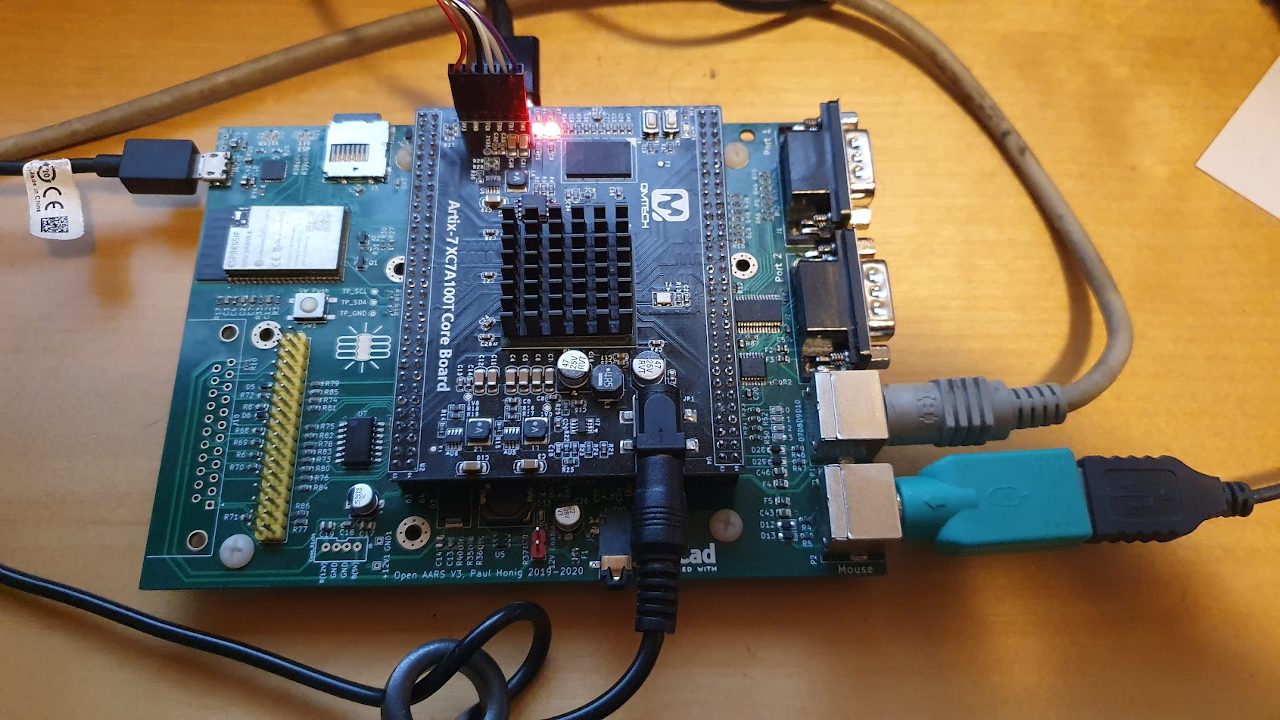
Firmware for the Amiga works!
Keep in mind I'm only planning on making an Amiga core for this board, but feel free to contribute other cores.
** Make sure to ask the seller to ship the board without the female headers soldered on, for the Open AARS board male headers are needed. **
THE PROJECT IS PROVIDED "AS IS", WITHOUT WARRANTY OF ANY KIND, EXPRESS OR IMPLIED, INCLUDING BUT NOT LIMITED TO THE WARRANTIES OF MERCHANTABILITY, FITNESS FOR A PARTICULAR PURPOSE AND NONINFRINGEMENT. IN NO EVENT SHALL THE AUTHORS OR COPYRIGHT HOLDERS BE LIABLE FOR ANY CLAIM, DAMAGES OR OTHER LIABILITY, WHETHER IN AN ACTION OF CONTRACT, TORT OR OTHERWISE, ARISING FROM, OUT OF OR IN CONNECTION WITH THE PROJECT OR THE USE OR OTHER DEALINGS IN THE PROJECT.
| Qty | Value | Footprint | References |
|---|---|---|---|
| 36 | 100nF | Capacitor_SMD:C_0603_1608Metric | C1, C2, C3, C10, C11, C12, C13, C16, C18, C20, C24, C25, C32, C33, C34, C35 +20 |
| 18 | 10k | Resistor_SMD:R_0603_1608Metric | R2, R7, R12, R20, R21, R22, R23, R24, R27, R30, R31, R34, R37, R56, R60, R62 +2 |
| 13 | 1k | Resistor_SMD:R_0603_1608Metric | R6, R8, R10, R25, R26, R38, R39, R65, R68, R69, R70, R71, R72 |
| 10 | 10uF | Capacitor_SMD:C_0805_2012Metric | C21, C22, C23, C29, C30, C31, C43, C46, C64, C65 |
| 7 | 1uF | Capacitor_SMD:C_0603_1608Metric | C4, C27, C28, C51, C53, C54, C55 |
| 7 | 2.7k | Resistor_SMD:R_0603_1608Metric | R73, R74, R75, R76, R77, R78, R79 |
| 7 | 6k8 | Resistor_SMD:R_0603_1608Metric | R80, R81, R82, R83, R84, R85, R86 |
| 4 | 10K | Resistor_SMD:R_Array_Convex_4x0603 | RN1, RN2, RN3, RN4 |
| 4 | 10nF | Capacitor_SMD:C_0603_1608Metric | C5, C43, C44, C47 |
| 4 | 10uH | Inductor_SMD:L_0805_2012Metric | L1, L2, L3, L4 |
| 4 | 22uF | Capacitor_SMD:C_0805_2012Metric | C14, C15, C17, C19 |
| 4 | 2K | Resistor_SMD:R_0603_1608Metric | R41, R54, R55, R58 |
| 4 | 2k | Resistor_SMD:R_0603_1608Metric | R18, R19, R42, R43 |
| 4 | 3.6V | Diode_SMD:D_SOD-323_HandSoldering | D12, D13, D28, D29 |
| 4 | 330 | Resistor_SMD:R_0603_1608Metric | R4, R5, R46, R47 |
| 3 | GND | TestPoint:TestPoint_THTPad_1.0x1.0mm_Drill0.5mm | GND1, GND2, UG1 |
| 2 | 0.35A | Fuse:Fuse_0805_2012Metric | F4, F5 |
| 2 | 100mA | Fuse:Fuse_0805_2012Metric | F2, F3 |
| 2 | 10K | Resistor_SMD:R_0603_1608Metric | R17, R33 |
| 2 | 22uF | Capacitor_SMD:CP_Elec_5x5.4 | C26, C67 |
| 2 | 4.7uF | Capacitor_SMD:C_0805_2012Metric | C9, C42 |
| 2 | DB9_Male | Connector_Dsub:DSUB-9_Male_Horizontal_P2.77x2.84mm_EdgePinOffset7.70mm_Housed_MountingHolesOffset9.12mm | J1, J2 |
| 2 | D_Schottky | Diode_SMD:D_0603_1608Metric | D5, D6 |
| 2 | GREEN | LED_SMD:LED_0603_1608Metric | D1, D2 |
| 2 | MMBT2222A | Package_TO_SOT_SMD:SOT-23 | Q1, Q2 |
| 2 | Mini-DIN_6pins_ver3 | Custom_Footprints:Connector_Mini-DIN_Female_6Pin_2rows | P1, P2 |
| 2 | TestPoint | TestPoint:TestPoint_THTPad_1.0x1.0mm_Drill0.5mm | 1V8, 3V3 |
| 1 | +12V | TestPoint:TestPoint_THTPad_1.0x1.0mm_Drill0.5mm | +12V1 |
| 1 | 0 | LED_SMD:LED_0603_1608Metric | D10 |
| 1 | 0.47uF | Capacitor_SMD:C_0603_1608Metric | C50 |
| 1 | 1 | LED_SMD:LED_0603_1608Metric | D9 |
| 1 | 100k | Resistor_SMD:R_0603_1608Metric | R32 |
| 1 | 10118193-0001LF | 10118193-001:FCI_10118193-0001LF | J4 |
| 1 | 11.2896MHz | Oscillator:Oscillator_SMD_SeikoEpson_SG210-4Pin_2.5x2.0mm | X2 |
| 1 | 12V Enable | Connector_PinHeader_2.54mm:PinHeader_1x02_P2.54mm_Vertical | JP1 |
| 1 | 1K | Resistor_SMD:R_Array_Convex_4x0603 | RN5 |
| 1 | 1M | Resistor_SMD:R_0603_1608Metric | R40 |
| 1 | 1N4148 | Diode_SMD:D_SOD-323 | D30 |
| 1 | 2 | LED_SMD:LED_0603_1608Metric | D8 |
| 1 | 2.2uF | Capacitor_SMD:C_0805_2012Metric | C52 |
| 1 | 22uH | Inductor_SMD:L_10.4x10.4_H4.8 | L5 |
| 1 | 27 | Resistor_SMD:R_0603_1608Metric | R61 |
| 1 | 27k | Resistor_SMD:R_0603_1608Metric | R59 |
| 1 | 2A | Fuse:Fuse_0805_2012Metric | F1 |
| 1 | 3 | LED_SMD:LED_0603_1608Metric | D7 |
| 1 | 3.3k | Resistor_SMD:R_0603_1608Metric | R36 |
| 1 | 47151-0001 | 47151-0001-HDMI:47151-0001 | J9 |
| 1 | 47K | Resistor_SMD:R_0603_1608Metric | R3 |
| 1 | 63k | Resistor_SMD:R_0603_1608Metric | R35 |
| 1 | 887 | Resistor_SMD:R_0603_1608Metric | R57 |
| 1 | AS4C16M16SA-6TCN | qmtech-minimig-new:SOP80P1176X120-54N | IC2 |
| 1 | AUDIO-CONNECTOR-6P-SMD-3440030P1 | c64-wing-kicad:6P-SMD-3.5 | J5 |
| 1 | BSS84 | Package_TO_SOT_SMD:SOT-23 | Q3 |
| 1 | Conn_01x04 | Connectors:JST-4-PTH-VERT | J8 |
| 1 | Conn_02x13_Odd_Even | Connector_PinHeader_2.54mm:PinHeader_2x17_P2.54mm_Vertical | J7 |
| 1 | DB23_Female_MountingHoles | c64-wing-kicad:DSUB-23_Female_Horizontal_P2.77x2.84mm_EdgePinOffset7.70mm_Housed_MountingHolesOffset9.12mm | J10 |
| 1 | ESP32-WROVER-B_(16MB) | ESP32-WROVER-B_(16MB):ESP32WROVERIB16MB | IC1 |
| 1 | INTERFACE-CP2102-GMR(QFN28) | Package_DFN_QFN:QFN-28-1EP_5x5mm_P0.5mm_EP3.35x3.35mm | U4 |
| 1 | INTERFACE-MAX9850ETI+-(QFN28) | Package_DFN_QFN:QFN-28-1EP_5x5mm_P0.5mm_EP3.35x3.35mm | U8 |
| 1 | LED | LED_SMD:LED_0603_1608Metric | D33 |
| 1 | LED4 | LED_SMD:LED_0603_1608Metric | D11 |
| 1 | LED5 | LED_SMD:LED_0603_1608Metric | D4 |
| 1 | LOGO | defeest:defeest_02 | G*** |
| 1 | LOGO | qmtech-minimig-new:goatse_01 | G*** |
| 1 | LT1963AxST-1.8 | Package_TO_SOT_SMD:SOT-223-3_TabPin2 | U3 |
| 1 | MCP23S17 | Package_SO:SSOP-28_5.3x10.2mm_P0.65mm | U9 |
| 1 | MCSJK-3N-16.00-3.3-50-B | Oscillator:Oscillator_SMD_Abracon_ASE-4Pin_3.2x2.5mm | X1 |
| 1 | MT3608 | Package_TO_SOT_SMD:SOT-23-6 | U5 |
| 1 | QM_XC7A35T_DDR3 | qmtech-minimig-new:QM_XC7A35T_DDR3_Daughterboard_rev2 | U2 |
| 1 | SCHA5B0200 | SHA5B0200:ALPS_SCHA5B0200 | J3 |
| 1 | SN74LS06NSR | Package_SO:SO-14_5.3x10.2mm_P1.27mm | U7 |
| 1 | SS34_Zener | Diode_SMD:D_SMC | D3 |
| 1 | SW_Push | Button_Switch_SMD:SW_SPST_EVQQ2 | SW1 |
| 1 | TPD12S520DBT | Package_SO:TSSOP-38_4.4x9.7mm_P0.5mm | U1 |
| 1 | TP_GND | TestPoint:TestPoint_Pad_D1.0mm | TP3 |
| 1 | TP_SCL | TestPoint:TestPoint_Pad_D1.0mm | TP1 |
| 1 | TP_SDA | TestPoint:TestPoint_Pad_D1.0mm | TP2 |
| 1 | TXB0106PWR | TXB0106PWR:SOP65P640X120-16N | U6 |
| 1 | USB5V | TestPoint:TestPoint_THTPad_1.0x1.0mm_Drill0.5mm | U5V1 |
| 1 | adv7511kstz | Package_QFP:LQFP-100_14x14mm_P0.5mm | ADV7511KSTZ1 |
The 208 most common of 222 parts.


bryfur/tang-av-scaler
PS2-class component video -> deinterlace, SMAA, scale -> 1080p60 HDMI on a Sipeed Tang Console 138K, with its AV board


custom-ds/Vehicle-Auto-On
With the Arduion programmer board loaded with the jtag2updi software, and the Pin 6 from the Arduino connected to the Reset line on the ATTiny404, you can Build and Program directly inside of the Visual Studio Code.

Formula-Trinity/bspd
A safety device which detects hard braking and acceleration and shuts the engine down.

MR-DOS/TDR_diploma_thesis
Time domain reflectometer. Includes Hardware, firmware and GUI in Octave. Also a diploma thesis.

MR-DOS/guitar_down_octave
A octave-down effect for guitar. All analog, no microcontroller, no DSP.
It measures 142.3 × 105.7 mm and has 4 copper layers, 1.6 mm thick.
222 parts, built around the MT3608, TPD12S520DBTR, SCHA5B0200 and ADV7511KSTZ. The full list of its parts is on this page, with links to each part's symbol and footprint where PCBKit's library has them.
From the ranzbak/qmtech_minimig repository on GitHub, at the commit this page was made from: the board is qmtech-minimig.kicad_pcb. PCBKit opens the board in the browser, with nothing to install.
Its repository states no licence, so its author keeps all rights: ask ranzbak before reusing the design.