2 layers123.5 × 73.5 mm

 MbFredys/PCB-LEDs-Controller6
LED-controller PCB design exercise focused on PWM control, power distribution, and hardware documentation.
Led controller is an open-source printed circuit board by MbFredys, from the MbFredys/PCB-LEDs-Controller repository on GitHub. It is a 2-layer board of 134.4 × 106.7 mm with 42 parts on 87 nets, routed with 509 tracks and 32 vias.
It is built around the ESP32-WROOM-32, IRM-60-12 and IRM-60-24, with the FT232RL, PCA9685BS and LM1117-3.3 among its other parts. Its parts include 14 capacitors, 6 resistors, 5 ICs, 4 transistors and 3 connectors. It belongs with the ESP32 boards of this library.


Earlier PCB design exercise combining an ESP32, AC/DC supply modules and LED-control circuitry.
Status: unvalidated design exercise. KiCad files, a PDF schematic and renders are available. No firmware or test results are supplied. The published manufacturing directory contains drill-related files, not a complete released fabrication package.
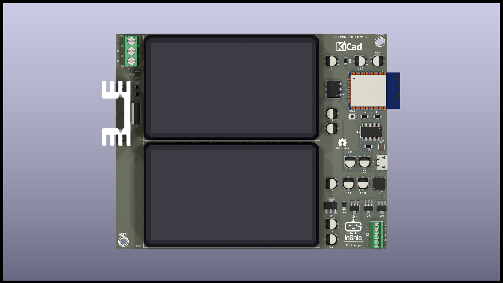
The published component netlist includes:
The supply-module ratings are component ratings, not validated output capabilities of the assembled board. Scheduling, wireless control, efficiency improvements and dimming performance require firmware and testing and are not demonstrated here.
Do not connect the board to mains or send the historical outputs for production based only on this documentation.
The separate RGB+CCT controller explores a five-channel architecture with a nominal 12 V input. It is also a design under review, not a validated replacement product.
| Directory | Purpose |
|---|---|
| KiCAD files | Editable schematic, PCB, project, BOM and netlist |
| PDF Schematic | PDF circuit documentation |
| Release | Renders |
| Manufacturing | Partial historical outputs |
| Firmware | Availability note; no implementation |
| Qty | Value | Footprint | References |
|---|---|---|---|
| 6 | 10uF | Capacitor_SMD:CP_Elec_5x5.4 | C1, C3, C5, C8, C11, C12 |
| 6 | 1uF | Capacitor_SMD:CP_Elec_5x5.4 | C2, C6, C9, C10, C13, C14 |
| 3 | 2N7000 | Package_TO_SOT_SMD:SOT-89-3_Handsoldering | Q2, Q3, Q4 |
| 2 | 10k | Resistor_SMD:R_1206_3216Metric_Pad1.30x1.75mm_HandSolder | R3, R6 |
| 2 | 1k | Resistor_SMD:R_1206_3216Metric_Pad1.30x1.75mm_HandSolder | R4, R5 |
| 1 | 0.01uF | Capacitor_SMD:C_1210_3225Metric_Pad1.33x2.70mm_HandSolder | C4 |
| 1 | 100nF | Capacitor_SMD:C_1210_3225Metric_Pad1.33x2.70mm_HandSolder | C7 |
| 1 | 1N4002 | Diode_SMD:D_PowerDI-123 | D1 |
| 1 | 33 | Resistor_SMD:R_0805_2012Metric_Pad1.20x1.40mm_HandSolder | R2 |
| 1 | BT136-500 | Package_TO_SOT_THT:TO-220-3_Vertical | Q1 |
| 1 | ESP32-WROOM-32 | RF_Module:ESP32-WROOM-32 | U5 |
| 1 | FT232RL | Package_SO:SSOP-28_5.3x10.2mm_P0.65mm | U3 |
| 1 | IN_OUT_AC | TerminalBlock_Phoenix:TerminalBlock_Phoenix_PT-1,5-3-5.0-H_1x03_P5.00mm_Horizontal | J1 |
| 1 | IRM-60-12 | Converter_ACDC:Converter_ACDC_MeanWell_IRM-60-xx_THT_new | PS1 |
| 1 | IRM-60-24 | Converter_ACDC:Converter_ACDC_MeanWell_IRM-60-xx_THT_new | PS2 |
| 1 | LEDs_conx | TerminalBlock_Phoenix:TerminalBlock_Phoenix_MPT-0,5-5-2.54_1x05_P2.54mm_Horizontal | J3 |
| 1 | LM1117-3.3 | Package_TO_SOT_SMD:SOT-223-3_TabPin2 | U1 |
| 1 | LOGO | footprints:logo ingnia 3000x | G*** |
| 1 | MOC3021M | Package_TO_SOT_THT:DIP762W45P254L889H508Q6_NEW | U2 |
| 1 | PCA9685BS | Package_DFN_QFN:QFN-28-1EP_6x6mm_P0.65mm_EP4.25x4.25mm | U4 |
| 1 | R | Resistor_SMD:R_0805_2012Metric_Pad1.20x1.40mm_HandSolder | R1 |
| 1 | SW_Push | Button_Switch_SMD:SW_SPST_B3U-1000P | SW1 |
| 1 | USB_OTG | Connector_USB:USB_Micro-B_Molex_47346-0001 | J2 |
The 37 most common of 42 parts.
It measures 134.4 × 106.7 mm and has 2 copper layers, 1.6 mm thick.
42 parts, built around the ESP32-WROOM-32, IRM-60-12, IRM-60-24 and FT232RL. The full list of its parts is on this page, with links to each part's symbol and footprint where PCBKit's library has them.
From the MbFredys/PCB-LEDs-Controller repository on GitHub, at the commit this page was made from: the board is KiCAD files/led-controller.kicad_pcb and its schematic KiCAD files/led-controller.kicad_sch. PCBKit opens the board in the browser, with nothing to install.
Its repository states no licence, so its author keeps all rights: ask MbFredys before reusing the design.

BayLibre/Labrack
A standard 1U rack front panel metal sheet and PCB providing power, connectivity and more.

smariel/SonosPlay1Hack
Sonos Play:1 replacement with RaspberryPi


kyledenobel/RGA_Boards
PCB Board design and development for RGA (Recording Guitar Amplifier)


sea2-dsi-fceia/PLACA_IOT_INDUSTRIAL
Placa de desarrollo para aplicaciones industriales IoT basada en ESP32 (Open Source)