2 layers179.1 × 182.3 mm
 BayLibre/Labrack1
A standard 1U rack front panel metal sheet and PCB providing power, connectivity and more.
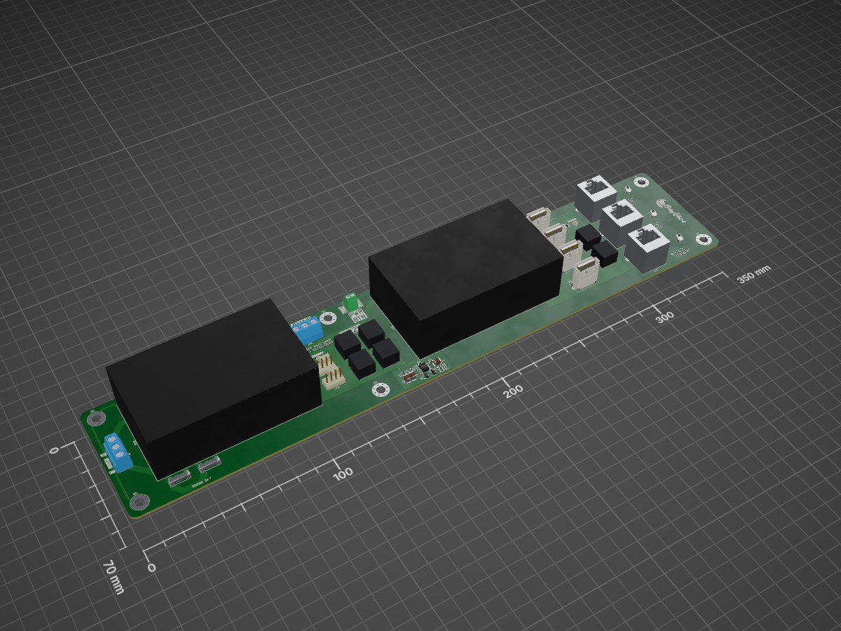
Rack Front Panel is an open-source printed circuit board by BayLibre, from the BayLibre/Labrack repository on GitHub. It is a 2-layer board of 350 × 70 mm with 50 parts on 99 nets, routed with 214 tracks and 22 vias.
It is built around the IRM-60-12, IRM-60-5 and LM393DT, with the PJ-044BH, SS-90000-013 and USB1086-GF-B among its other parts. Its parts include 21 connectors, 9 resistors, 4 capacitors, 2 diodes and 2 transistors.


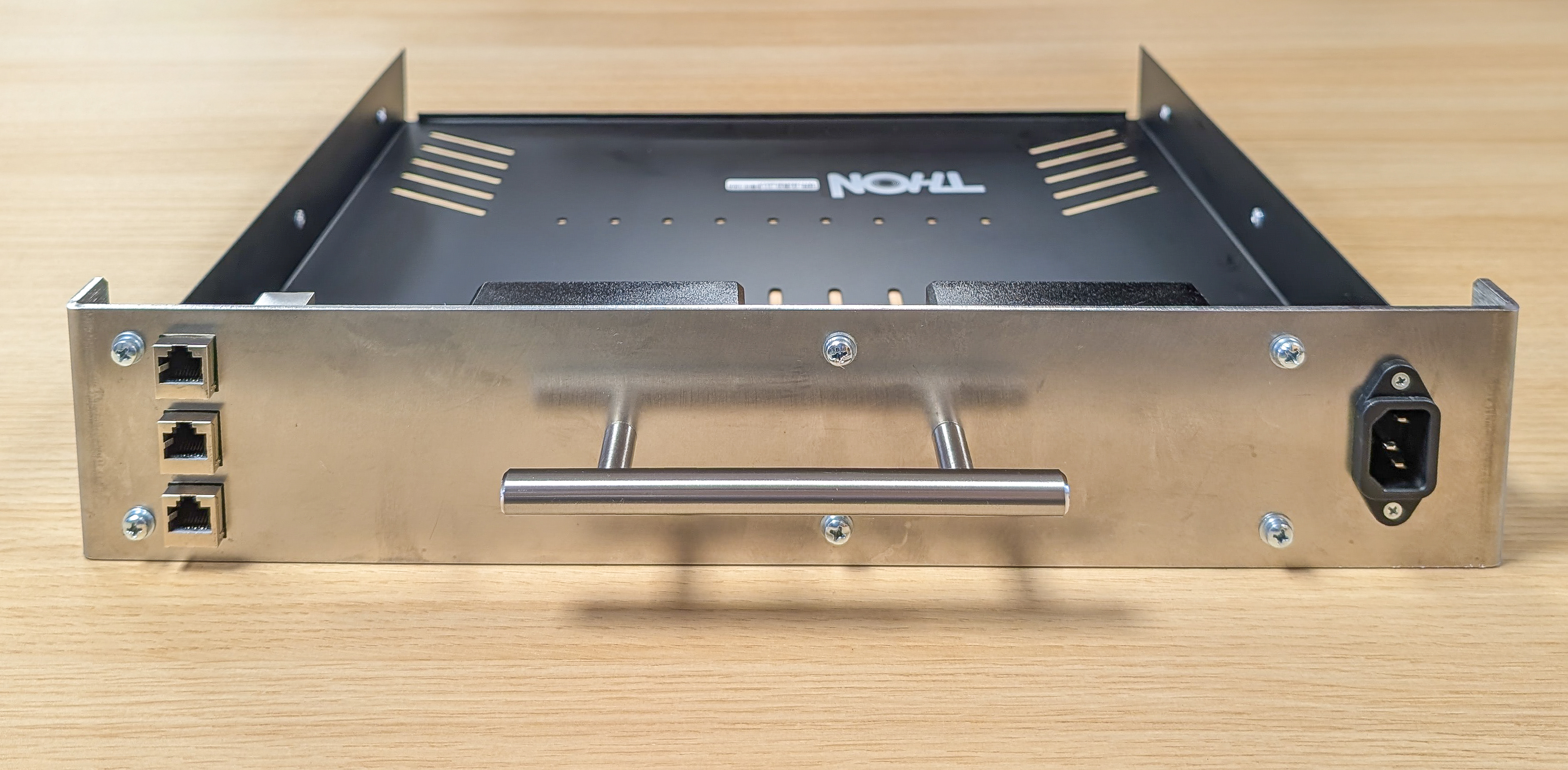
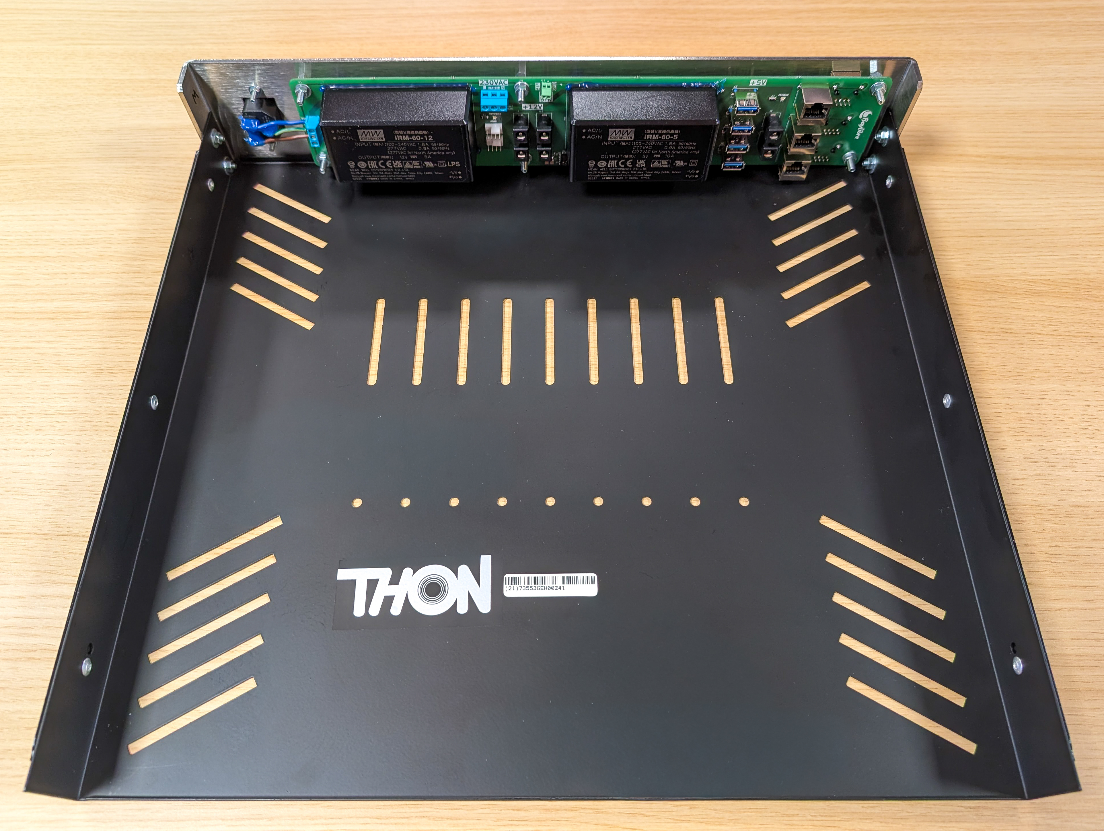
A robust and efficient front panel for standard 1U rackable drawers that provides the following features :
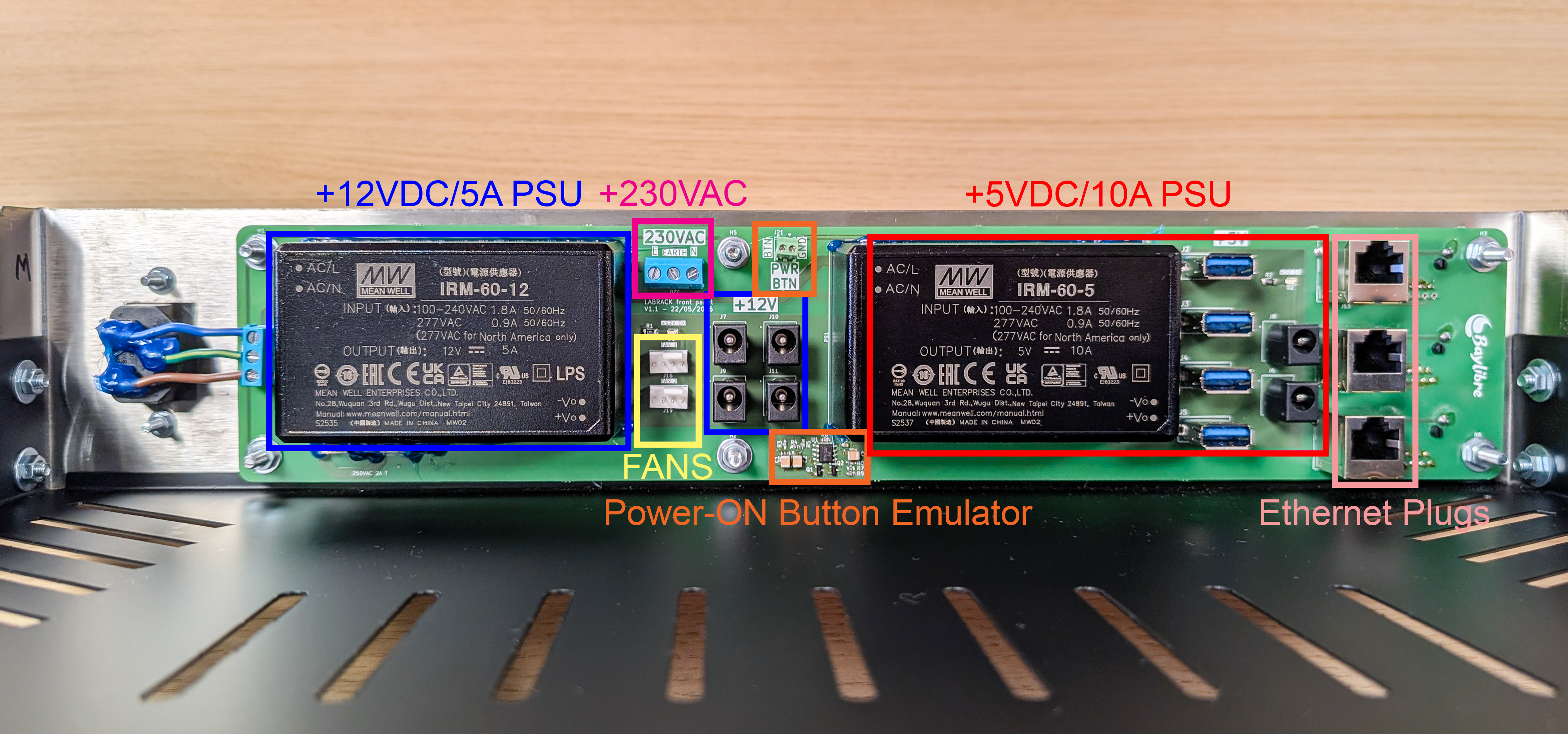
All the parts needed in addition to the front panel metal sheet and the assembled PCB.
Needed parts :
When the PCB has been fully assembled, glue the top side of the AC/DC blocks in order to secure them onto the PCB surface, as they are quite heavy.
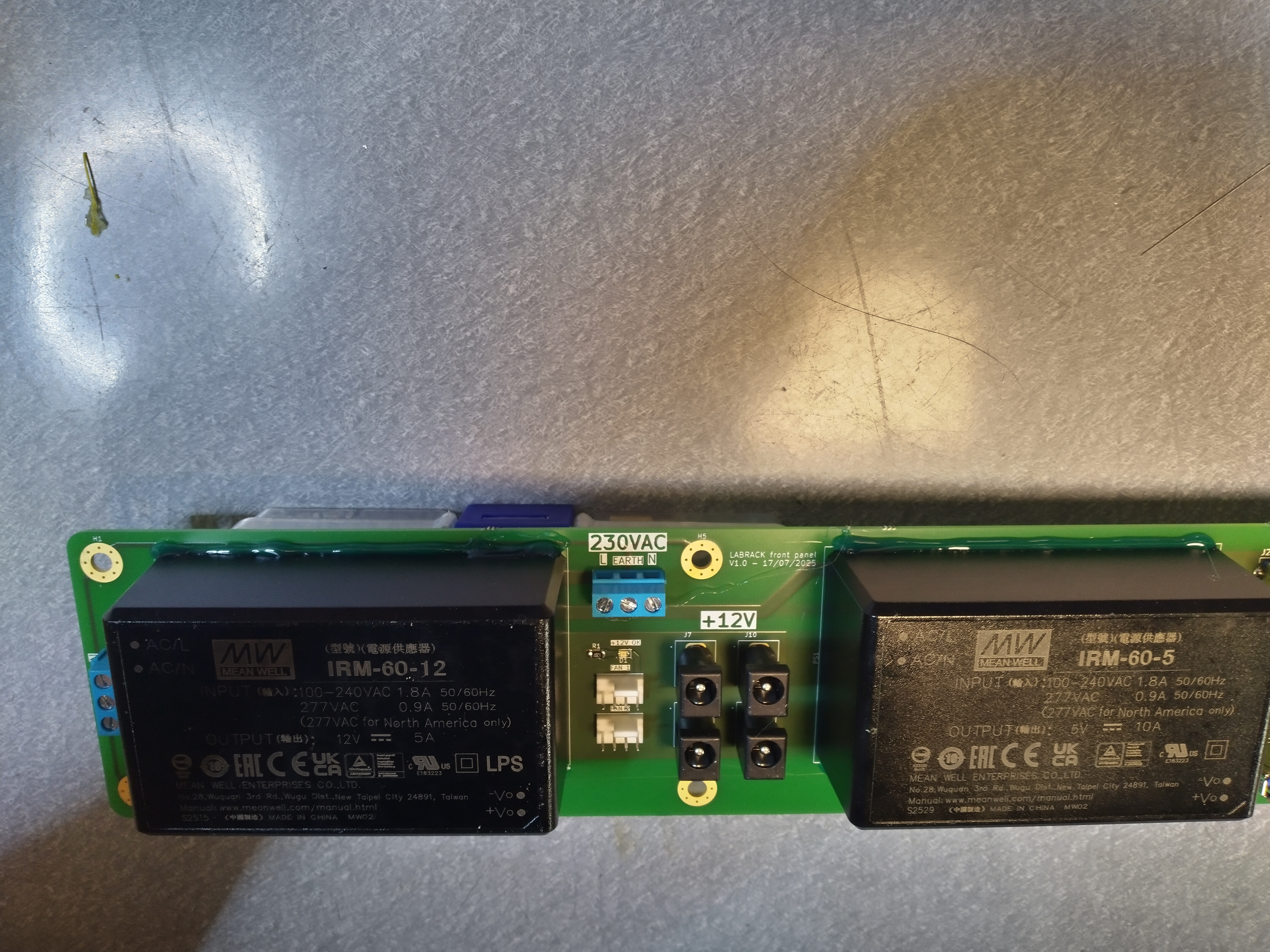
Then glue the bottom side of the AC/DC blocks. Also glue the fuses exposed contacts to avoid anyone touching the mains voltage.
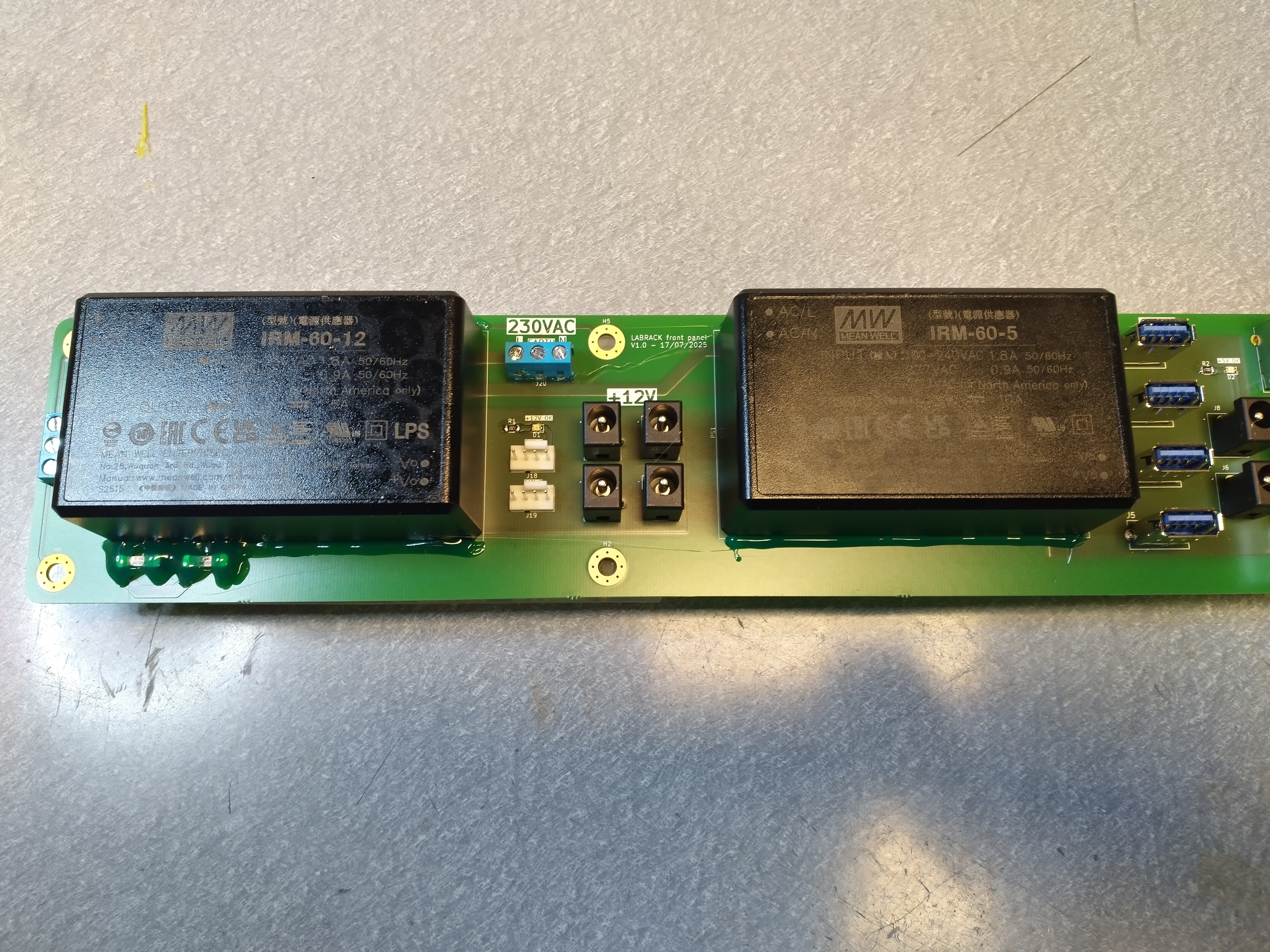
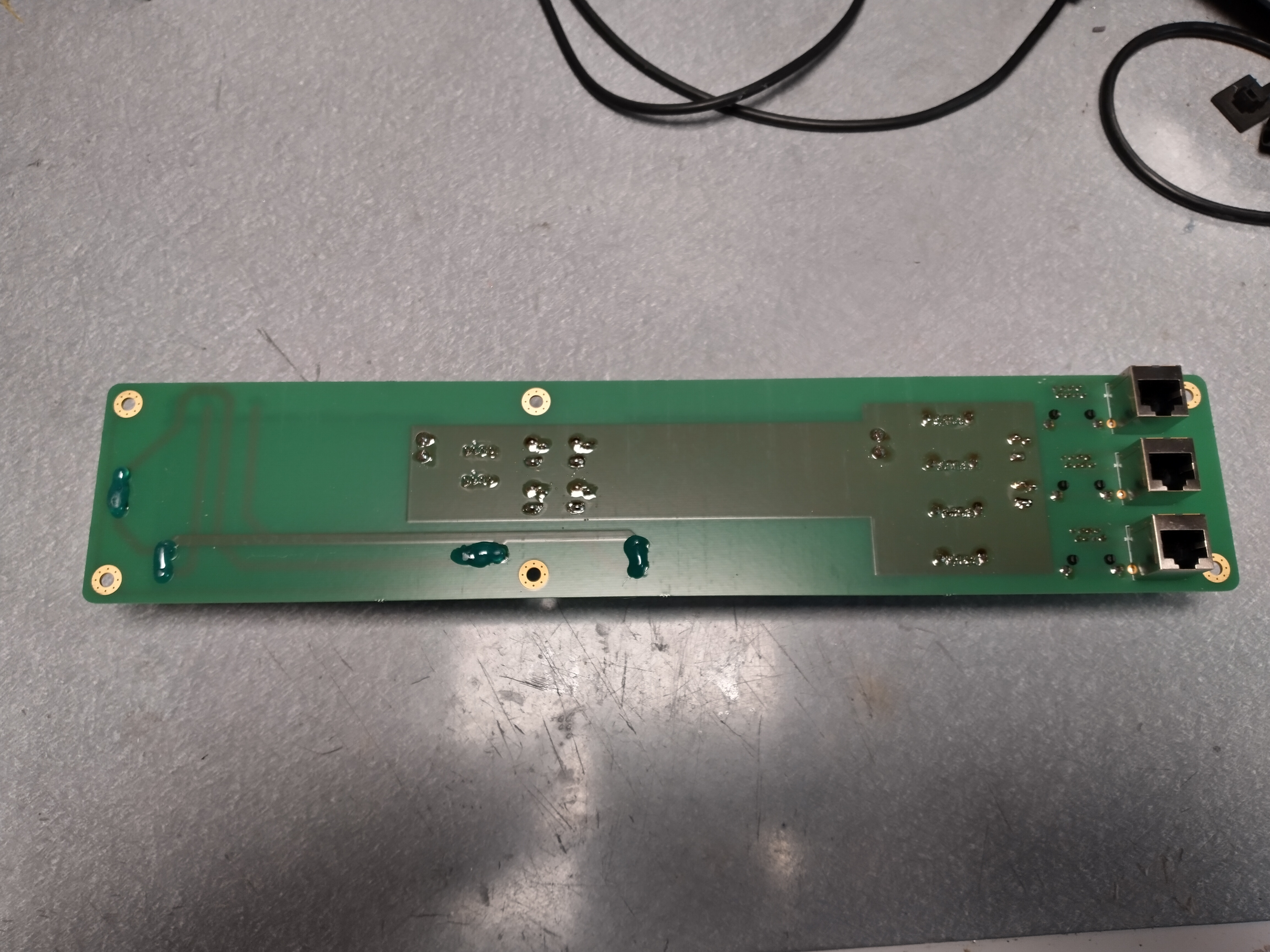
Finally, turn the PCB and glue the four locations where the mains voltage is present.
Peel the protective film from the front metal panel (if any).
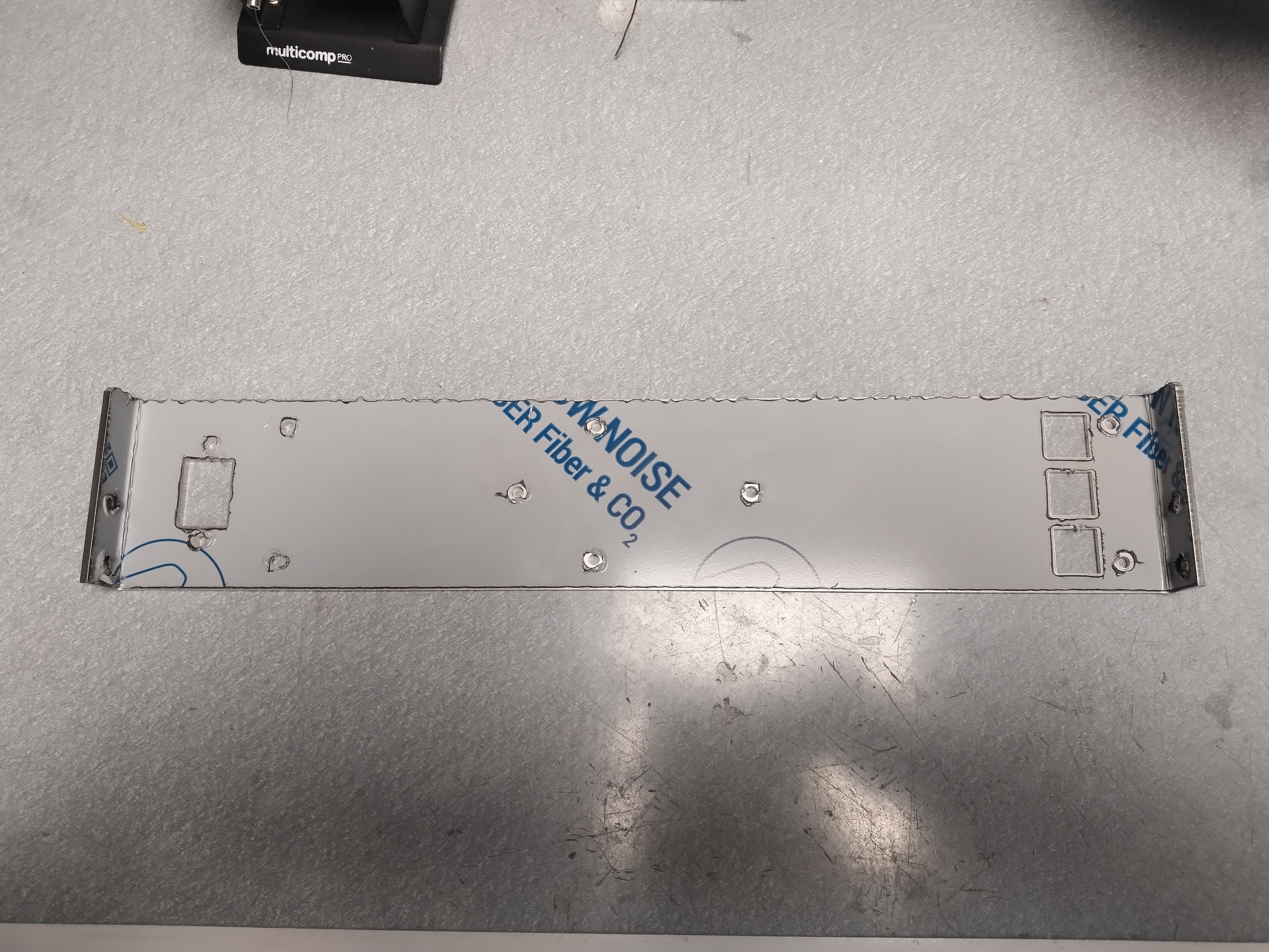
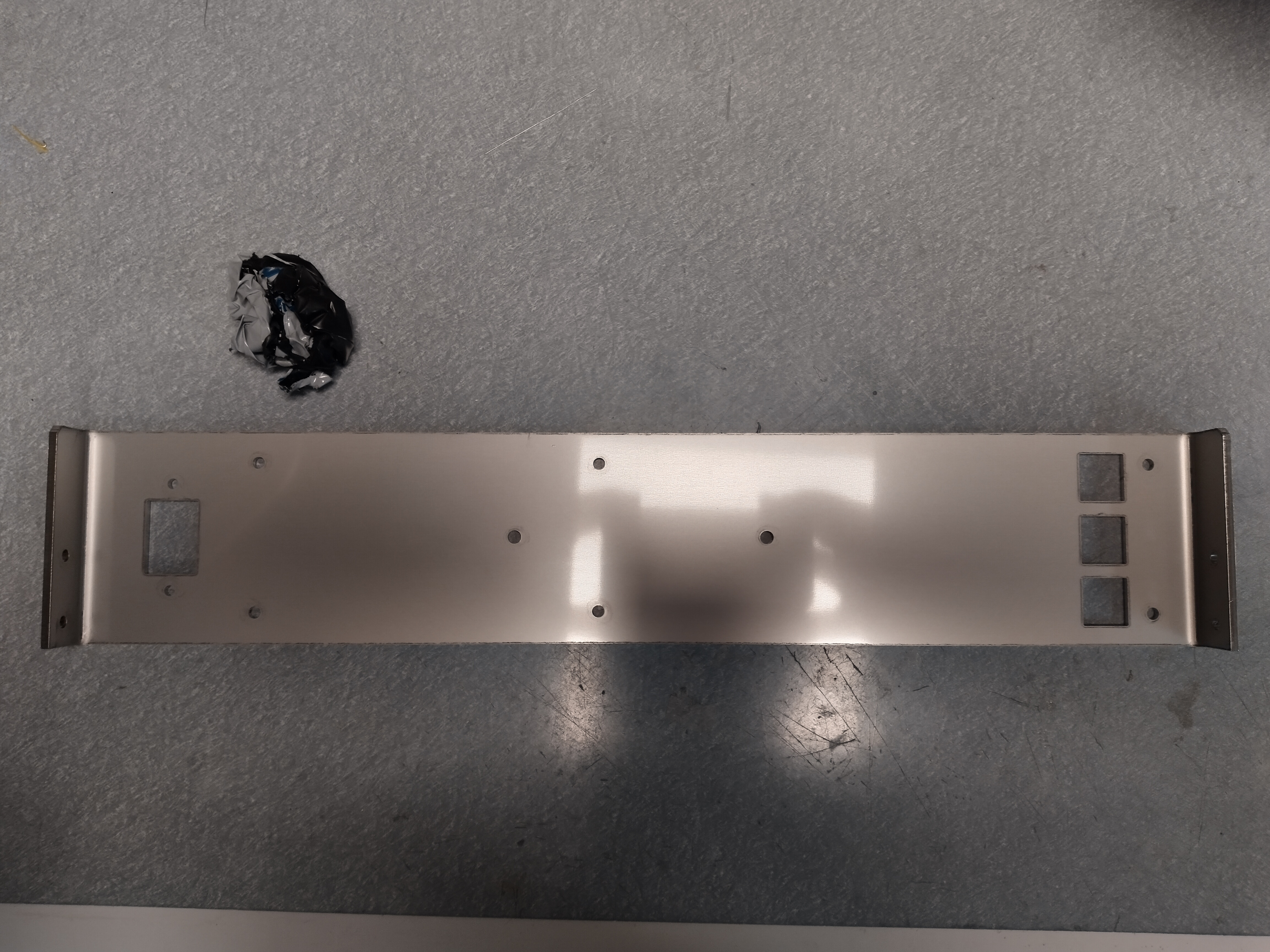
Bolt one 25mm M4 screw, along with one M4 spacer and one M4 washer to the bottom-down middle hole. This bolt will later hold the PCB.
The purpose of putting this bolt now is to index the front metal panel on top of the rack drawer bottom plate, because sometimes this drawer is bent.
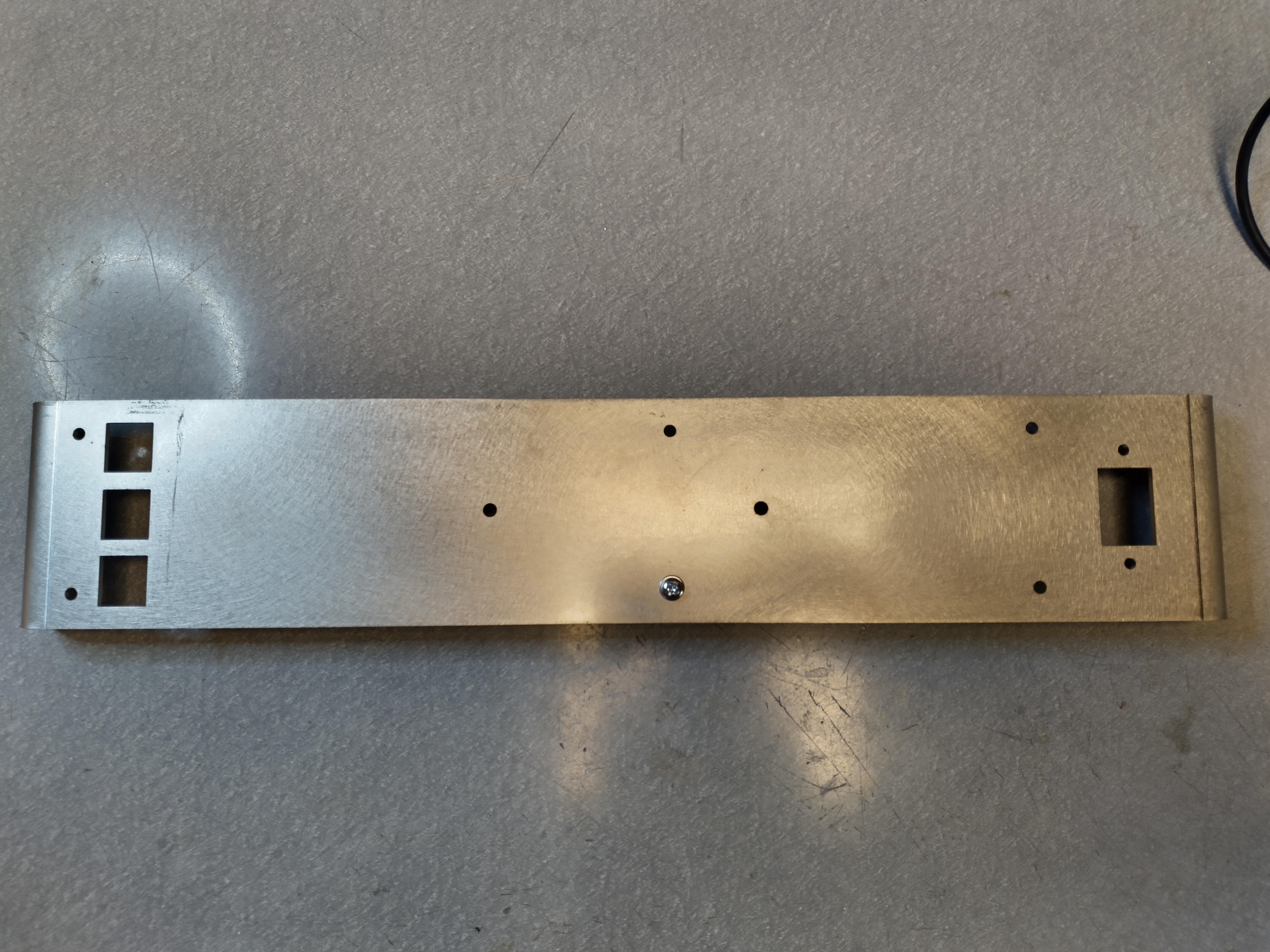
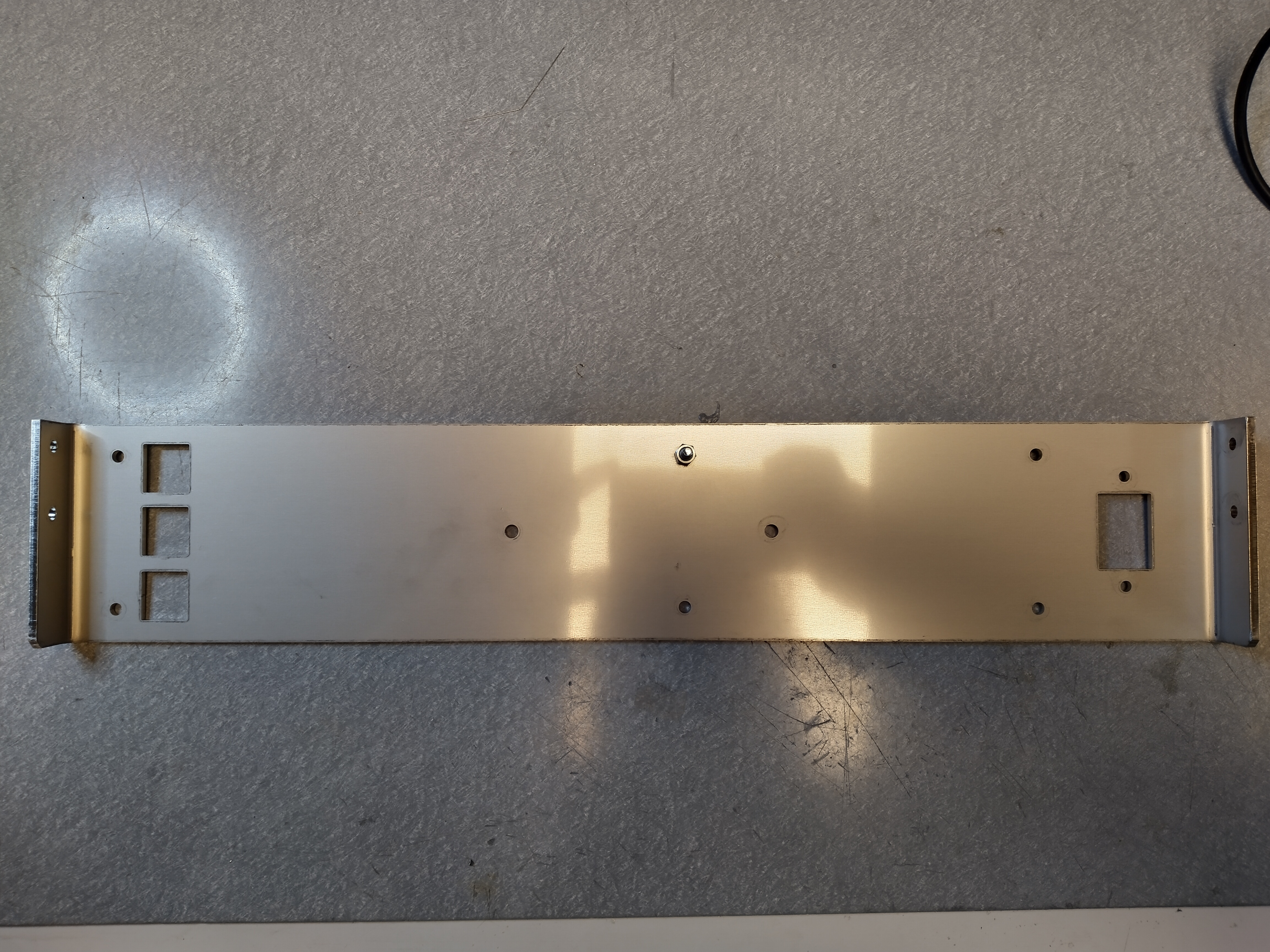
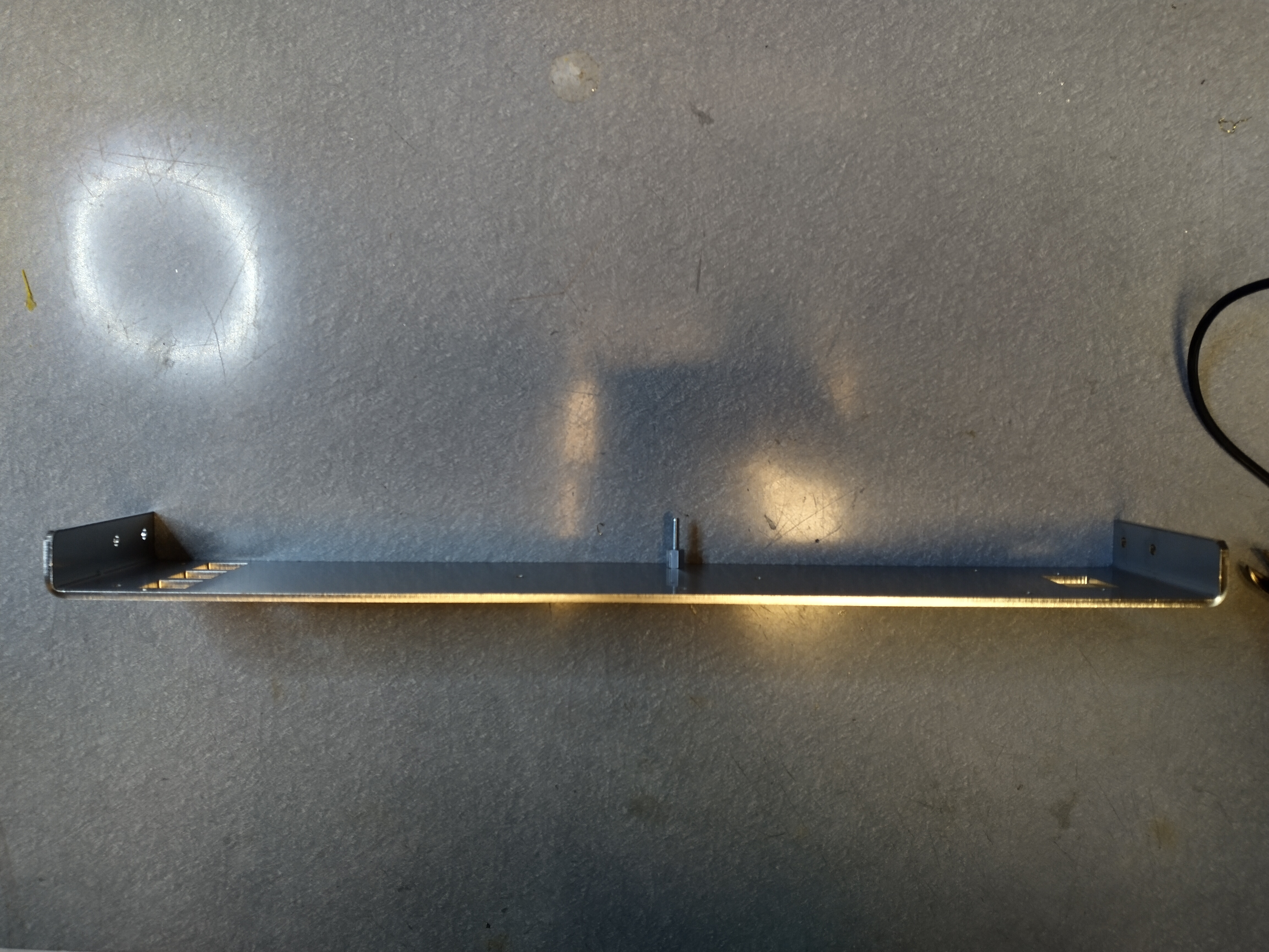
Unpack the rack drawer.
Put the opening side in front of you. The front metal panel will be bolted to this side.
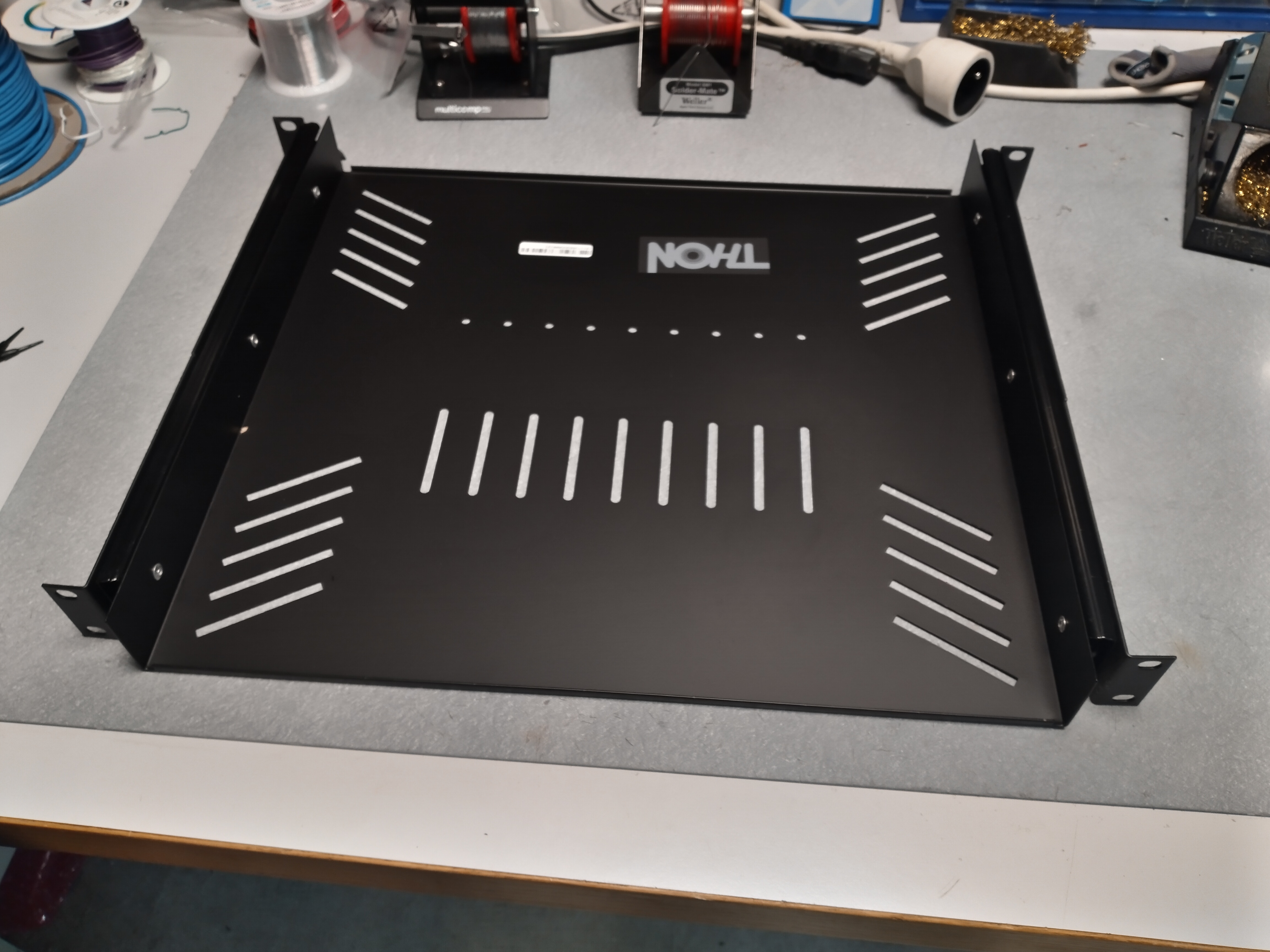
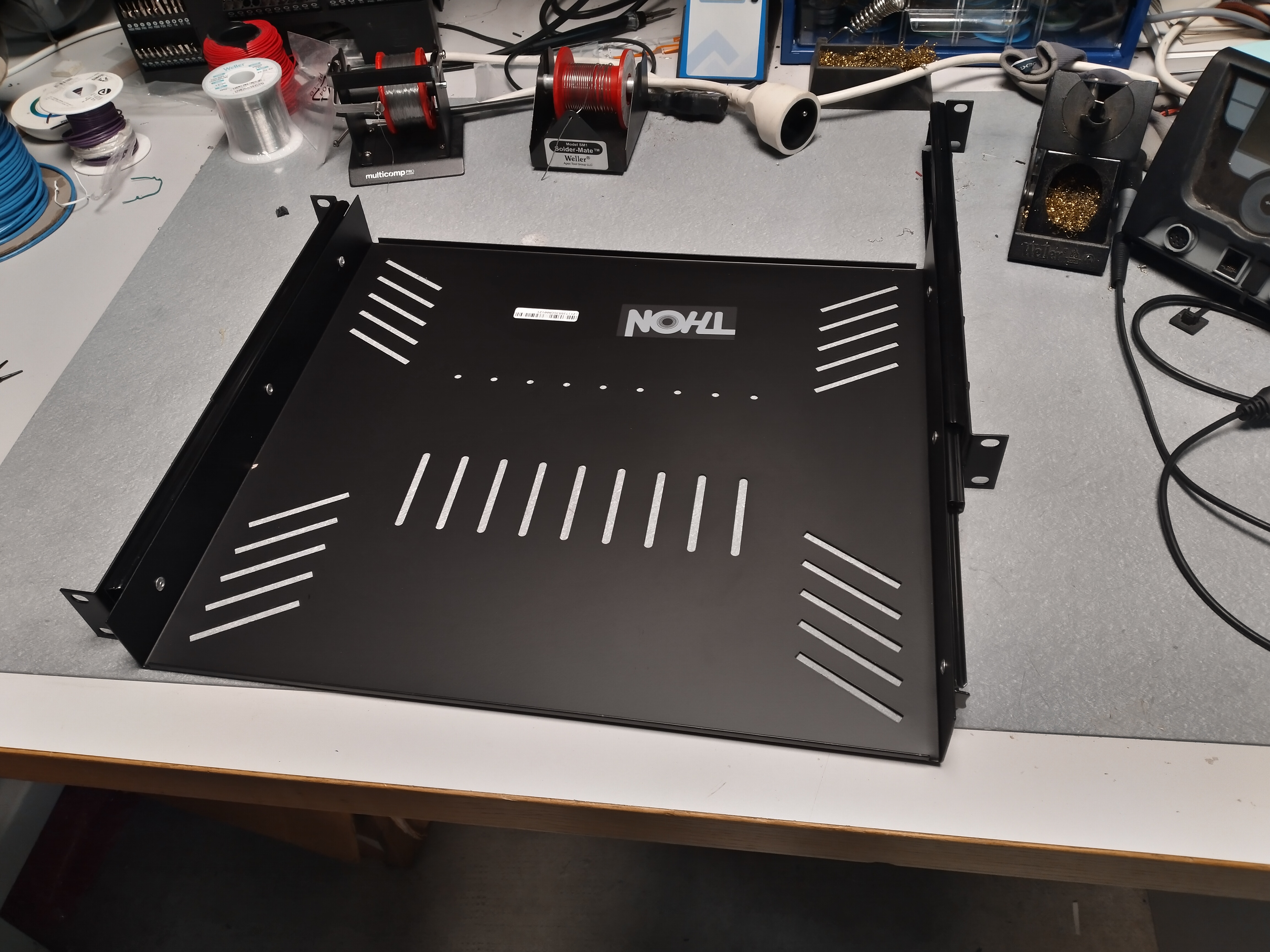
Put the front metal panel in position.
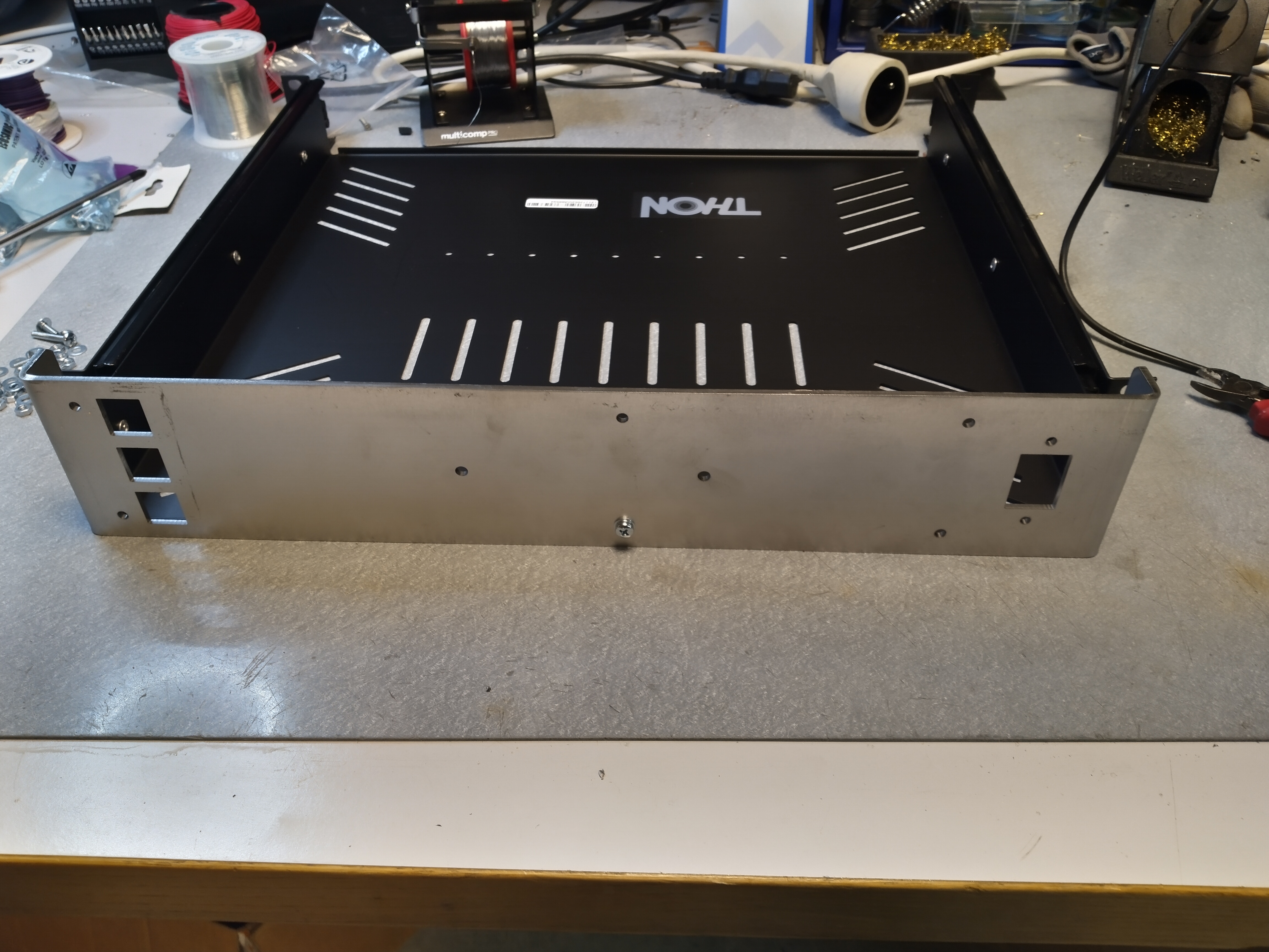
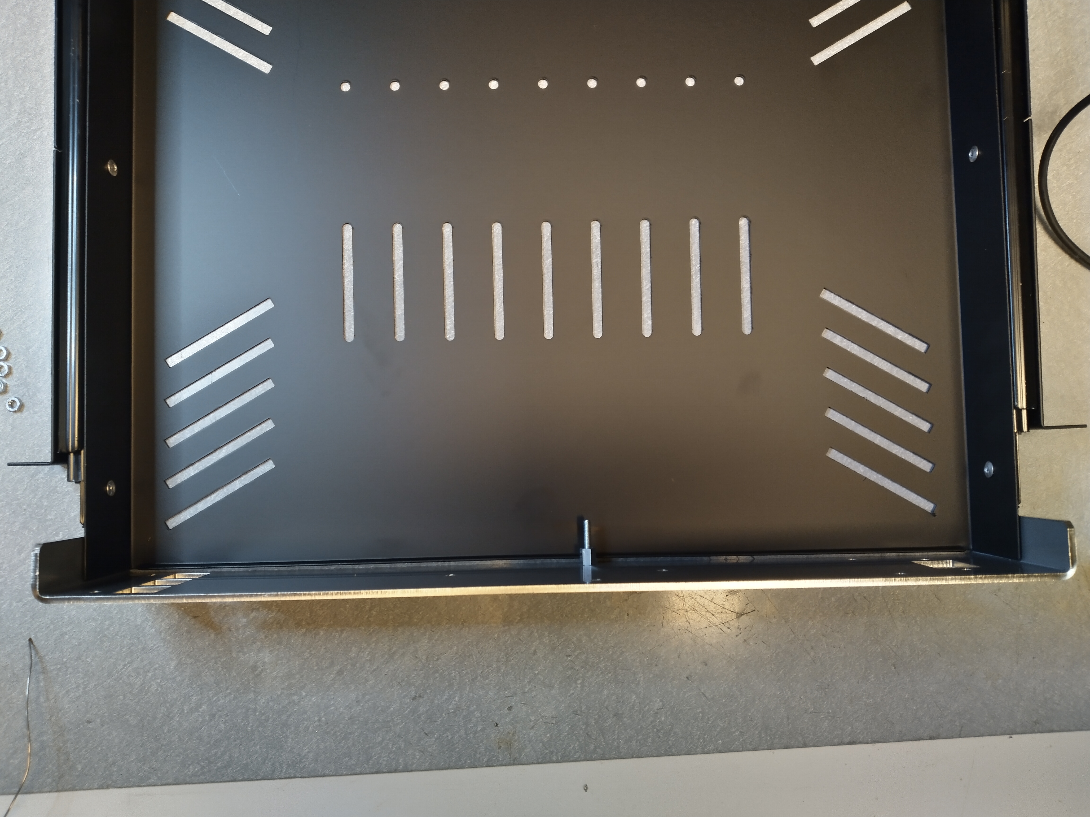
Mark the four front metal panel holes thanks to the punch tool.
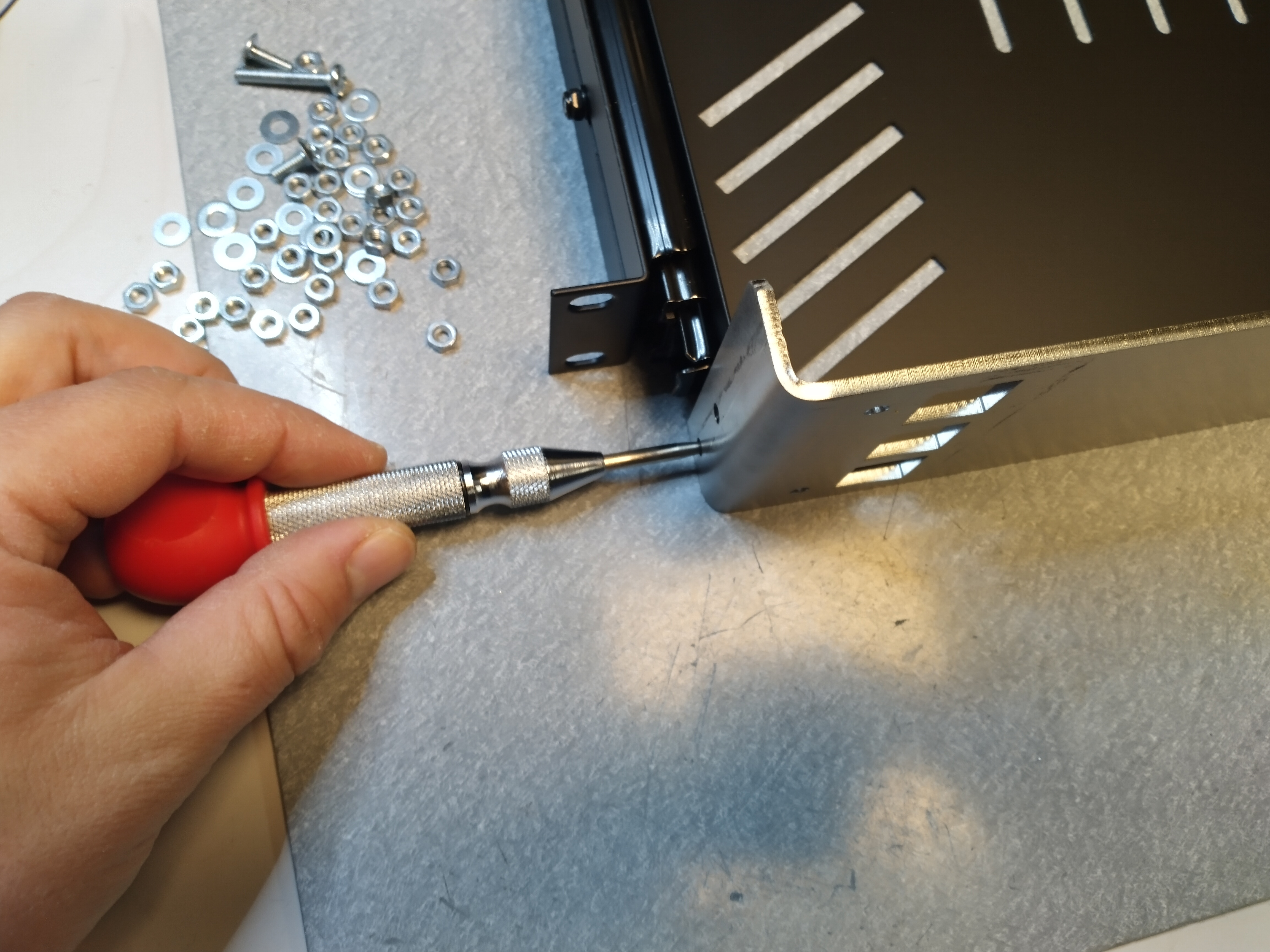
Drill the four holes on the rack drawer with a 4.5mm drill bit.
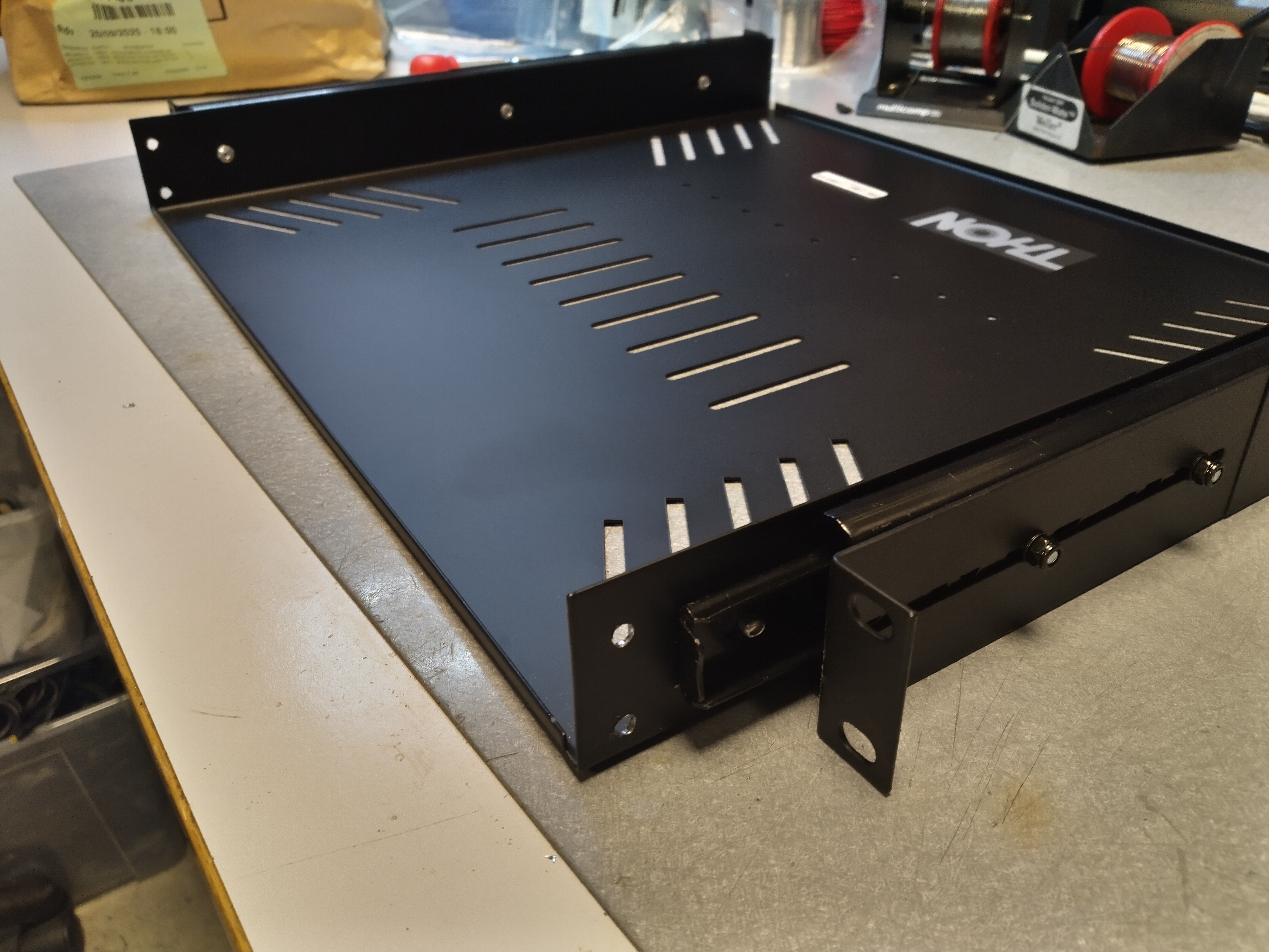
Bolt the front metal panel to the rack drawer, using four 10mm M4 screws, four M4 nuts and four M4 washers.
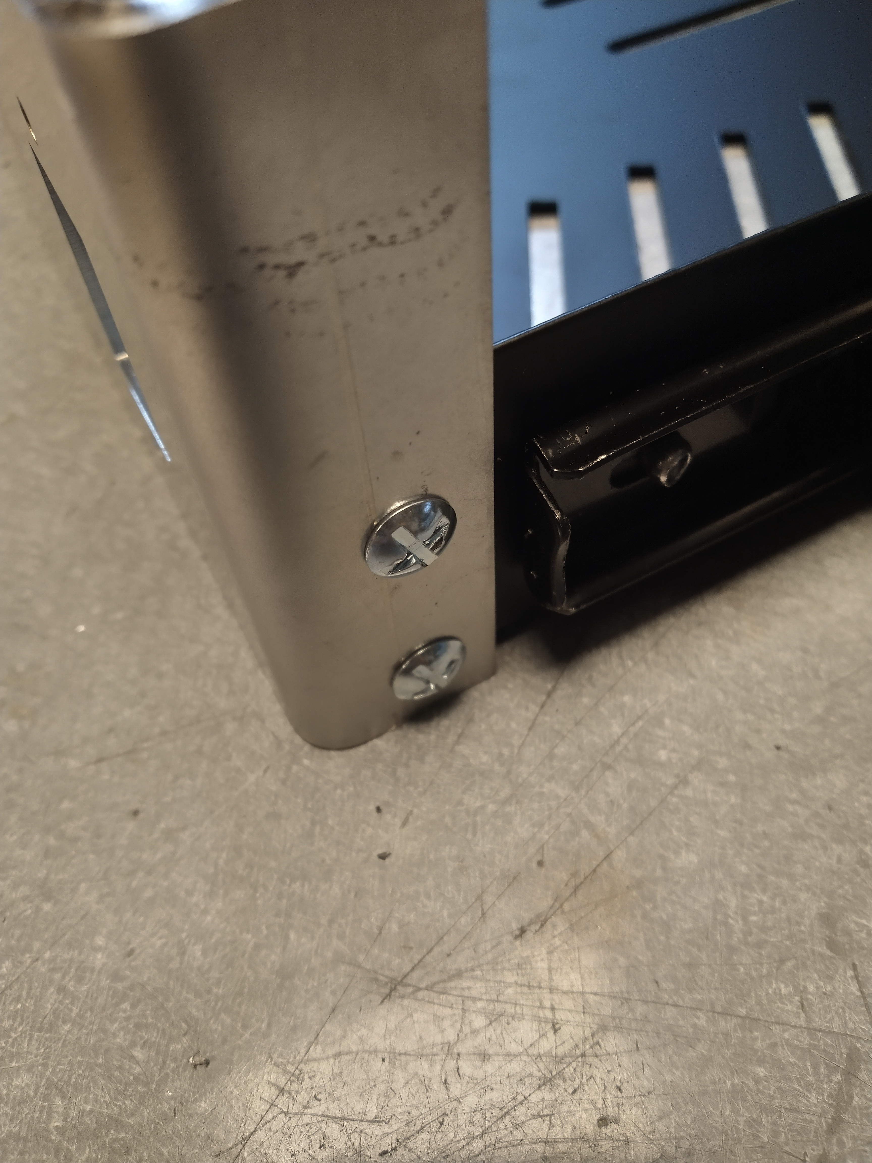
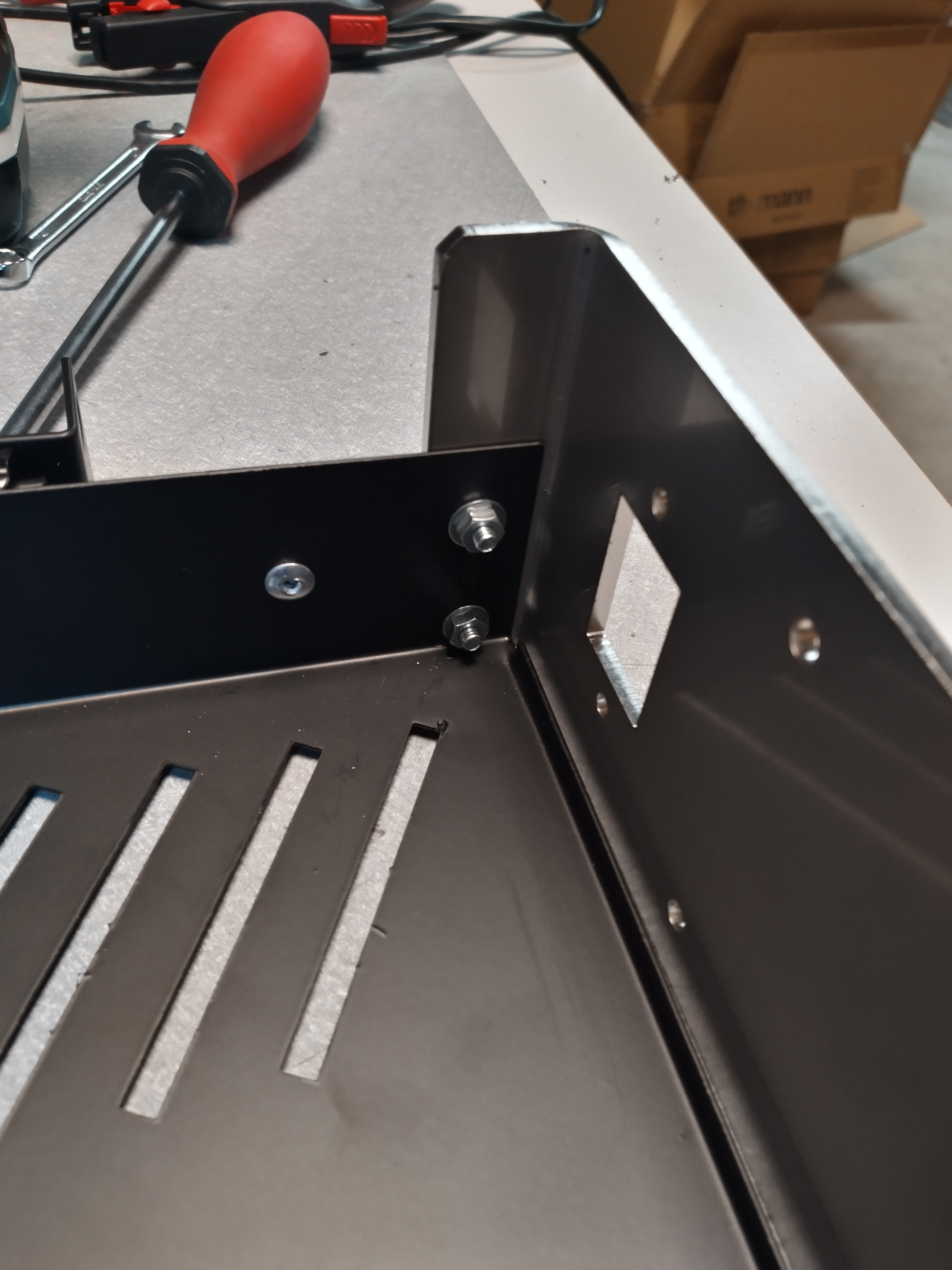
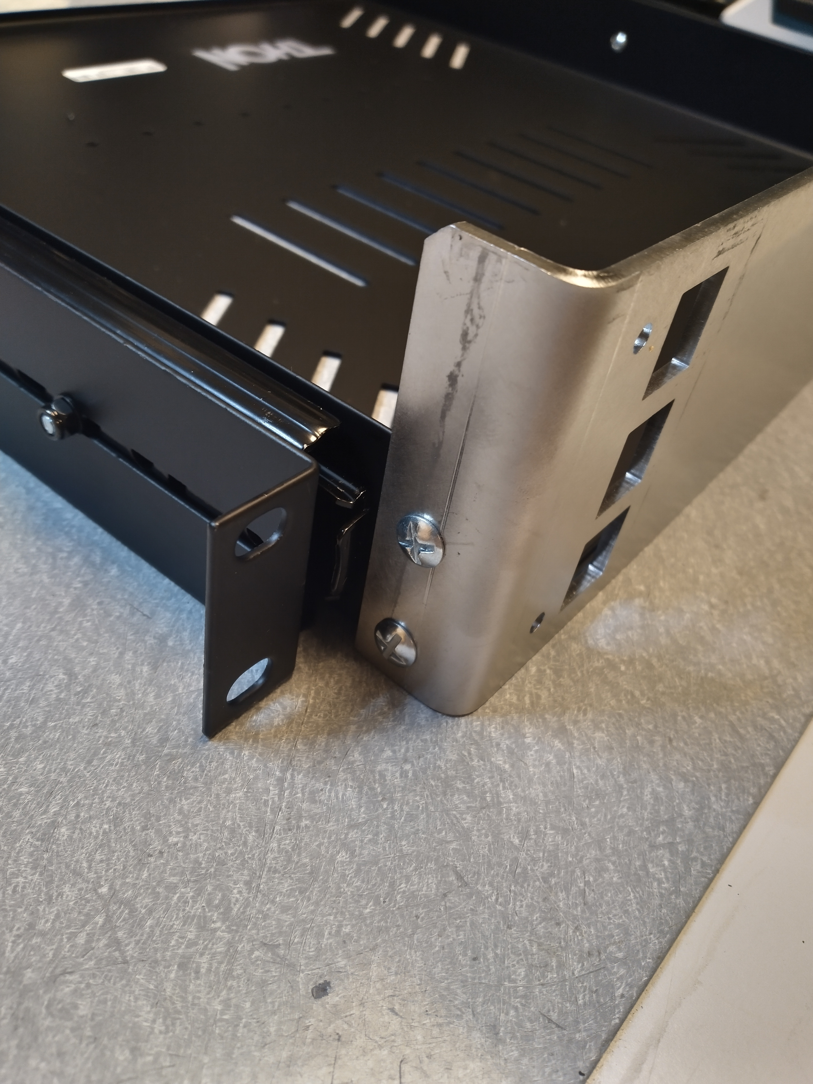
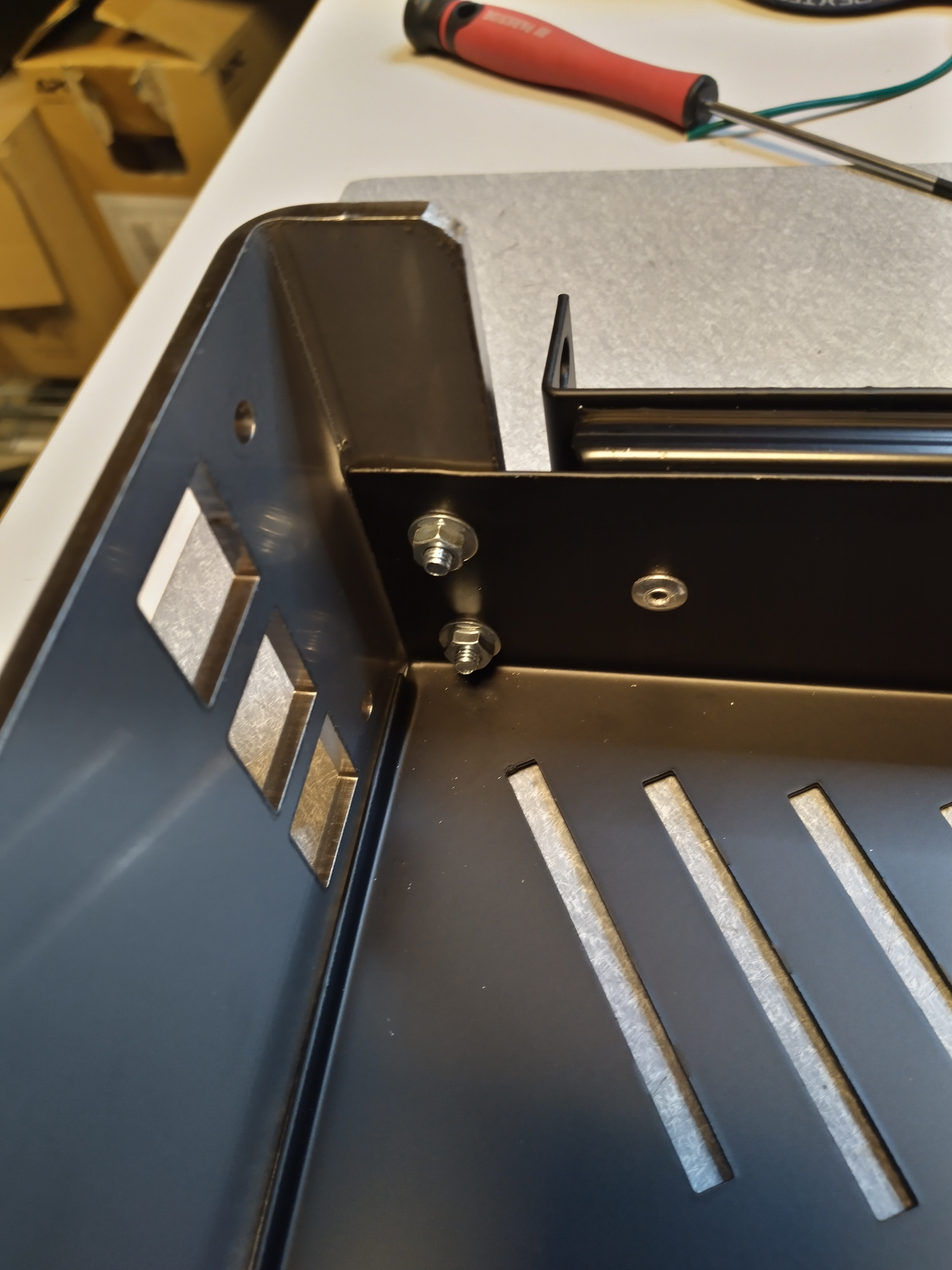
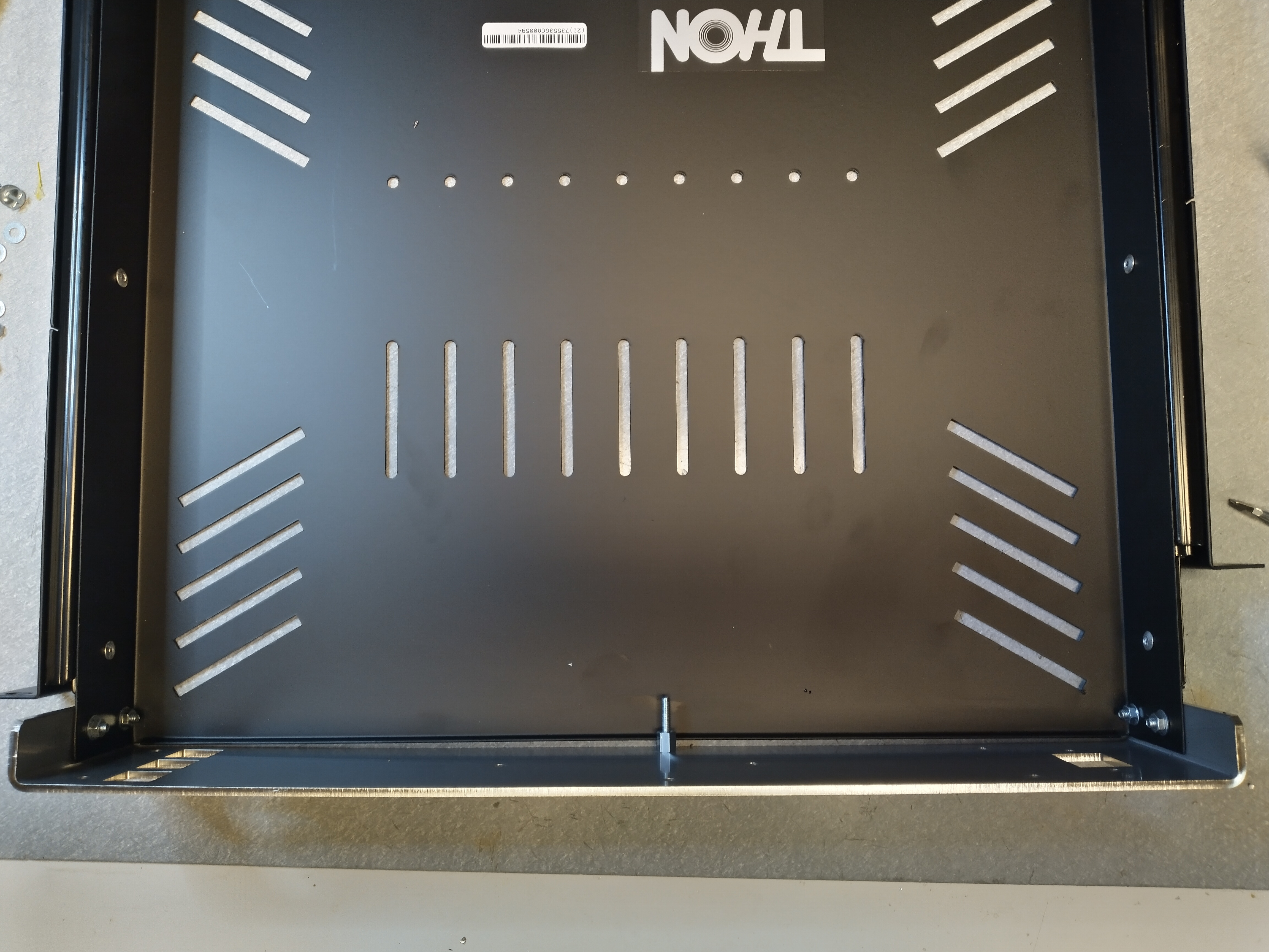
Add the five missing PCB holding 25mm M4 bolts, along with five M4 spacers and five M4 washers.
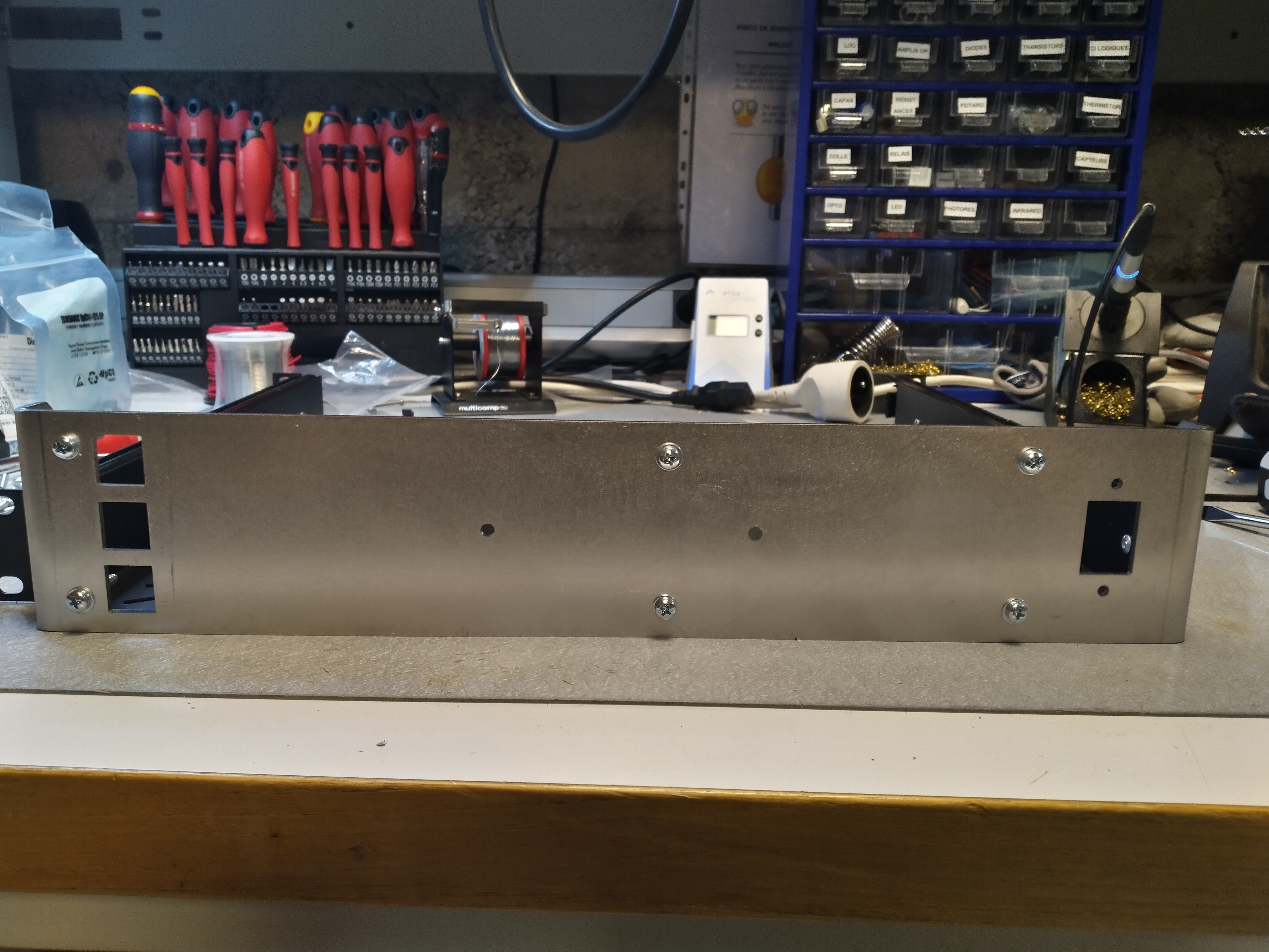
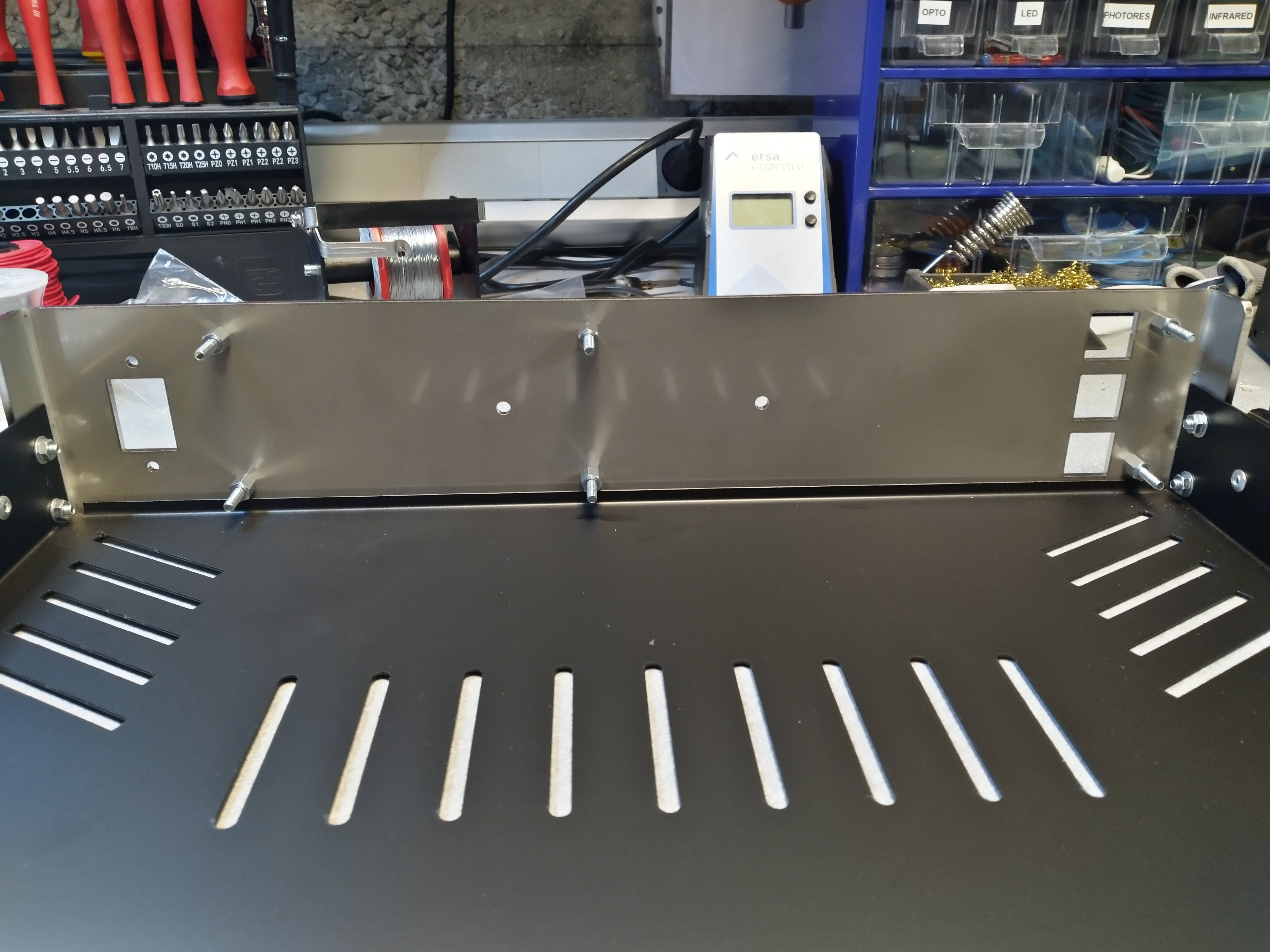
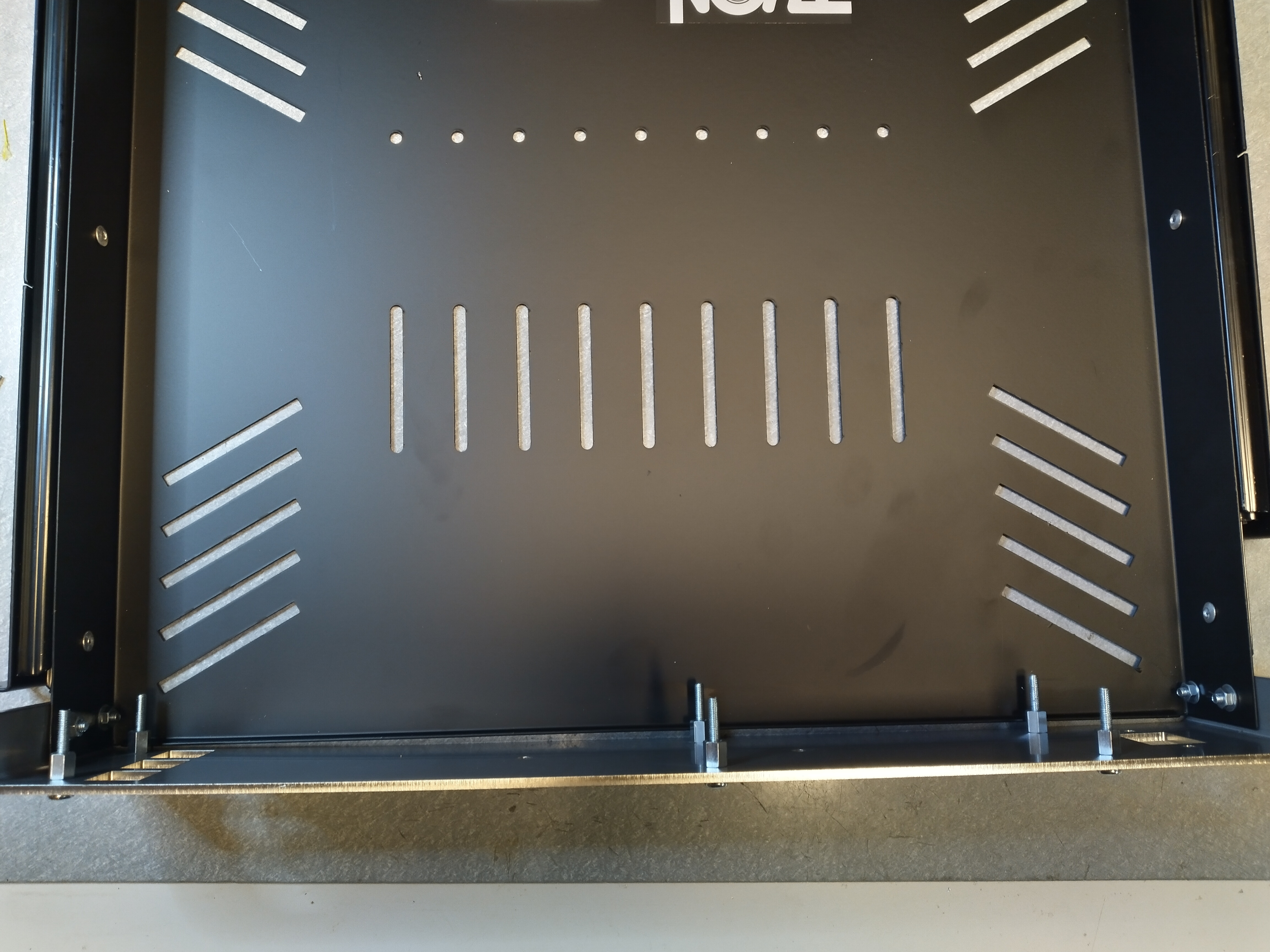
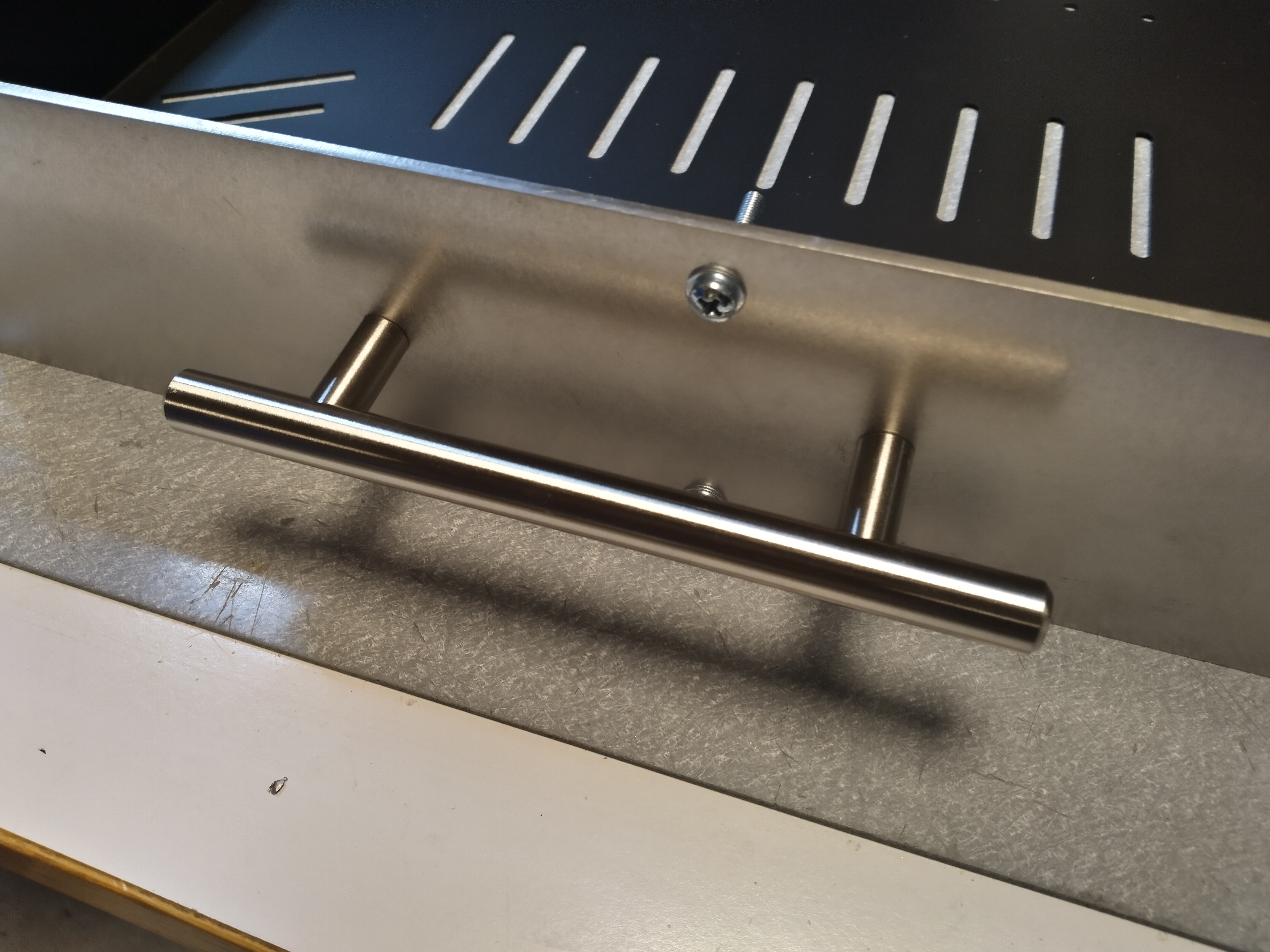
Attach the handle to the front metal panel with the help of two 10mm M4 screws and two M4 washers.
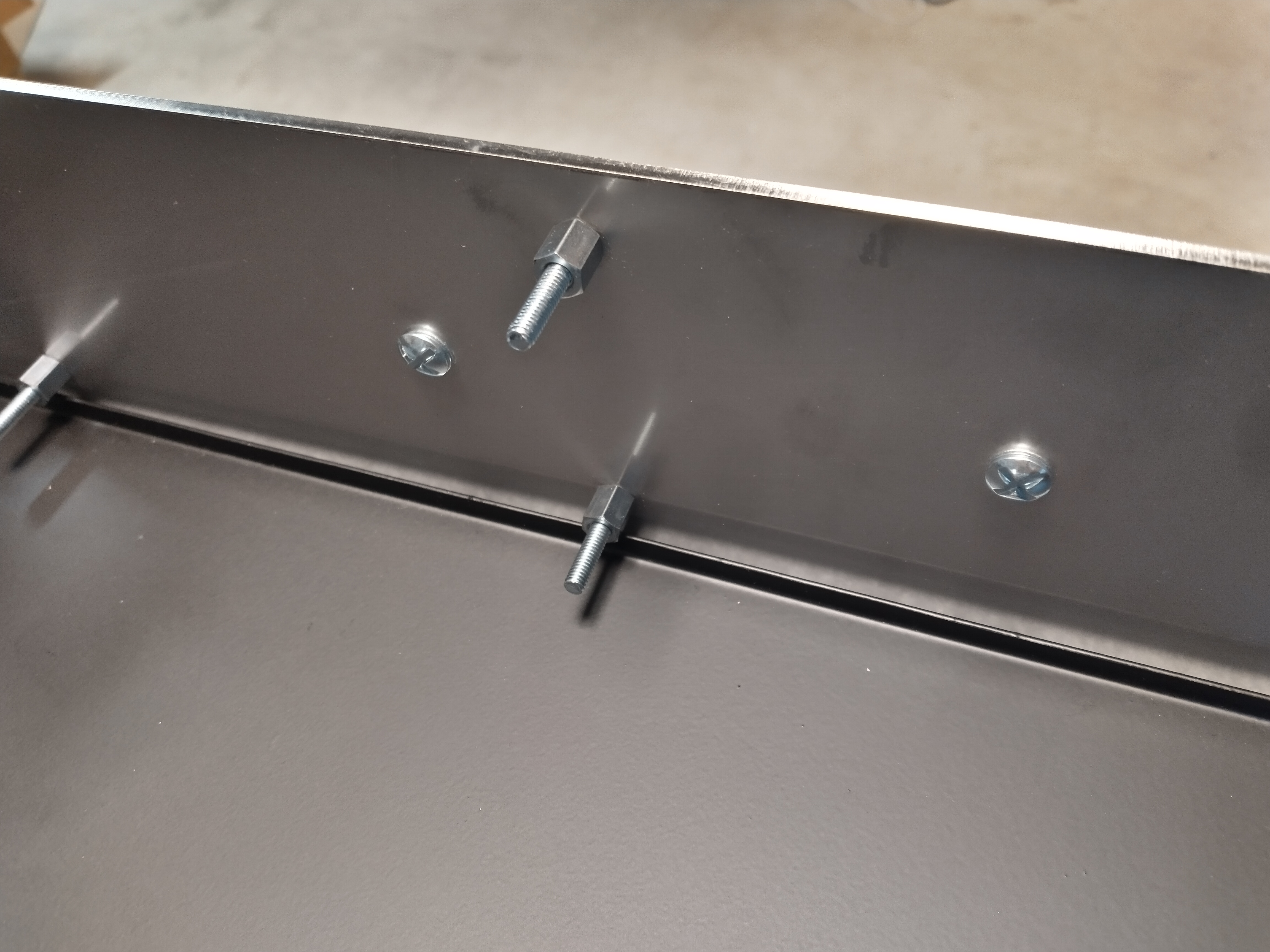
Place the PCB in the six bolts with spacers, then bolt it by using six M4 nuts and six M4 washers.
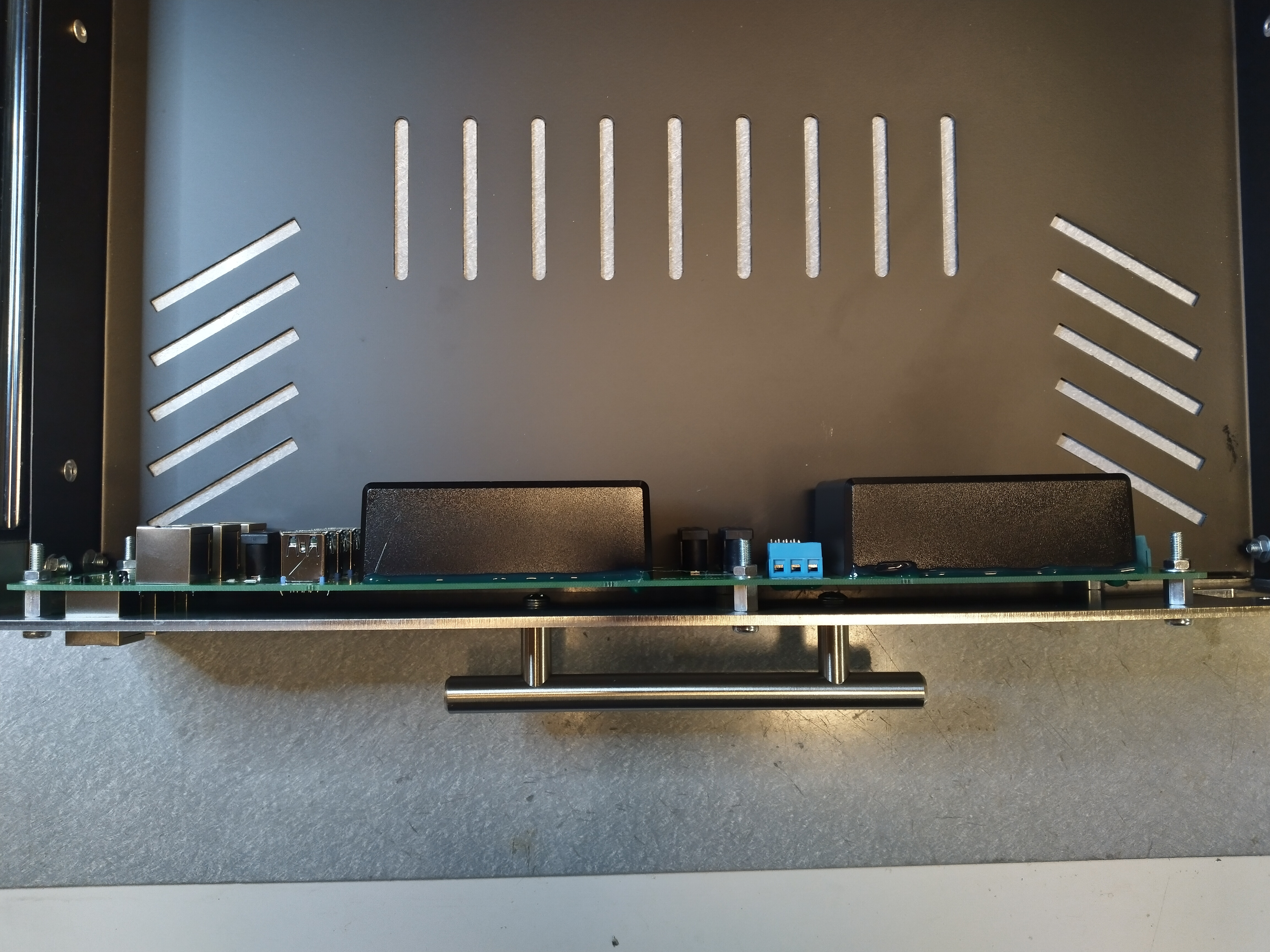
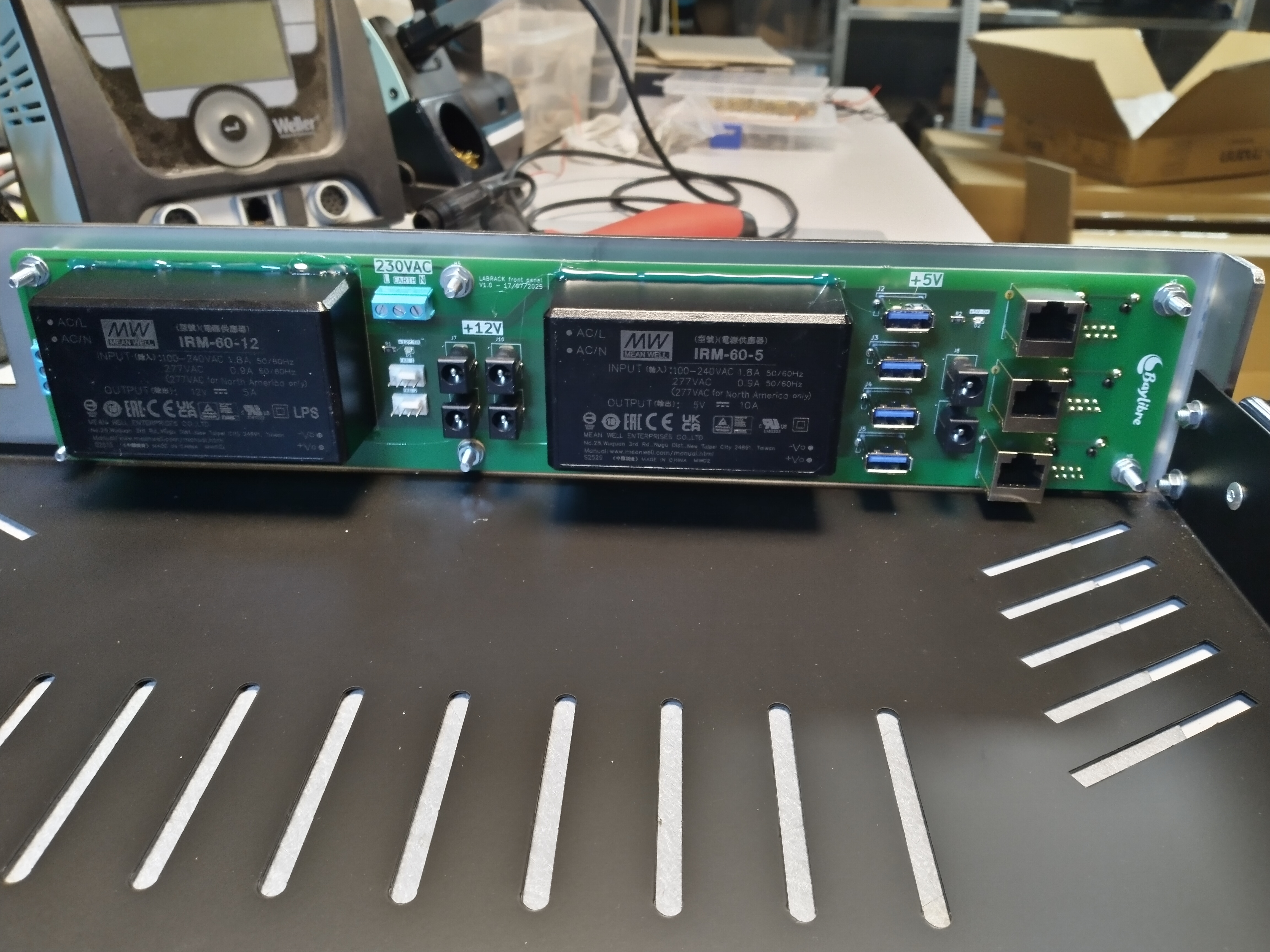
Place the IEC connector with the longest edge located on the drawer outside.
Bolt it with two 16mm M3 screws, two M3 nuts and two M3 washers.
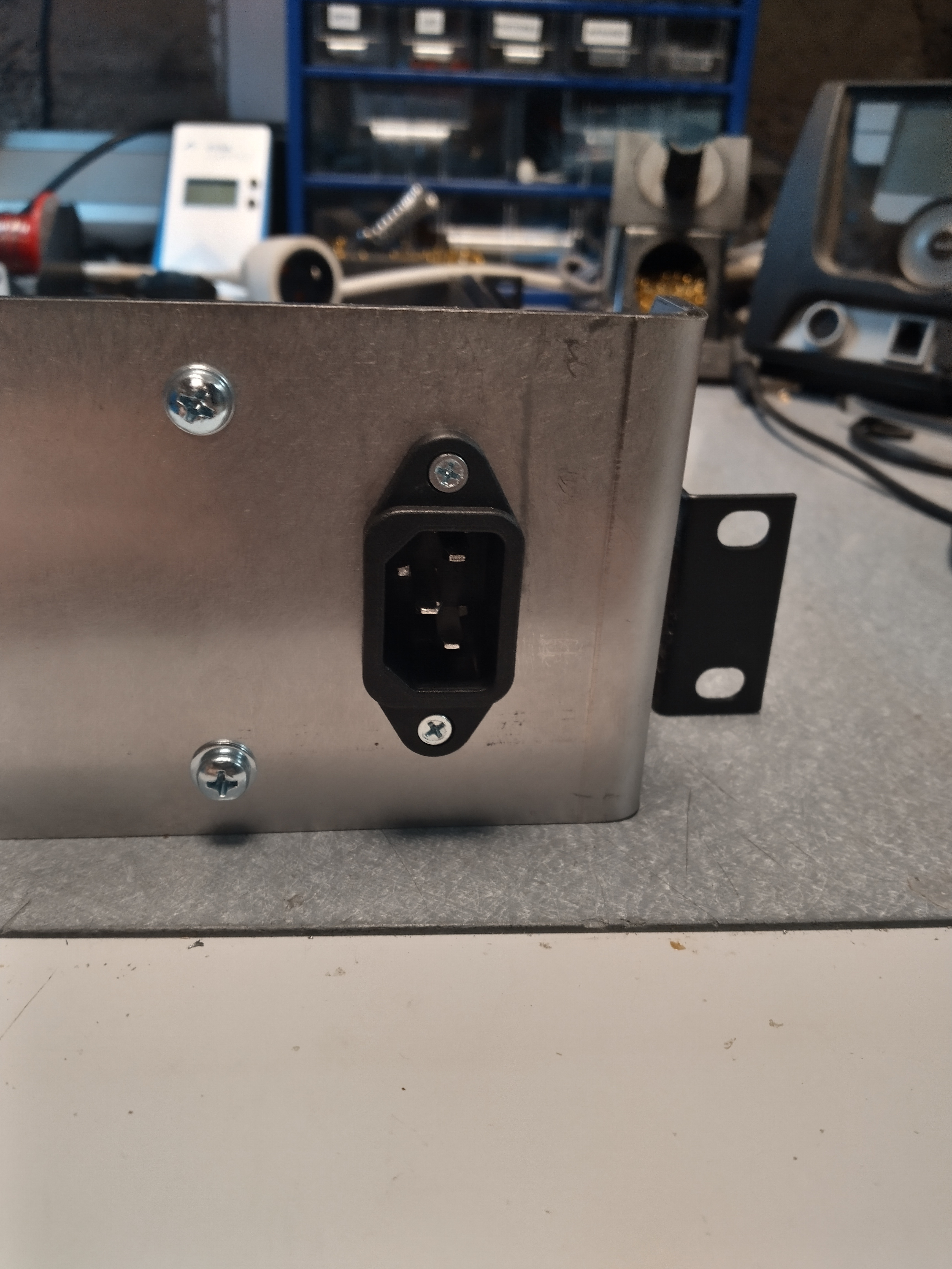
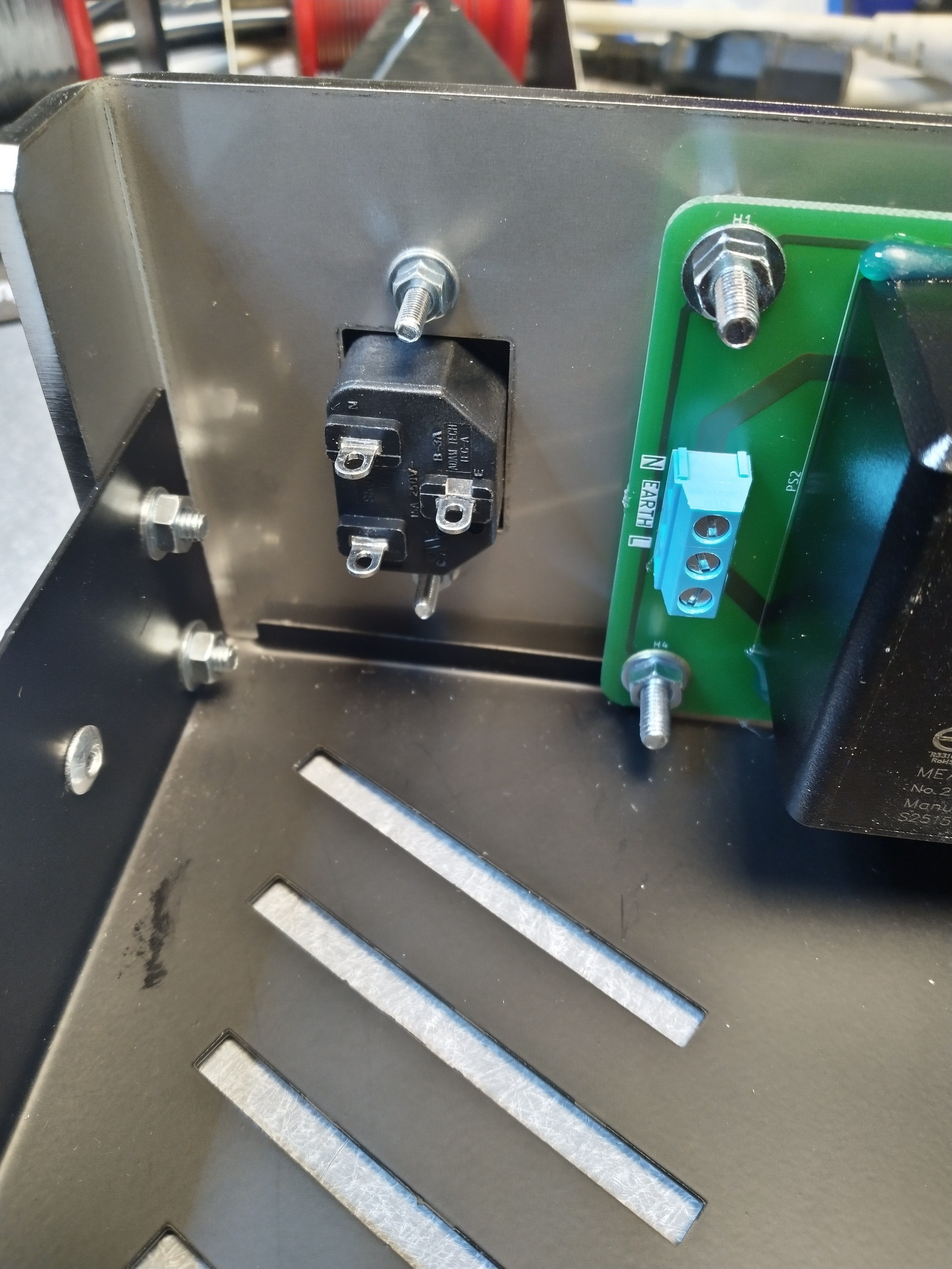
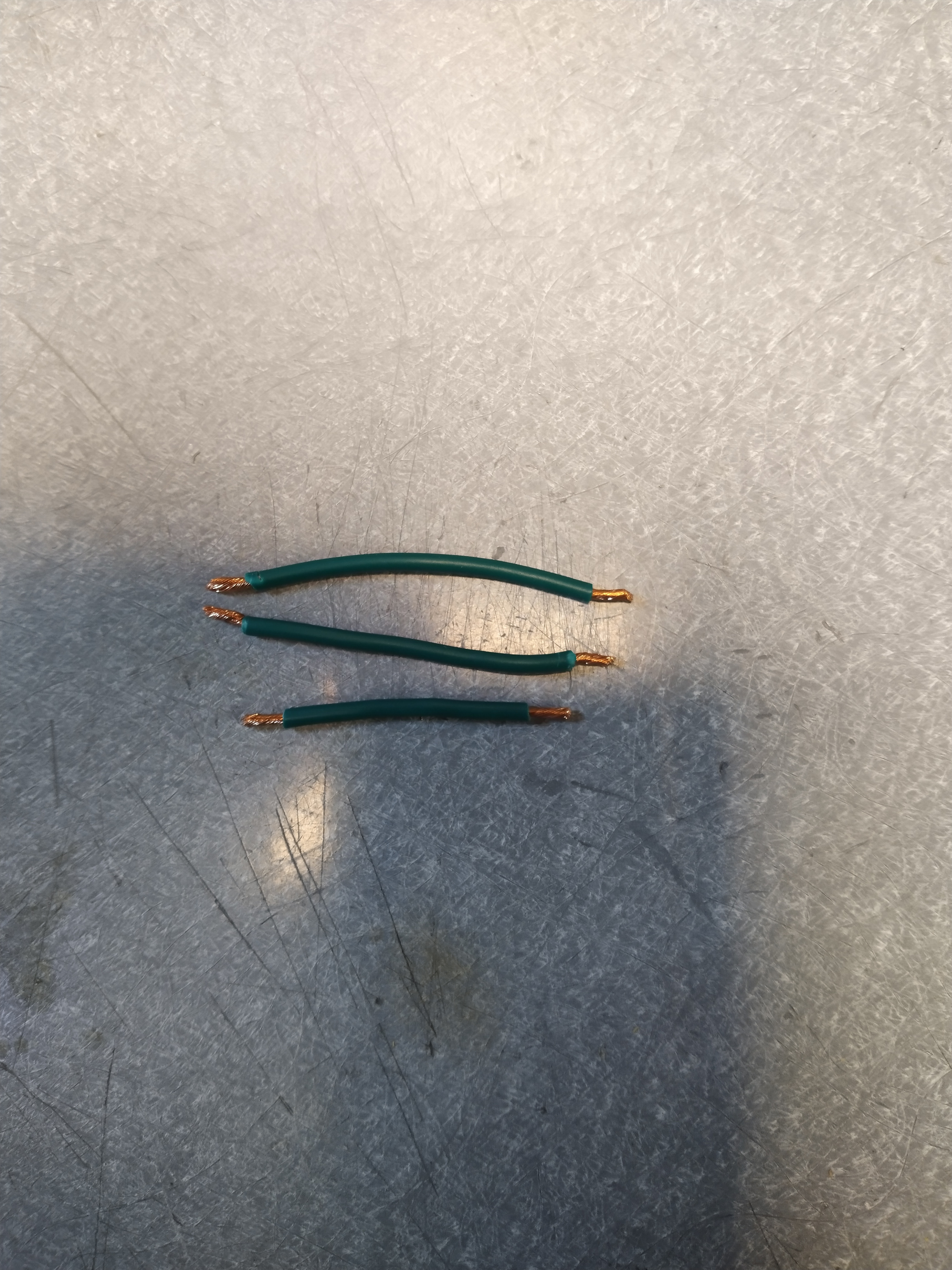
Cut and strip two 5cm cables of 1.5mm² section. Cut and strip one 4cm cable of 1.5mm² section.
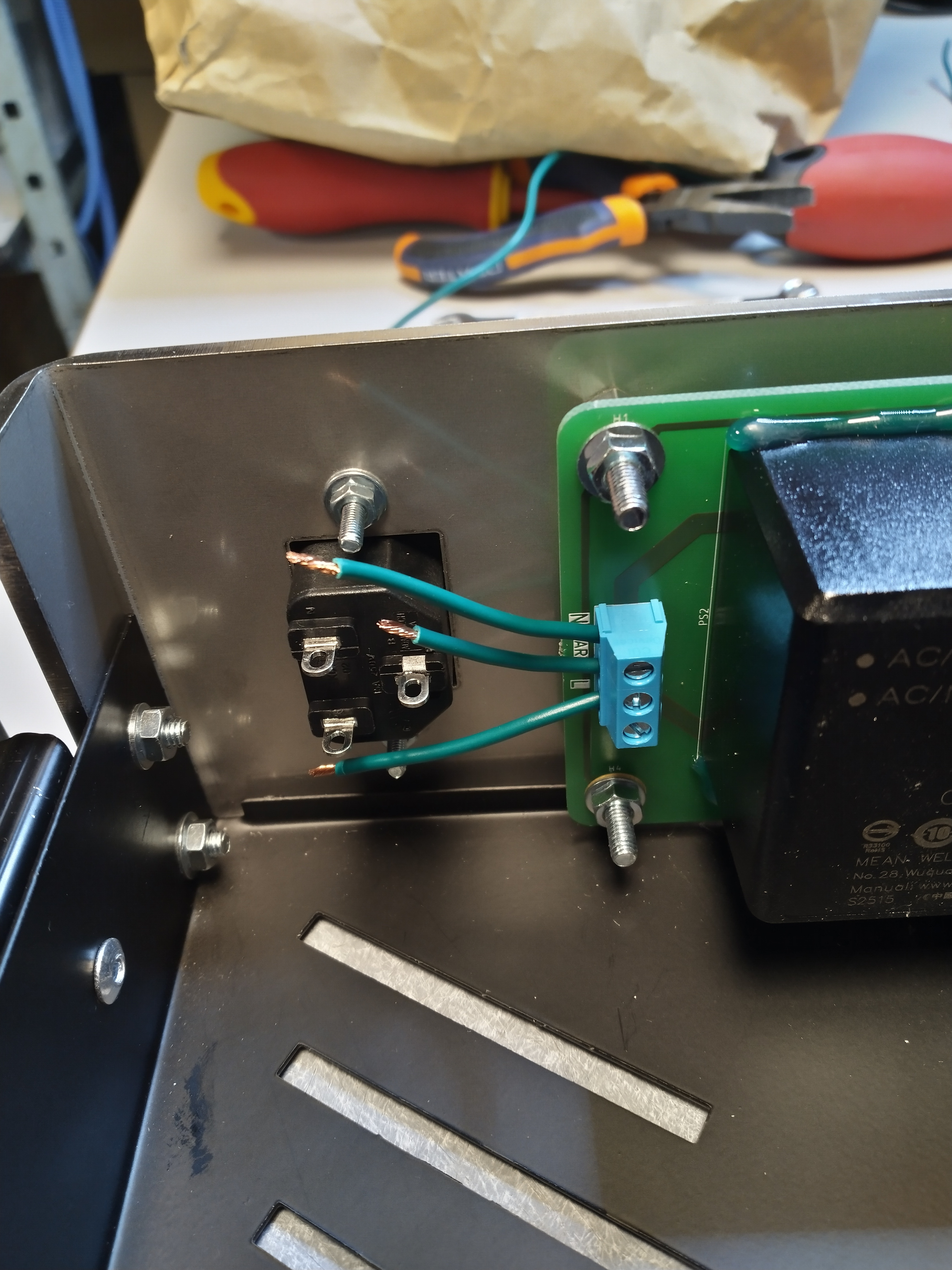
Screw the cables into the PCB power supply terminal block named J1.
The shortest cable must be located in the middle connection of the terminal block.
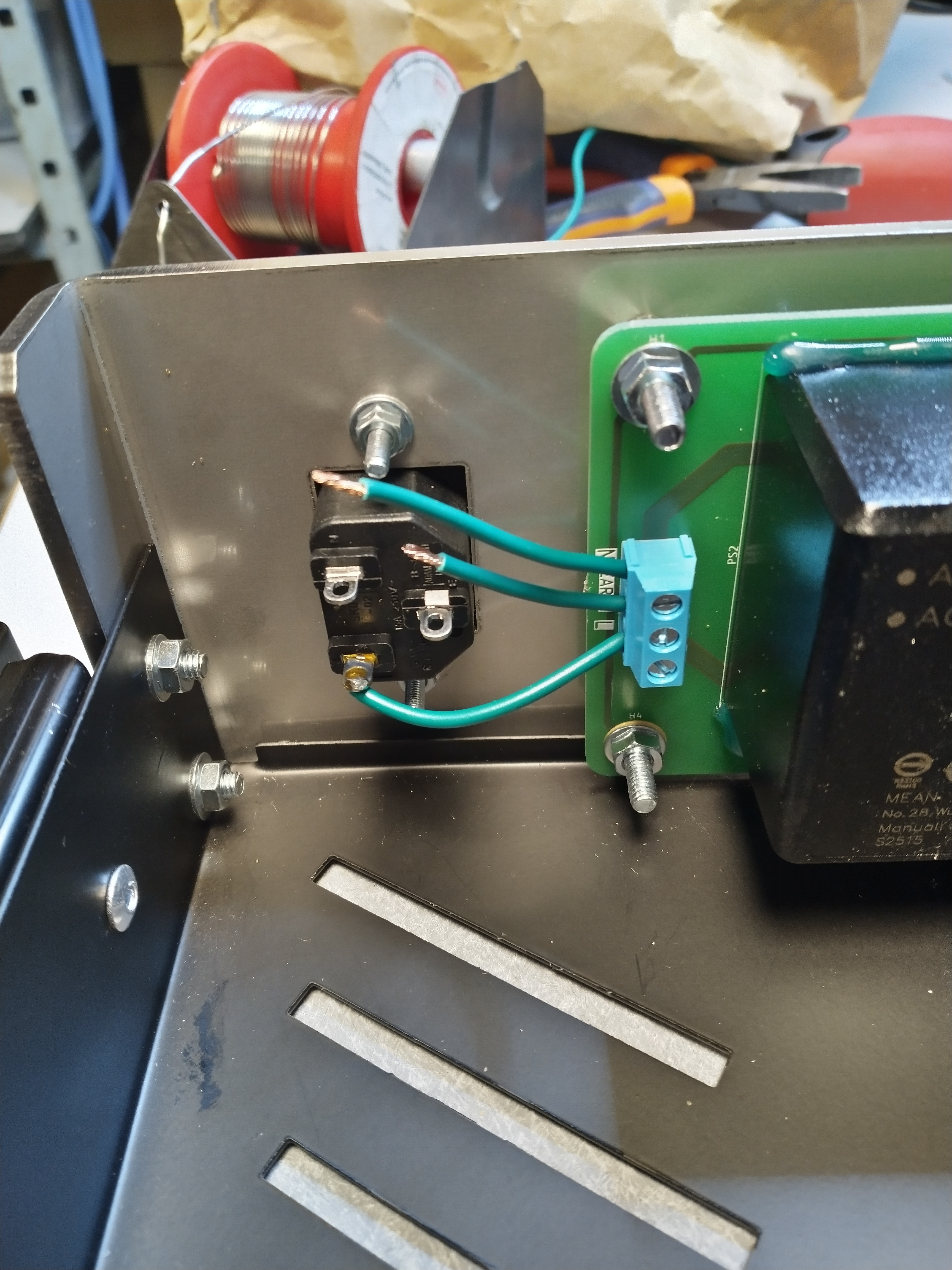
Solder all cables to the IEC terminal block.
Start from the bottom cable to ease getting access to the yet-unsoldered cables.
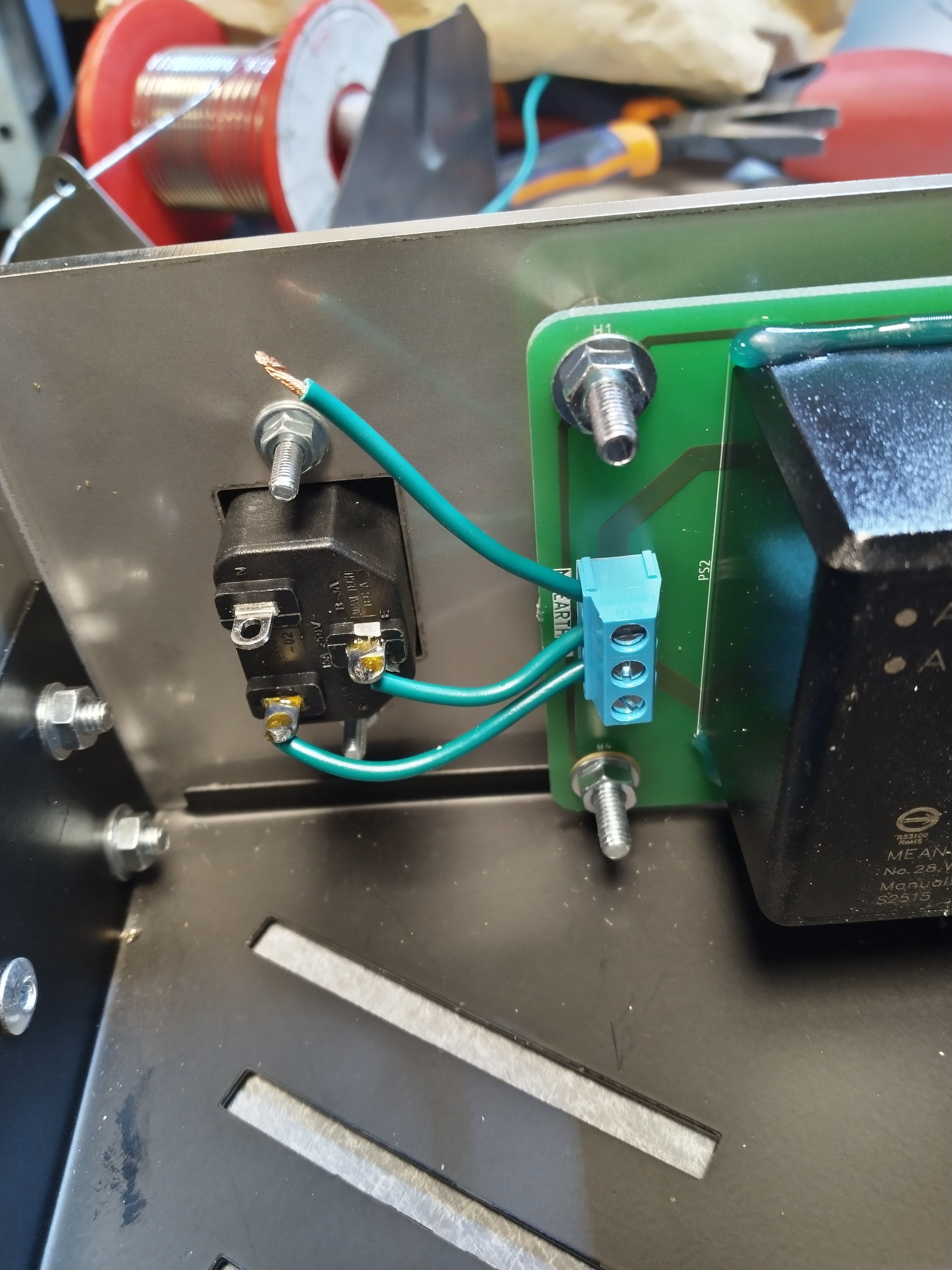
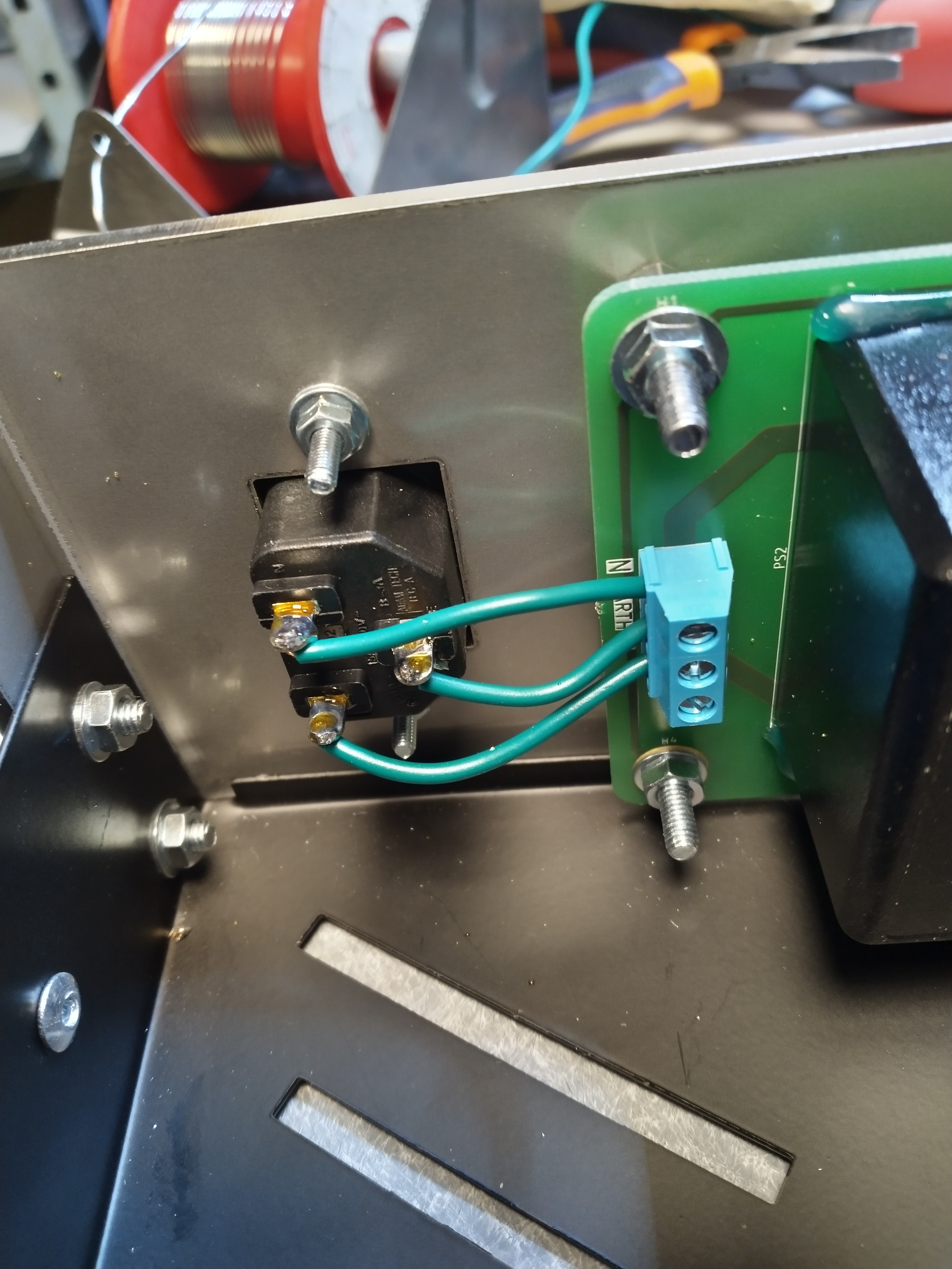
Isolate the IEC connector solder joints with hot glue, the goal is to protect an user inadvertently touching a mains conductor.
It is more effective to put the drawer with the front metal panel laying down on the table corner, so the hot glue can cover the whole solder joints.
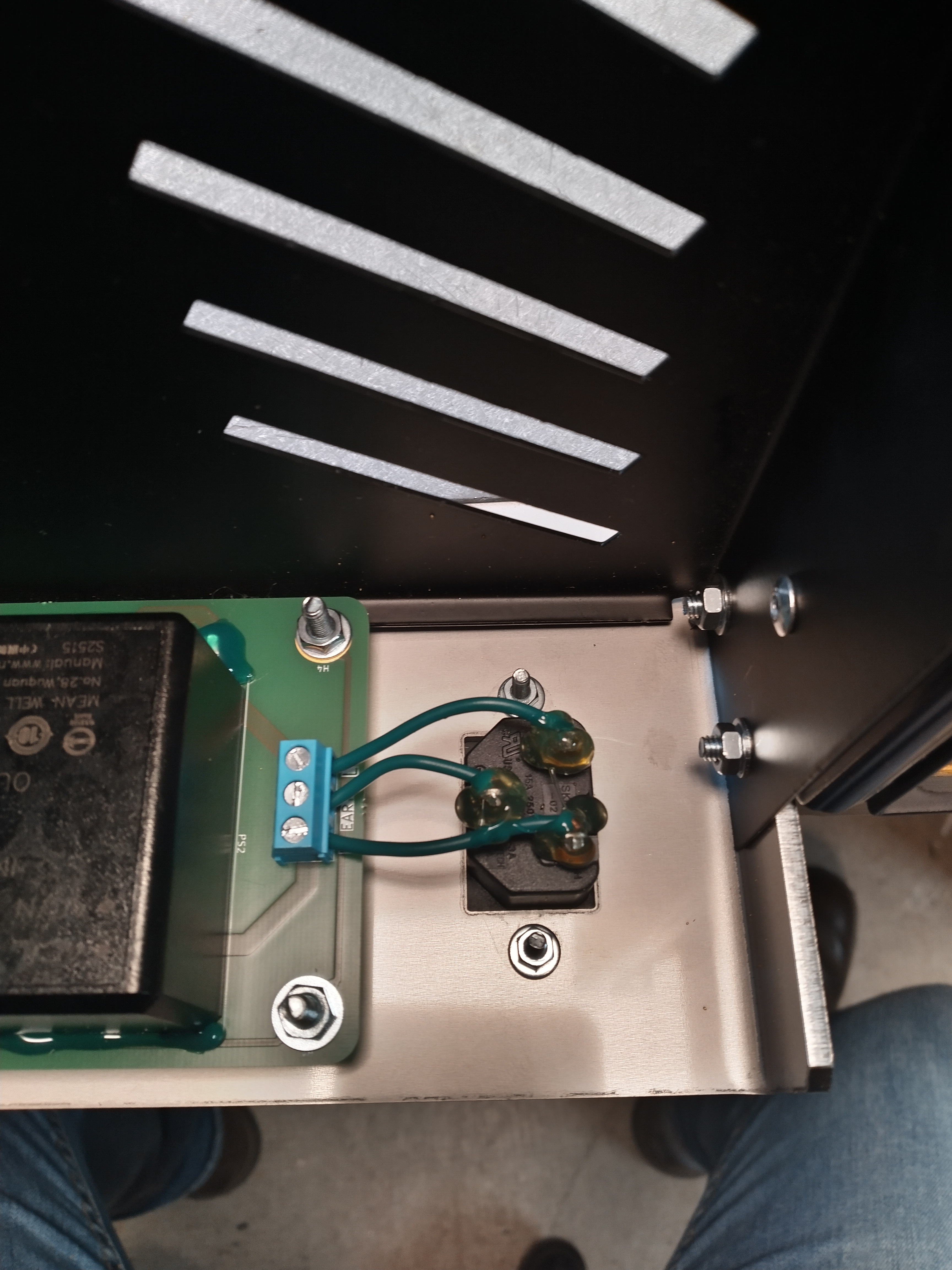
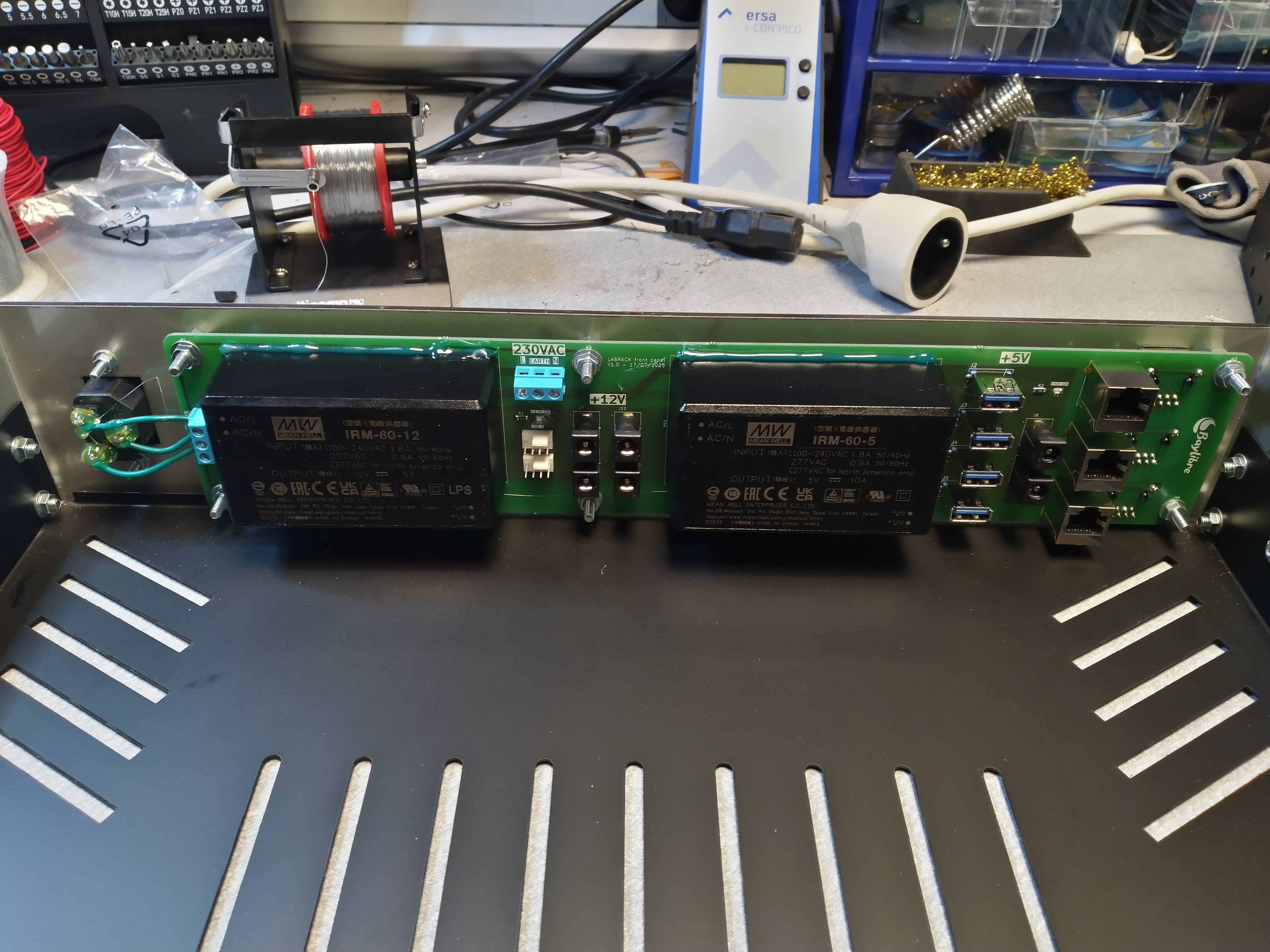
The mechanical assembly is now complete.
| Qty | Value | Footprint | References |
|---|---|---|---|
| 6 | MountingHole_Pad | MountingHole:MountingHole_4.5mm_Pad_Via | H1, H2, H3, H4, H5, H6 |
| 6 | PJ-044BH | PJ-044BH:PJ-044BH | J6, J7, J8, J9, J10, J11 |
| 6 | SS-90000-013 | Connector_RJ:RJ45_RCH_RC01937 | J12, J13, J14, J15, J16, J17 |
| 4 | USB1086 | USB1086:USB1086 | J2, J3, J4, J5 |
| 3 | 10K | Resistor_SMD:R_0603_1608Metric_Pad0.98x0.95mm_HandSolder | R4, R7, R9 |
| 3 | 10u | Capacitor_SMD:C_1210_3225Metric_Pad1.33x2.70mm_HandSolder | C1, C2, C4 |
| 2 | 150080SS75000 | LED_SMD:LED_0805_2012Metric | D1, D2 |
| 2 | 150K | Resistor_SMD:R_0603_1608Metric_Pad0.98x0.95mm_HandSolder | R3, R6 |
| 2 | 18K | Resistor_SMD:R_0603_1608Metric_Pad0.98x0.95mm_HandSolder | R5, R8 |
| 2 | 470531000 | Connector:FanPinHeader_1x04_P2.54mm_Vertical | J18, J19 |
| 2 | BSS138 | Package_TO_SOT_SMD:SOT-23 | Q1, Q2 |
| 2 | TB006-508-03BE | TB006-508:TB006-508-03BE | J1, J20 |
| 2 | UMT250-3403.0169.11 | Fuse:Fuse_Schurter_UMT250 | F1, F2 |
| 1 | 1.2K | Resistor_SMD:R_1206_3216Metric_Pad1.30x1.75mm_HandSolder | R1 |
| 1 | 100n | Capacitor_SMD:C_0603_1608Metric_Pad1.08x0.95mm_HandSolder | C3 |
| 1 | 470 | Resistor_SMD:R_1206_3216Metric_Pad1.30x1.75mm_HandSolder | R2 |
| 1 | IRM-60-12 | Converter_ACDC:Converter_ACDC_MeanWell_IRM-60-xx_THT | PS2 |
| 1 | IRM-60-5 | Converter_ACDC:Converter_ACDC_MeanWell_IRM-60-xx_THT | PS1 |
| 1 | LM393DT | Package_SO:SOIC-8_3.9x4.9mm_P1.27mm | U1 |
| 1 | LOGO | Logo_BayLibre:Logo_BayLibre | G*** |
| 1 | TBC05-02-1-G-G | TerminalBlock_Phoenix:TerminalBlock_Phoenix_MPT-0,5-2-2.54_1x02_P2.54mm_Horizontal | J21 |
It measures 350 × 70 mm and has 2 copper layers, 1.6 mm thick.
50 parts, built around the IRM-60-12, IRM-60-5, LM393DT and PJ-044BH. The full list of its parts is on this page, with links to each part's symbol and footprint where PCBKit's library has them.
From the BayLibre/Labrack repository on GitHub, at the commit this page was made from: the board is Hardware/Rack_Front_Panel.kicad_pcb and its schematic Hardware/Power_Button_Press_Automation.kicad_sch. PCBKit opens the board in the browser, with nothing to install.
Its repository states no licence, so its author keeps all rights: ask BayLibre before reusing the design.

RICCIARDI-Adrien/Power_Button_Press_Automation
A fully analog circuit to simulate a power button press.

MbFredys/PCB-LEDs-Controller
LED-controller PCB design exercise focused on PWM control, power distribution, and hardware documentation.

olexsu/inos-rev-a-robotics-controller
INOS Rev A — CAN-based robotic arm controller designed as a real-time motion-control node for NVIDIA Jetson robotics systems.

purduerov/X18-ROV-Test-Bench
This will be the place to push all test bench changes.


kyledenobel/RGA_Boards
PCB Board design and development for RGA (Recording Guitar Amplifier)

jdelgranchio/haptic-linear-slider
A PCB for a motorized, haptic linear slider. An RP2354 (RP2350 with built-in flash) drives a Bourns PSM01 motorized slide potentiometer through a DRV8876 H-bridge.