4 layers191 × 229 mm

 jimbro1000/Dragon32Rev3Proto2
SMD Prototype of Dragon32 Rev3
Dragon32 is an open-source printed circuit board by jimbro1000, from the jimbro1000/Dragon32Rev3Proto repository on GitHub, published under the MIT licence. It is a 4-layer board of 253 × 169.1 mm with 199 parts on 393 nets, routed with 4,631 tracks and 668 vias.
It is built around the 74HCT244D, 74LS373SC and CD4050BDRG, with the MAX232N, MAX3012EUP+ and 74ACT02M among its other parts. Its parts include 71 capacitors, 47 resistors, 25 ICs, 10 diodes and 6 connectors.


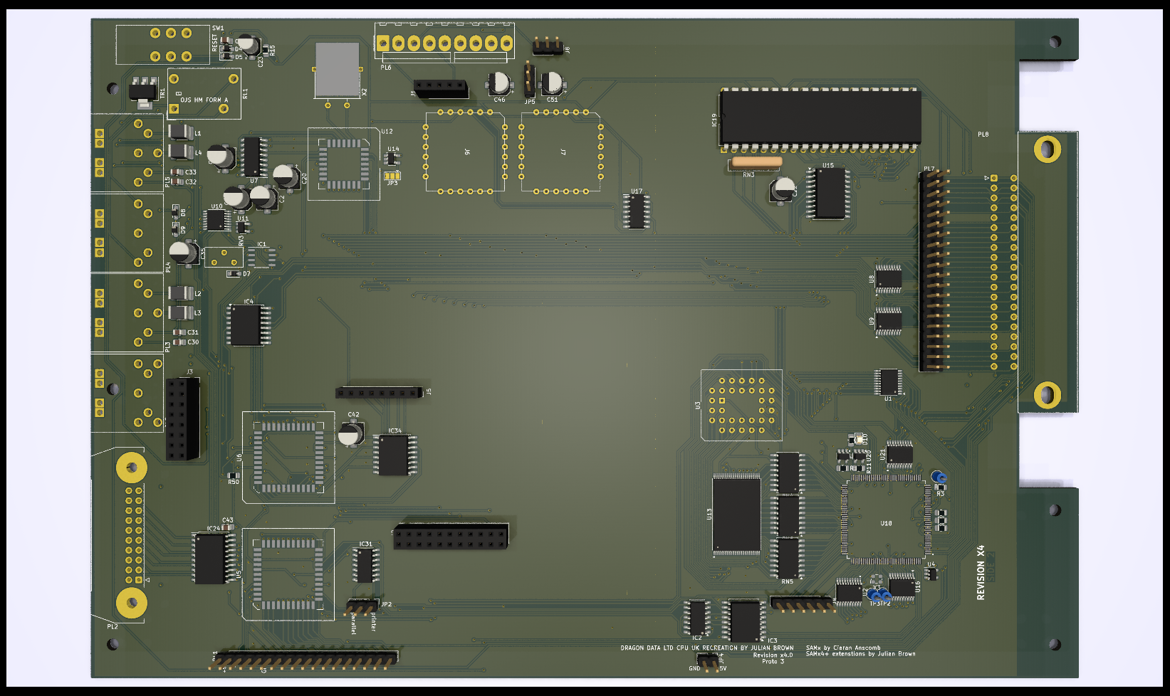
This project started as a recreation of the SA2120 CPU Mainboard for the 1982 Dragon Data Dragon 32
Everything (excluding modifications) is taken from the SA2120 schematics. Where this version changes is the move to surface mount components which radically alters the size of each part along with a move to using SRAM instead of DRAM. The intention is that the board should be supplied fully or semi-populated leaving just optional (socketed) components to be fitted.
The ROM is now a single 28C256 eprom with an option to switch between two images using JP6 or to allow the rom to be automatically selected from the PIA. In effect this allows the computer to operate as a D32 but with two different images or as a D64.
The video circuits have been isolated from the rest of the board to improve output quality.
To maintain compatibility with the D64 there is an optional serial port. This needs to be enabled by bridging a solder jumper (JP3) to position 1-2. If the serial port is not being populated it should be position 2-3. By default this is not bridged and the computer will not function without the jumper being set. If the supporting SMD ICs at U13 and U14 are fitted the jumper can safely be left in position 1-2 regardless of whether the 6551 UART chip is fitting.
If you are fitting the board into an early D32 case the serial port would be completely covered without modifying the case. Later D32 cases had all four ports but the fourth (serial) port blanked off internally.
A second (internal) cartridge port has been added, by way of a 2x20 header, along with an additional +5V/Gnd pickup point for further internal expansion. The keyboard connector also has two additional pins that can supply 5v to the keyboard, the extra pins are on the left. The keyboard should always be fitted to the right to avoid any shorts.
The board incorporates a replacement to the SAM chip based on Ciaran Anscomb's SAMx4 design which in turn includes Stewart Orchards 256k banker board https://gitlab.com/sorchard001/dragon-256k-banker-board
A custom VHDL is needed for this. Do not use the code from Ciaran's site as it won't work.
The VHDL has potential (untried as of yet) to allow the board to run permanently at double speed without loss of a working display. The potential extends to running at 4x speed but this is subject to using a suitable CPU and SRAM.
Because all of the CPU speed control is managed by the CPLD replacing the SAM it is possible to change and update the VHDL programming to include new features provided they do not need changes to the board itself. Running at x4 speed would require a different oscillator at X1 but would not need other changes. All of the specified components are modern high performance equivalents and should be easily able to cope with the high clock frequencies.
The board also includes three PIAs but only the first two are necessary for normal usage. The third PIA (U7) is used by some of the video daughterboards to provide additional functionality such as a programmable character "rom".
All of the PIAs are changed to the W65C21 chip instead of the MC6821. These chips work at higher frequencies and conveniently use a smaller PLCC package
In the current state (3.0) only the basics of the board have been tested and proven.
To be tested:
The two joystick ports provide a second fire button capability wired to consecutive keyboard rows, as per the Tandy CoCo. Unless a two button joystick is used this make no difference to the operation of the computer. It also requires the use of 6-pin DIN sockets, these are pin compatible with the 5-pin originals so a regular single button joystick can still be used.
The two extra buttons can also be disabled by omitting L3 and L4.
A jumper (JP2) has been introduced to bypass the logic inverter on the STROBE line. When bypassed the parallel port should operate as a communication port for DRIVEWIRE.
The board is configurable between 32k and 64k ram addressing using jumper JP1. In most scenarios there is no reason to disable the 64k option.
One of the possible features of the board is to support an extended version of the video circuitry to include external character ram. Adding a third PIA to the board takes a little refinement of how PIAs are interfaced. In this case the mapped memory for PIA1 is broken into 8 blocks, this first maps to the original memory space for PIA1 while the other 7 are effectively available to more registers. On this board only the first of those 7 is used (yet). This makes addresses $FF44-$FF47 map to the new PIA (referenced here as 1b).
Register A of PIA1b is control of additional functions
bit 0 controls internal or external character image generation
bit 1 controls automatic invert on bit 6 of the data bus
bit 2 is manual control of the invert signal
bit 3 controls automatic semigraphics on bit 7 of the data bus
bit 4 is manual control of the semigraphics signal
bit 5 opens the external character ram to writing
bit 6 is a clock trigger to the external character ram address
bit 7 is unused (proposed to be CoCo compatibility switch for
the keyboard)
Register B of PIA1b is used for programming the external character ram data.
The external character ram can only be programmed while the video is set to the internal character data of the 6847.
The board includes the serial port capability originally added to the D64. This adds a dedicated 6551 UART chip to the machine allowing serial communications at higher speeds without locking out the CPU. The port is optional.
To allow this to work the board must user a D64 power board that supplies -12V instead of -5V. It is possible to rig the board to work by bridging two pins (2 and 3) of REG1 but this is not the intended mode of operation. If the board is rigged for -5V supply then REG1, C18 and C19 must be left unpopulated.
All of the components specified with the exception of the CPU are current and should be readily available. Supplies of 6809 CPUs are still plentiful but are all NOS.
The Hitachi HD6309 is usable but may cause crashes in some software due to lazy coding. It is however still made thanks to usage in old military equipment in at least one country.
The board may look empty in its current form but the design is dominated by the main data and address busses.
The design will also include two AY8912 audio chips to provide stereo sound. This brings utilisation of the additional device addressing to 50% but also fills up the remainder of the board.
It is possible to increase the size of the board along the bottom edge as the current design complies with the original D32 design rather than the enlarged D64 board.
| Qty | Value | Footprint | References |
|---|---|---|---|
| 14 | 4.7uF | Capacitor_SMD:C_0805_2012Metric_Pad1.18x1.45mm_HandSolder | C12, C13, C14, C15, C16, C17, C18, C19, C28, C37, C49, C50, C54, C55 |
| 14 | 4K7 | Resistor_SMD:R_0805_2012Metric_Pad1.20x1.40mm_HandSolder | R2, R6, R7, R9, R12, R13, R14, R28, R30, R32, R38, R44, R53, R63 |
| 13 | 0.1uF | Capacitor_SMD:C_0805_2012Metric_Pad1.18x1.45mm_HandSolder | C3, C4, C5, C6, C7, C8, C9, C11, C27, C36, C47, C76, C77 |
| 11 | 1K | Resistor_SMD:R_0805_2012Metric_Pad1.20x1.40mm_HandSolder | R8, R34, R49, R65, R66, R67, R68, R72, R73, R74, R75 |
| 10 | 0.47uF | Capacitor_SMD:C_0805_2012Metric_Pad1.18x1.45mm_HandSolder | C25, C29, C34, C40, C41, C52, C56, C57, C58, C59 |
| 9 | 1N914 | Diode_SMD:D_SOD-323_HandSoldering | D1, D2, D3, D4, D5, D6, D7, D8, D9 |
| 8 | 0.01uF | Capacitor_SMD:C_0805_2012Metric_Pad1.18x1.45mm_HandSolder | C1, C38, C39, C43, C45, C60, C68, C69 |
| 6 | 10K | Resistor_SMD:R_0805_2012Metric_Pad1.20x1.40mm_HandSolder | R10, R11, R31, R42, R43, R56 |
| 5 | 1u | Capacitor_SMD:C_0805_2012Metric_Pad1.18x1.45mm_HandSolder | C61, C62, C63, C66, C67 |
| 5 | 22nF | Capacitor_SMD:C_0805_2012Metric_Pad1.18x1.45mm_HandSolder | C30, C31, C32, C33, C44 |
| 4 | 10u | Capacitor_SMD:CP_Elec_5x5.3 | C2, C20, C21, C24 |
| 4 | 3.3uH | Inductor_SMD:L_1812_4532Metric_Pad1.30x3.40mm_HandSolder | L1, L2, L3, L4 |
| 4 | MAX3012 | Package_SO:TSSOP-20_4.4x6.5mm_P0.65mm | U1, U2, U16, U21 |
| 3 | 22R | Package_SO:SOIC-16W_5.3x10.2mm_P1.27mm | RN4, RN5, RN6 |
| 2 | 100K | Resistor_SMD:R_0805_2012Metric_Pad1.20x1.40mm_HandSolder | R15, R36 |
| 2 | 100R | Resistor_SMD:R_0805_2012Metric_Pad1.20x1.40mm_HandSolder | R1, R3 |
| 2 | 100n | Capacitor_SMD:C_0805_2012Metric_Pad1.18x1.45mm_HandSolder | C10, C65 |
| 2 | 10uF | Capacitor_SMD:CP_Elec_5x5.3 | C35, C42 |
| 2 | 10uF | Capacitor_SMD:CP_Elec_5x3 | C46, C51 |
| 2 | 22R | Resistor_SMD:R_0805_2012Metric_Pad1.20x1.40mm_HandSolder | R4, R5 |
| 2 | 56K | Resistor_SMD:R_0805_2012Metric_Pad1.20x1.40mm_HandSolder | R50, R52 |
| 2 | 74ACT02 | Package_SO:SOIC-14_3.9x8.7mm_P1.27mm | IC2, IC31 |
| 2 | 74HCT244 | Package_SO:TSSOP-20_4.4x6.5mm_P0.65mm | U8, U9 |
| 2 | SN105125DBVR | Package_TO_SOT_SMD:SOT-23-5 | U19, U20 |
| 2 | W65C21 | Package_LCC:PLCC-44_SMD-Socket | U5, U6 |
| 1 | 1.8432MHz | Crystal:Crystal_HC18-U_Horizontal_1EP_style2 | X2 |
| 1 | 100uF | Capacitor_SMD:C_0805_2012Metric_Pad1.18x1.45mm_HandSolder | C53 |
| 1 | 100uF | Capacitor_SMD:CP_Elec_5x5.3 | C22 |
| 1 | 10M | Resistor_SMD:R_0805_2012Metric_Pad1.20x1.40mm_HandSolder | R33 |
| 1 | 14.31818MHz | Oscillator:Oscillator_SMD_ECS_2520MV-xxx-xx-4Pin_2.5x2.0mm | X3 |
| 1 | 15K | Resistor_SMD:R_0805_2012Metric_Pad1.20x1.40mm_HandSolder | R48 |
| 1 | 1M5 | Resistor_SMD:R_0805_2012Metric_Pad1.20x1.40mm_HandSolder | R51 |
| 1 | 1uF | Capacitor_SMD:CP_Elec_4x4.5 | C23 |
| 1 | 2.2nF | Capacitor_SMD:C_0805_2012Metric_Pad1.18x1.45mm_HandSolder | C26 |
| 1 | 220R | Resistor_SMD:R_0805_2012Metric_Pad1.20x1.40mm_HandSolder | R46 |
| 1 | 22pF | Capacitor_SMD:C_0805_2012Metric_Pad1.18x1.45mm_HandSolder | C48 |
| 1 | 2u2 | Capacitor_SMD:C_0805_2012Metric_Pad1.18x1.45mm_HandSolder | C64 |
| 1 | 33K | Resistor_SMD:R_0805_2012Metric_Pad1.20x1.40mm_HandSolder | R16 |
| 1 | 4052 | Package_SO:TSSOP-16_4.4x5mm_P0.65mm | U10 |
| 1 | 470R | Potentiometer_THT:Potentiometer_Bourns_3386X_Horizontal | RV3 |
| 1 | 4K7 | Resistor_THT:R_Array_SIP5 | RN3 |
| 1 | 5vPower | Connector_PinHeader_2.54mm:PinHeader_1x02_P2.54mm_Vertical | JP4 |
| 1 | 6-bit DAC | Connector_PinSocket_2.54mm:PinSocket_1x08_P2.54mm_Vertical | J5 |
| 1 | 68K | Resistor_SMD:R_0805_2012Metric_Pad1.20x1.40mm_HandSolder | R29 |
| 1 | 6K8 | Resistor_SMD:R_0805_2012Metric_Pad1.20x1.40mm_HandSolder | R45 |
| 1 | 74ACT138 | Package_SO:SOIC-16W_7.5x10.3mm_P1.27mm | IC4 |
| 1 | 74ACT138N | Package_SO:SOIC-16W_7.5x10.3mm_P1.27mm | IC3 |
| 1 | 74ACT244N | Package_SO:SOIC-20W_7.5x12.8mm_P1.27mm | IC24 |
| 1 | 74AHCT1G04 | Package_TO_SOT_SMD:SOT-23-5_HandSoldering | U14 |
| 1 | 74LS08 | Package_SO:SO-14_3.9x8.65mm_P1.27mm | U17 |
| 1 | 74LS373 | Package_SO:SOIC-20W_7.5x12.8mm_P1.27mm | U15 |
| 1 | 8K2 | Resistor_SMD:R_0805_2012Metric_Pad1.20x1.40mm_HandSolder | R47 |
| 1 | Audio Left | Dragon:AY-QTHT | J6 |
| 1 | Audio Right | Dragon:AY-QTHT | J7 |
| 1 | Board Interconnect Female | Connector_PinSocket_2.54mm:PinSocket_2x11_P2.54mm_Vertical | J2 |
| 1 | CD4050BDR | Package_SO:SOIC-16W_7.5x10.3mm_P1.27mm | IC34 |
| 1 | Conn_01x09_Male | Connector_Molex:Molex_KK-396_A-41791-0009_1x09_P3.96mm_Vertical | PL6 |
| 1 | Conn_01x18_Pin | Connector_PinHeader_2.54mm:PinHeader_1x18_P2.54mm_Vertical | PL1 |
| 1 | Conn_02x08_Odd_Even | Connector_PinSocket_2.54mm:PinSocket_2x08_P2.54mm_Vertical | J3 |
| 1 | DIN-5 (180) Cassette | Dragon:DIN-5_DELTRON_671-0501_45deg_Horizontal | PL4 |
| 1 | DIN-6 J/S L | Dragon:DIN-6_DELTRON_671-0601_Horizontal | PL5 |
| 1 | DIN-6 J/S R | Dragon:DIN-6_DELTRON_671-0601_Horizontal | PL3 |
| 1 | EDAC 392-040-558-201 | Dragon:Edge_2x20_P2.54mm_OvalMP | PL8 |
| 1 | EDAC 392-040-558-201 | Connector_PinHeader_2.54mm:PinHeader_2x20_P2.54mm_Vertical | PL7 |
| 1 | JTAG | Connector_PinHeader_2.54mm:PinHeader_1x06_P2.54mm_Vertical | J4 |
| 1 | Jumper_3_Open | Connector_PinHeader_2.54mm:PinHeader_1x03_P2.54mm_Vertical | JP5 |
| 1 | LED_RED | LED_SMD:LED_0805_2012Metric | D10 |
| 1 | LM393DR | Package_SO:SOP-8_3.9x4.9mm_P1.27mm | IC1 |
| 1 | LOGO | LOGO | G*** |
| 1 | MAX232 | Package_SO:SOIC-16_3.9x9.9mm_P1.27mm | U7 |
| 1 | MC6809E | Package_DIP:DIP-40_W15.24mm | IC19 |
| 1 | OJS HM FORM A | Dragon:OJS HM 10A Relay | RL1 |
| 1 | PZT2222A | Package_TO_SOT_SMD:SOT-223-3_TabPin2 | TR1 |
| 1 | Printer | Connector_IDC:IDC-Header_2x10-1MP_P2.54mm_Latch_Horizontal | PL2 |
| 1 | RESET | Dragon:Button_AlpsAlpine_SPUN190900 | SW1 |
| 1 | RMLV3216A | Package_SO:TSOP-I-48_18.4x12mm_P0.5mm | U13 |
| 1 | SST39SF040-55 | Package_LCC:PLCC-32_THT-Socket | U3 |
| 1 | SZ0 | Jumper:SolderJumper-2_P1.3mm_Bridged_Pad1.0x1.5mm | JP1 |
| 1 | SZ1 | Jumper:SolderJumper-2_P1.3mm_Open_Pad1.0x1.5mm | JP6 |
| 1 | SZ2 | Jumper:SolderJumper-2_P1.3mm_Bridged_Pad1.0x1.5mm | JP7 |
The 187 most common of 199 parts.


Mathesar/14mhz-accelerator
14MHz 68000 accelerator with 1MB fast ram for amiga 500

jimbro1000/Dragon32Rev3
This project started as a recreation of the SA2120 CPU Mainboard for the 1982 Dragon Data Dragon 32


It measures 253 × 169.1 mm and has 4 copper layers, 1.6 mm thick.
199 parts, built around the 74HCT244D, 74LS373SC, CD4050BDRG and MAX232N. The full list of its parts is on this page, with links to each part's symbol and footprint where PCBKit's library has them.
From the jimbro1000/Dragon32Rev3Proto repository on GitHub, at the commit this page was made from: the board is Dragon32.kicad_pcb and its schematic Dragon32.kicad_sch. PCBKit opens the board in the browser, with nothing to install.
Its repository publishes it under the MIT licence: you may reuse it on that licence's terms (keep the author's notice, and for a copyleft licence share your changes alike).