2 layers160 × 100 mm

 jburks/X16-Simple-Intf1
A very simple X16 to microcontroller interface.
SimpleInterface is an open-source printed circuit board by jburks, from the jburks/X16-Simple-Intf repository on GitHub. It is a 2-layer board of 65.5 × 58.4 mm with 19 parts on 84 nets, routed with 739 tracks and 96 vias.
It is built around the 74ACT245M, 74ACT00 and 74ACT02M, with the 74ACT04D, 74ACT157PC and 74AHC273D among its other parts. Its parts include 6 capacitors, 6 ICs, 4 connectors, 1 resistor and 1 transistor. It belongs with the interfaces and adapters boards of this library.


This is a proof of concept interface between the X16's 6502 bus and a modern microcontroller. This could be done much more simply with a CPLD, but in keeping with the "retro feel" of the X16, this was implement using all 74xx logic in a DIP package.
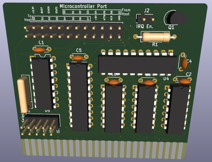
Note: The X16 card edge in the design may be mirrored. Until this can be validated, use at your own risk!
This interface contains two exposed memory addresses and three functional registers:
| Address | Name | Description |
|---|---|---|
| 0 | HOST_WR | Data byte from host to client, write only |
| 0 | HOST_RD | Data byte from client, read only |
| 1 | STATUS | Status flags for card and client, read only |
As can be seen from above, address 0 is used for both the read and write registers. The card only looks at the A0 address line which results in the HOST_XX registers appearing at all even addresses within the selected IO region and the STATUS register at all odd addresses.
The flags of the STATUS register are
| Bit | Name | Description |
|---|---|---|
| 0 | CSTAT_0 | Client status 0. This value reflects the state of the STAT_0 input pin from the client. Interpretation of the meaning of this flag is implementation dependent. |
| 1 | CSTAT_1 | Client status 1. This value reflects the state of the STAT_1 input pin from the client. Interpretation of the meaning of this flag is implementation dependent. |
| 2-5 | UNUSED | Unused status bits. Will contain the same values as the HOST_RD register. |
| 6 | BUSY | Client busy status. This bit indicates that the client has not yet acknowledged the last byte transmitted from the host. |
| 7 | ATTN | Attention. Indicates that the client is trying to get the host's attention. If jumper J2 on the card is closed, the /IRQ line will be held low (asserted) while ATTN is asserted. |
The position of the BUSY and ATTN flags is intended to allow the host software to determine their state via the BIT instruction.
The design exposes a total of 21 IO signals to a microcontroller. The direction below is specified relative to the card. "I" (Input) indicates a signal from the microcontroller to the card and "O" (Output) indicates a signal from the card to the microcontroller.
The IO signals are
| Pin | Function | Direction | Notes |
|---|---|---|---|
| H_D0 - H_D7 | Host data | O | The last byte of data sent from the host. This byte is stored in a register and does not reflect the state of the 6502 data bus. |
| C_D0 - C_D7 | Client data | I | A byte of data sent from the microcontroller to the host.This byte is not stored in a register and should be maintained by the microcontroller until it is no longer needed (as determined by the implementation). |
| ATTN | Client attention | I | Should be set high by the microcontroller to indicate that it wants the host's attention. The pin state should be maintained by the microcontroller until host attention is no longer needed. |
| BUSY | Host attention | O | Indicates that the host has written a byte to the HOST_WR register that the microcontroller has not acknowledged. The card is reporting to the host that the microcontroller is busy. |
| ACK | Acknowledge | I | A strobe on this pin by the microcontroller will clear the BUSY signal. This pin should not be held high, asserting it for ~10ns is sufficient. |
| STAT_0 - STAT_1 | Status 0/1 | I | Implementation-dependent status signals. The state of these inputs can be read by the host in the CSTAT_0 and CSTAT_1 flags of the STATUS register. |
| Qty | Value | Footprint | References |
|---|---|---|---|
| 6 | 1uF | Capacitor_THT:C_Disc_D4.3mm_W1.9mm_P5.00mm | C1, C2, C3, C4, C5, C6 |
| 1 | 25K | Resistor_THT:R_Array_SIP5 | RN1 |
| 1 | 74ACT00 | Package_DIP:DIP-14_W7.62mm | U2 |
| 1 | 74ACT02 | Package_DIP:DIP-14_W7.62mm | U3 |
| 1 | 74ACT04 | Package_DIP:DIP-14_W7.62mm | U1 |
| 1 | 74ACT157 | Package_DIP:DIP-16_W7.62mm | U5 |
| 1 | 74ACT245 | Package_DIP:DIP-20_W7.62mm | U6 |
| 1 | 74AHC273 | Package_DIP:DIP-20_W7.62mm | U4 |
| 1 | BS170 | Package_TO_SOT_THT:TO-92_Inline | Q1 |
| 1 | DNP | Resistor_THT:R_Axial_DIN0309_L9.0mm_D3.2mm_P12.70mm_Horizontal | R1 |
| 1 | IO Select | Connector_PinHeader_2.54mm:PinHeader_2x05_P2.54mm_Vertical | J1 |
| 1 | IRQ Enable | Connector_PinHeader_2.54mm:PinHeader_2x01_P2.54mm_Vertical | J2 |
| 1 | Microcontroller Port | Connector_PinHeader_2.54mm:PinHeader_2x12_P2.54mm_Vertical | J3 |
| 1 | X16_Card_Edge | X16:X16_Card_Edge | P1 |


misterblack1/cga2rgb
A board to convert digital RGB signals to analog RGB with easily available parts


tmarhguy/tomato
A functional 32-bit computer built from scratch in a dorm; implemented on FPGA, Kicad, browser simulation

Mathesar/14mhz-accelerator
14MHz 68000 accelerator with 1MB fast ram for amiga 500

rekursiv/stepperature
Stepperature is a DIY, Open Hardware, Manual Pulse Generator (Quadrature) hand wheel interface for CNC, audio, or other projects.

Dethernal/Midibox3
New features for DIN5 MIDI → Waweblaster interface board. Now with MT-32 stuff.
It measures 65.5 × 58.4 mm and has 2 copper layers, 1.6 mm thick.
19 parts, built around the 74ACT245M, 74ACT00, 74ACT02M and 74ACT04D. The full list of its parts is on this page, with links to each part's symbol and footprint where PCBKit's library has them.
From the jburks/X16-Simple-Intf repository on GitHub, at the commit this page was made from: the board is pcb/SimpleInterface.kicad_pcb and its schematic pcb/SimpleInterface.kicad_sch. PCBKit opens the board in the browser, with nothing to install.
Its repository states no licence, so its author keeps all rights: ask jburks before reusing the design.