4 layers10.7 × 20.8 mm

 jimbro1000/DragonRev3.5
CPLD/FPGA core based Dragon PCB
Dragon32Rev3.5 is an open-source printed circuit board by jimbro1000, from the jimbro1000/DragonRev3.5 repository on GitHub. It is a 2-layer board of 253 × 199.4 mm with 156 parts on 341 nets, routed with 3,080 tracks and 375 vias.
It is built around the SLG46824V, CD4050BDRG and MAX3232ID, with the 74LVC1G3157, 74AHCT1G08SE and 74LS04PC among its other parts. Its parts include 40 resistors, 35 ICs, 33 capacitors, 8 diodes and 8 connectors. It belongs with the fPGA and programmable logic boards of this library.


This project contains the design for a hugely upgraded version of the Dragon 32 (technically a Dragon 64 for pedants)
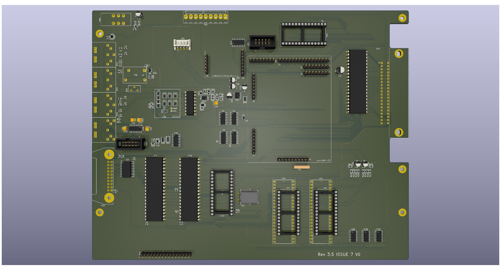
The basis of the design is the Dragon 32 recreation that I have been refining for some time. The peripheral IO remains as originally specified by Dragon Data but the ram, address multiplexer and video display generator or implemented on a separate plug-in component.
Technically the original ICs could be implemented on the plug-in and you would be left with an original piece of hardware (in terms of function). I already have a board for that though...
The benefit of the plugin board is to implement the complex (and expensive) fabrication on a smaller device and abstract away the upgrades that are contained.
Almost every passive component and supporting logic ICs have been switched to surface mount technology. This means the board can be part assembled at relatively low cost, leaving just the major ICs, ports, connectors and relay to be hand assembled.
The main board replicates the footprint of the original D64 PCB. Ports and fixings are all in their original positions.
The CPU lives on the main board with any speed variant supported including the HD63C09. The onboard ROM is integrated into a single chip holding both banks of the D64 ROM image.
All IO (except video) is performed by the original hardware so the two PIAs and UART are retained.
The device select signals for peripherals has been disambiguated from two devices which repeat the same four addresses eight times, to sixteen devices, each with four mapped addresses.
These three blocks maintain compatibility with the original ROM software.
The other blocks (P0c-P0g and P1b-P1g) are unused and can be adopted for other hardware (see audio)
The core board provides RAM, Video and SAM functionality. The minimum version of this would be the original RAM, VDG and SAM chips which effectively reproduces the original D64 specification.
At this time two upgrade core boards exist. The first is a mild upgrade that provides 2MB of RAM, a SAMx implementation and an upgraded VDG that replicates the video functionality of the CoCo3 GIME chip
The second core board provides all of the capabilities of the first board but adds a soft 6809 CPU that can operate alongside or instead of the CPU on the main board. This second CPU can operate at much higher speeds than the original, match the speed of the original or be completely disabled. When both CPUs are operating the second CPU can be completely detached from everything except RAM and running on an independent clock cycle, or it can share the full bus with the hardware CPU utilising the bus mastering signals.
The second core also introduces a DMA capability that enables very fast memory copy actions, running independently of either CPU.
The video capabilities of the second core add sprite handling and tile based video modes, all in a layered video system that allows tiles, bitmaps and sprites to exist on the same display.
For details of the core implementations see the separate hardware and firmware repositories.
The main board will (but does not currently) provide a socket for an audio upgrade. The proposal is to utilise four or six peripheral address blocks to provide an interface to the audio board. Each block effectively represents a single audio device.
The multi device approach should allow the audio board to generate a rich stereo output with multiple audio waveforms per stereo channel.
Optionally I want to look at live mixing of the audio to allow user selection of which waveform ends up on which channel. This would likely consume another peripheral address block.
Following this approach would permit the use of original sound generator chips but has the problem of identifying the source of interrupts.
An alternative is to define a soft audio generator in a MCU or CPLD that focuses all of the IO into a single hardware device (possibly still using multiple peripheral IO blocks) but potentially makes the hardware interface non-standard. If a suitable open source firmware definition can be identified, this is likely to be the better option.
An example of this would be the YM2149 PSG System that implements a simulation of dual YM2149s (or AY-3-8910s) with stereo mixer and bass and treble controls.
Due to the limited external IO required this could be implemeted on a relatively cheap, modest FPGA device rather than the main core board which requires a significant level of IO connectivity.
The two joystick ports provide a second fire button capability wired to consecutive keyboard rows, as per the Tandy CoCo. Unless a two button joystick is used this make no difference to the operation of the computer. It also requires the use of 6-pin DIN sockets, these are pin compatible with the 5-pin originals so a regular single button joystick can still be used.
The two extra buttons can also be disabled by omitting L3 and L4
This project and all its hardware design are licensed under creative commons CC BY-NC 4.0
You are free to:
Share - copy and redistribute the material in any medium or format
Adapt - remix, transform, and build upon the material
The licensor cannot revoke these freedoms as long as you follow the license terms.
Under the following terms:
Attribution - You must give appropriate credit, provide a link to the license, and indicate if changes were made. You may do so in any reasonable manner, but not in any way that suggests the licensor endorses you or your use.
NonCommercial - You may not use the material for commercial purposes.
| Qty | Value | Footprint | References |
|---|---|---|---|
| 11 | 4K7 | Resistor_SMD:R_0402_1005Metric | R3, R4, R5, R8, R9, R11, R13, R14, R15, R17, R32 |
| 8 | 1N914 | Diode_SMD:D_SOD-523 | D1, D2, D3, D4, D5, D6, D7, D8 |
| 8 | 74LVC1G3157 | PCM_Package_TO_SOT_SMD_AKL:SOT-363_SC-70-6 | U6, U7, U8, U9, U10, U11, U12, U13 |
| 7 | 10000pF | Capacitor_SMD:C_0603_1608Metric | C3, C5, C6, C7, C8, C9, C13 |
| 6 | 10uF | Capacitor_SMD:CP_Elec_4x3 | C18, C19, C22, C23, C25, C29 |
| 5 | 22nF | Capacitor_SMD:C_0603_1608Metric | C14, C15, C16, C33, C44 |
| 5 | ~ | MountingHole:MountingHole_3.2mm_M3_Pad | M1, M3, M4, M7, M8 |
| 4 | 10u | Capacitor_Tantalum_SMD:CP_EIA-3528-21_Kemet-B | C17, C20, C21, C24 |
| 4 | 1K | PCM_Resistor_SMD_AKL:R_0603_1608Metric | R24, R25, R49, R54 |
| 4 | 2.2K | PCM_Resistor_SMD_AKL:R_0603_1608Metric | R18, R20, R21, R23 |
| 4 | 3.3uH | Inductor_SMD:L_0805_2012Metric | L1, L2, L3, L4 |
| 4 | 4K | PCM_Resistor_SMD_AKL:R_0603_1608Metric | R19, R22, R26, R27 |
| 3 | 0.1uF | Capacitor_SMD:C_0805_2012Metric | C4, C27, C28 |
| 3 | 10K | Resistor_SMD:R_0603_1608Metric | R6, R7, R12 |
| 3 | 74ALS138N | Package_SO:SOIC-16_3.9x9.9mm_P1.27mm | U2, U3, U4 |
| 2 | 100K | Resistor_SMD:R_0402_1005Metric | R1, R2 |
| 2 | 100nF | Capacitor_SMD:C_0402_1005Metric | C10, C11 |
| 2 | 56K | PCM_Resistor_SMD_AKL:R_0603_1608Metric | R50, R52 |
| 2 | 74LVC1G66DSF | PCM_Package_TO_SOT_SMD_AKL:SOT-353_SC-70-5 | U14, U15 |
| 2 | AY-3-8910 | Package_DIP:DIP-40_W15.24mm_Socket | IC5, IC6 |
| 2 | AY-3-8912 | Package_DIP:DIP-28_W15.24mm_Socket | IC7, IC8 |
| 2 | MC6821 | Package_DIP:DIP-40_W15.24mm | IC2, IC35 |
| 2 | TestPoint_Small | TestPoint:TestPoint_Pad_D1.0mm | scl1, sda1 |
| 1 | 0.01uF | Capacitor_SMD:C_0603_1608Metric | C12 |
| 1 | 1.1K x 4 | PCM_Resistor_SMD_AKL:R_Array_Convex_4x0603 | RN3 |
| 1 | 1.8432MHz | Crystal:Crystal_HC49-U_Horizontal_1EP_style2 | XL1 |
| 1 | 100R | PCM_Resistor_SMD_AKL:R_1206_3216Metric | R10 |
| 1 | 100uF | Capacitor_SMD:CP_Elec_5x5.3 | C2 |
| 1 | 10K | PCM_Resistor_SMD_AKL:R_0805_2012Metric | R55 |
| 1 | 10M | PCM_Resistor_SMD_AKL:R_1206_3216Metric | R53 |
| 1 | 10uF | Capacitor_Tantalum_SMD:CP_EIA-3528-21_Kemet-B | C35 |
| 1 | 15K | Resistor_SMD:R_0603_1608Metric | R48 |
| 1 | 1M5 | Resistor_SMD:R_0805_2012Metric | R51 |
| 1 | 1uF | Capacitor_SMD:CP_Elec_4x4.5 | C1 |
| 1 | 2.2K x 8 | PCM_Resistor_SMD_AKL:R_Array_Convex_8x0602 | RN2 |
| 1 | 2.2nF | Capacitor_SMD:C_0603_1608Metric | C26 |
| 1 | 220R | PCM_Resistor_SMD_AKL:R_0603_1608Metric | R46 |
| 1 | 22R | PCM_Resistor_SMD_AKL:R_Array_Convex_4x0603 | RN4 |
| 1 | 22pF | Capacitor_SMD:C_0603_1608Metric | C48 |
| 1 | 28C256 | Package_DIP:DIP-28_W15.24mm_Socket | U19 |
| 1 | 33K | PCM_Resistor_SMD_AKL:R_0603_1608Metric | R16 |
| 1 | 470R | Potentiometer_THT:Potentiometer_Bourns_3386X_Horizontal | RV3 |
| 1 | 4x4K7 | Resistor_THT:R_Array_SIP5 | RN1 |
| 1 | 6551 | Package_DIP:DIP-28_W15.24mm_Socket | IC11 |
| 1 | 68K | PCM_Resistor_SMD_AKL:R_0805_2012Metric | R29 |
| 1 | 6K8 | PCM_Resistor_SMD_AKL:R_0603_1608Metric | R45 |
| 1 | 74AHCT1G08 | Package_TO_SOT_SMD:SOT-353_SC-70-5 | U1 |
| 1 | 74ALS02 | Package_SO:SOIC-16_3.9x9.9mm_P1.27mm | U5 |
| 1 | 74LS04 | Package_SO:SOIC-14_3.9x8.7mm_P1.27mm | IC39 |
| 1 | 74LS08 | Package_SO:SOIC-14_3.9x8.7mm_P1.27mm | IC38 |
| 1 | 74LS244N | Package_SO:SOIC-20W_7.5x12.8mm_P1.27mm | IC3 |
| 1 | 74LS93 | Package_SO:SOIC-14_3.9x8.7mm_P1.27mm | U20 |
| 1 | 8K2 | PCM_Resistor_SMD_AKL:R_0603_1608Metric | R47 |
| 1 | AddressBus | Connector_PinHeader_2.54mm:PinHeader_1x16_P2.54mm_Vertical | J3 |
| 1 | AudioOut | Connector_PinHeader_2.54mm:PinHeader_1x08_P2.54mm_Vertical | J8 |
| 1 | BusService | Connector_PinHeader_2.54mm:PinHeader_1x10_P2.54mm_Vertical | J7 |
| 1 | CD4050BDR | Package_SO:SOIC-16_3.9x9.9mm_P1.27mm | IC34 |
| 1 | CD4077 | Package_SO:SOIC-16_3.9x9.9mm_P1.27mm | U17 |
| 1 | ControlIn | Connector_PinHeader_2.54mm:PinHeader_1x08_P2.54mm_Vertical | J5 |
| 1 | ControlOut | Connector_PinHeader_2.54mm:PinHeader_1x08_P2.54mm_Vertical | J4 |
| 1 | DIN-5 (180) Cassette | Dragon:DIN-5_DELTRON_671-0501_45deg_Horizontal | PL4 |
| 1 | DIN-6 J/S L | Dragon:DIN-6_DELTRON_671-0601_Horizontal | PL5 |
| 1 | DIN-6 J/S R | Dragon:DIN-6_DELTRON_671-0601_Horizontal | PL3 |
| 1 | DataBus | Connector_PinHeader_2.54mm:PinHeader_1x08_P2.54mm_Vertical | J1 |
| 1 | Dragon Keyboard | Connector_PinHeader_2.54mm:PinHeader_1x16_P2.54mm_Vertical | PL1 |
| 1 | EDAC 392-040-558-201 | Dragon:Edge_2x20_P2.54mm_OvalMP | PL7 |
| 1 | External Serial | Connector_IDC:IDC-Header_2x05_P2.54mm_Vertical | J11 |
| 1 | LM393P | Package_SO:TSSOP-8_4.4x3mm_P0.65mm | IC25 |
| 1 | MAX3232 | Package_SO:SOIC-16_3.9x9.9mm_P1.27mm | U18 |
| 1 | MC14529B | Package_DIP:DIP-16_W7.62mm | IC4 |
| 1 | MC6809E | Package_DIP:DIP-40_W15.24mm | IC1 |
| 1 | OJS HM FORM A | Dragon:OJS HM 10A Relay | RL1 |
| 1 | PCM1754DBQ | Package_SO:SSOP-16_3.9x4.9mm_P0.635mm | U21 |
| 1 | Power Board Interconnect | Connector_Molex:Molex_KK-396_A-41791-0009_1x09_P3.96mm_Vertical | PL6 |
| 1 | Printer | Connector_IDC:IDC-Header_2x10-1MP_P2.54mm_Latch_Horizontal | PL2 |
| 1 | RESET | Dragon:Button_AlpsAlpine_SPUN190900 | SW1 |
| 1 | RGBS Interface | Connector_IDC:IDC-Header_2x05_P2.54mm_Vertical | J10 |
| 1 | SLG46824V | Package_DFN_QFN:Renesas_UQFN-20_2x3mm_P0.4mm_LayoutBorder4x6y | U16 |
| 1 | SS8050 | Package_TO_SOT_SMD:SOT-23-3 | Q1 |
| 1 | Serial | Dragon:DIN-7_DELTRON_671-0701_Horizontal | PL8 |
The 152 most common of 156 parts.

jimbro1000/Dragon32Rev3
This project started as a recreation of the SA2120 CPU Mainboard for the 1982 Dragon Data Dragon 32


RetroStack/TRS-80-Model-I-G-E1
Hardware Replica of the TRS-80 Model I Revision G

It measures 253 × 199.4 mm and has 2 copper layers, 1.6 mm thick.
156 parts, built around the SLG46824V, CD4050BDRG, MAX3232ID and 74LVC1G3157. The full list of its parts is on this page, with links to each part's symbol and footprint where PCBKit's library has them.
From the jimbro1000/DragonRev3.5 repository on GitHub, at the commit this page was made from: the board is Dragon32Rev3.5.kicad_pcb and its schematic Dragon32Rev3.5.kicad_sch. PCBKit opens the board in the browser, with nothing to install.
Its repository states no licence, so its author keeps all rights: ask jimbro1000 before reusing the design.