2 layers253 × 199.4 mm

 jimbro1000/Dragon32Rev33
This project started as a recreation of the SA2120 CPU Mainboard for the 1982 Dragon Data Dragon 32
Dragon32 is an open-source printed circuit board by jimbro1000, from the jimbro1000/Dragon32Rev3 repository on GitHub, published under the MIT licence. It is a 2-layer board of 253 × 169.1 mm with 171 parts on 261 nets, routed with 4,819 tracks and 960 vias.
It is built around the MAX3232ID, 27C256-17/J and 74ACT138PC, with the 74LS04PC, 74LS132P-E and LM393P among its other parts. Its parts include 55 resistors, 42 capacitors, 28 ICs, 9 diodes and 4 inductors. It belongs with the FPGA and CPLD boards of this library.


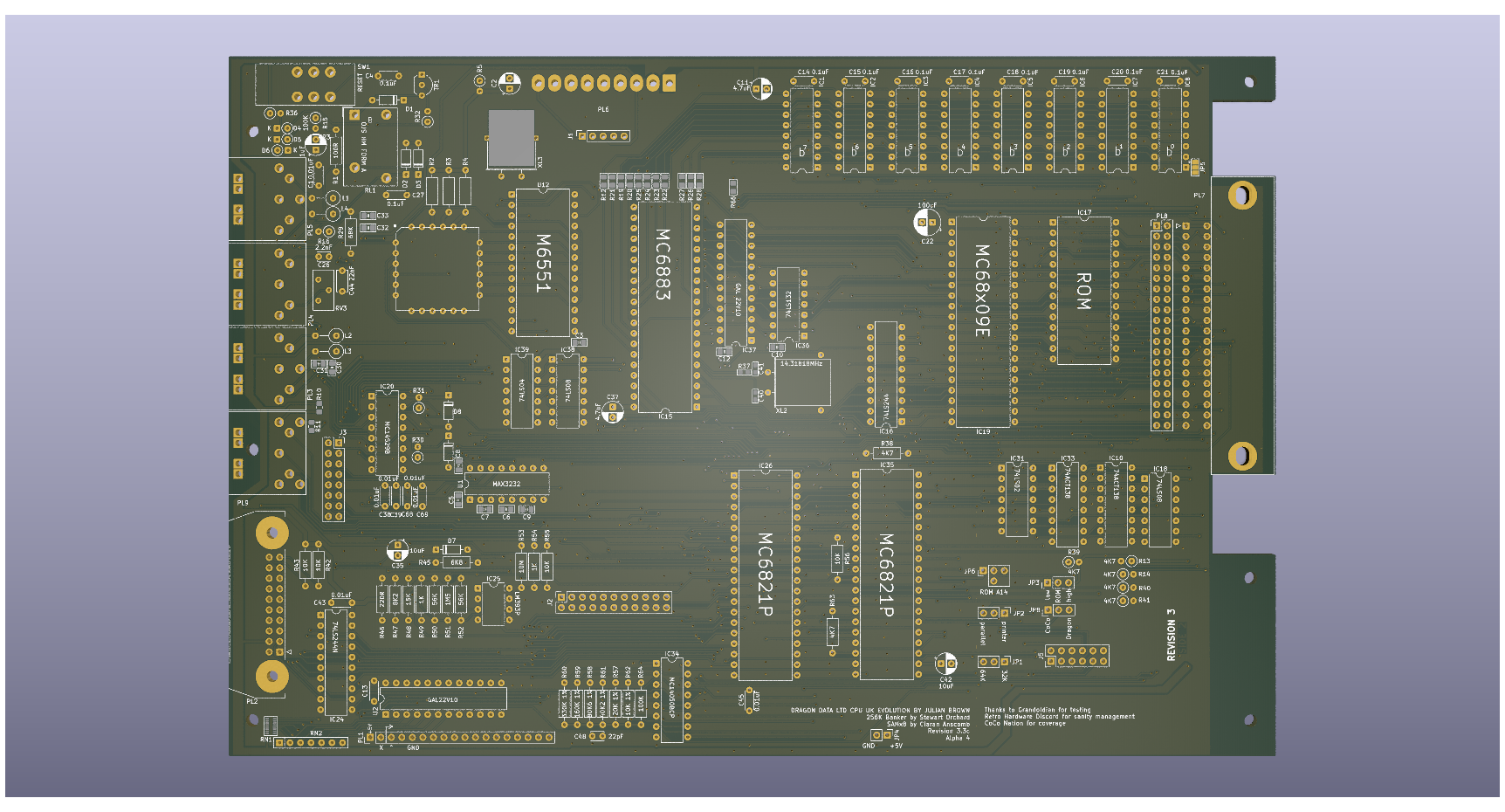
This project started as a recreation of the SA2120 CPU Mainboard for the 1982 Dragon Data Dragon 32
Everything (excluding modifications) is taken from the SA2120 schematics. Where this version changes is that the options to use banks of 16K DRAM is gone, you must use 64K DRAMs, with it goes all the extra circuitry for configuring the memory for different types of chip.
The ROM is now a single 27C256 eprom with an option to switch between two images using JP6 or to allow the rom to be automatically selected from the PIA.
A second ROM selection jumper is available at JP3 to be used when a 27C512 is fitted. This swaps the value to A15 between high and low. When a 27C256 is fitted this must be set low.
Hidden on the back of the board is a solder pad jumper (JP7) that also needs setting to handle a 27C256 or 27C512. Bridging pad 1 sets pin 22 of the rom to ground, using pad 3 sets the pin to use the ROM select signal shared with pin 20. When a 27C512 is fitted this must be set to pad 1.
The video circuits have been isolated from the rest of the board to improve output quality.
A second (internal) cartridge port has been added, by way of a 2x20 header, along with an additional +5V/Gnd pickup point for further internal expansion.
An optional 256K banking solution is incorporated using the design for Stewart Orchard's upgrade board and GAL design. https://gitlab.com/sorchard001/dragon-256k-banker-board
In the current state (3.3) most of the board is tested except for the additional audio capabilities, SAMx8 compatibility and the logic controlled switching of keyboard configuration.
The two joystick ports provide a second fire button capability wired to consecutive keyboard rows, as per the Tandy CoCo. Unless a two button joystick is used this make no difference to the operation of the computer. It also requires the use of 6-pin DIN sockets, these are pin compatible with the 5-pin originals so a regular single button joystick can still be used.
The two extra buttons can also be disabled by omitting L3 and L4.
A jumper (JP2) has been introduced to bypass the logic inverter on the STROBE line. When bypassed the parallel port should operate as a communication port for DRIVEWIRE.
The board is configurable between 32k and 64k ram addressing using jumper JP1. In most scenarios there is no reason to disable the 64k option.
The upgrade to 256K needs the 4164s swapping for 41256s. The pre-bridged jumper at JP5 needs cutting. The SAM also needs to be replaced with a 74LS785. The optional components can then be fitted and should work without further alteration.
The required JED file for the GAL22V10 that drives the memory banking is in the CPLD folder of the project.
The 256K upgrade can be replaced with a SAMx8 upgrade board. This replaces the SAM chip and the tristate buffer that sits between the RAM and the CPU, and also allows connection to the second data path that goes to the VDG. With this in place the DRAM (either 4164 or 41256) is redundant, as is the GAL that provides the 256K banker capability.
The board includes a third connector for the video mezzanine card. This exposes the video board to the CPU side of the data bus along with control signals that would permit programming of the video for additional features. With a stock 6847 that might be to include a programmable character "rom" but I'm also working on a synthetic FPGA based replacement for the 6847 that will allow much bigger changes such as swappable/programmable colour palettes.
The board provides a position to mount a custom implementation of the AY sound generator. This provides three channels of synthesised sound without using the CPU intensive system that the Dragon comes with by default. The capabilities are the same as those of the Spectrum 128 models. You can even mix the old and new methods of sound generation to create more noise!
Theoretically other sound generators could be used but the AY option provides a cheap, capable mechanism that follows a standard familiar to users of other computers from the era.
The board places a GAL chip between the input register of PIA 1 and the keyboard connector. The GAL could be ommitted and jumpers used to hardwire the connections to either Dragon or CoCo compatibility.
With a GAL in place the wiring is controlled by a jumper.
Many of the original components are simply unobtainable or just very hard (and expensive) to locate. The transistors will need modern substitutes as the BC141, BC212 and 2N2369 are all obsolete but thankfully these are fairly run-of-the-mill transistors and shouldn't cause any particular issues.
The CPU and PIAs are all fairly easy to obtain online and possibly even new (MC6821s are still made and there are lots of compatible alternatives). A and B rated components should all be usable but make sure the processor is an "09e". The Hitachi HD6309 is usable but may cause crashes in some software due to lazy coding.
Ciaran Anscomb's samX4 can be used to replace the SAM chip and can be configured to operate as a 74LS783 or a 74LS785 to suit.
As these parts become harder to find it is inevitable that replacements and redesigns will be needed. After much hard work by the Dragon and CoCo community the only IC on the required, that is not still made or in plentiful supply is the MC6847 VDG (the LM1889 on the PAL board is also in limited supply but there are ways around the issue).
The Hitachi HD6309 has been in production until recently due to military supply contracts making it easily accessible and at reasonable cost. Ultimately this will diminish but with supplies still high it seems likely to be available for a long time yet.
The MC6821 is available new but at eye watering prices as it is only made in small batches. The WD65C21 is a direct swap and in much higher supply making it generally cheaper than remaining original NOS parts.
The LS and CD discrete logic chips are all generally easy to obtain and all have more modern equivalents that can be swapped in.
Some searching may be needed for the cartridge port connector. A direct replacement part is listed in the EDAC catalogue but is only made to demand which requires an order of some 200 units. Lower quality but compatible parts can be found online.
Ultimately all of the parts will become hard to obtain but for the foreseeable future the board should remain viable.
| Qty | Value | Footprint | References |
|---|---|---|---|
| 12 | 22R | PCM_Resistor_SMD_AKL:R_0805_2012Metric_Pad1.20x1.40mm_HandSolder | R12, R19, R20, R21, R22, R23, R24, R25, R26, R27, R28, R66 |
| 10 | 0.1uF | Capacitor_THT:C_Disc_D4.3mm_W1.9mm_P5.00mm | C4, C14, C15, C16, C17, C18, C19, C20, C21, C27 |
| 8 | 0.01uF | Capacitor_THT:C_Disc_D4.3mm_W1.9mm_P5.00mm | C1, C13, C38, C39, C43, C45, C68, C69 |
| 8 | 100nF | PCM_Capacitor_SMD_AKL:C_0805_2012Metric_Pad1.18x1.45mm_HandSolder | C3, C5, C6, C7, C8, C9, C10, C12 |
| 8 | 4164 | Package_DIP:DIP-16_W7.62mm | IC1, IC2, IC3, IC4, IC5, IC6, IC7, IC8 |
| 8 | 4K7 | Resistor_THT:R_Axial_DIN0207_L6.3mm_D2.5mm_P2.54mm_Vertical | R13, R14, R30, R31, R32, R39, R40, R41 |
| 6 | 1N914 | Diode_THT:D_DO-35_SOD27_P7.62mm_Horizontal | D1, D2, D3, D7, D8, D9 |
| 5 | 1K | Resistor_THT:R_Axial_DIN0207_L6.3mm_D2.5mm_P10.16mm_Horizontal | R2, R3, R4, R49, R54 |
| 4 | 10K | Resistor_THT:R_Axial_DIN0207_L6.3mm_D2.5mm_P10.16mm_Horizontal | R42, R43, R55, R56 |
| 4 | 22nF | PCM_Capacitor_SMD_AKL:C_0805_2012Metric_Pad1.18x1.45mm_HandSolder | C30, C31, C32, C33 |
| 4 | 3.3uH | Inductor_THT:L_Axial_L7.0mm_D3.3mm_P5.08mm_Vertical_Fastron_MICC | L1, L2, L3, L4 |
| 3 | 10uF | Capacitor_THT:CP_Radial_D5.0mm_P2.50mm | C2, C35, C42 |
| 3 | 1N914 | Diode_THT:D_DO-35_SOD27_P2.54mm_Vertical_KathodeUp | D4, D5, D6 |
| 2 | 100K | Resistor_THT:R_Axial_DIN0207_L6.3mm_D2.5mm_P2.54mm_Vertical | R15, R36 |
| 2 | 4.7uF | Capacitor_THT:CP_Radial_D5.0mm_P2.50mm | C11, C37 |
| 2 | 4K7 | Resistor_THT:R_Axial_DIN0207_L6.3mm_D2.5mm_P10.16mm_Horizontal | R38, R63 |
| 2 | 4K7 | Resistor_SMD:R_0805_2012Metric_Pad1.20x1.40mm_HandSolder | R10, R11 |
| 2 | 56K | Resistor_THT:R_Axial_DIN0207_L6.3mm_D2.5mm_P10.16mm_Horizontal | R50, R52 |
| 2 | 74LS08 | Package_DIP:DIP-14_W7.62mm | IC18, IC38 |
| 2 | 74LS244N | Package_DIP:DIP-20_W7.62mm | IC16, IC24 |
| 2 | MC6821 | Package_DIP:DIP-40_W15.24mm | IC26, IC35 |
| 1 | 1.8432MHz | Crystal:Crystal_HC18-U_Horizontal_1EP_style2 | XL3 |
| 1 | 100K | Resistor_THT:R_Axial_DIN0207_L6.3mm_D2.5mm_P10.16mm_Horizontal | R64 |
| 1 | 100R | Resistor_THT:R_Axial_DIN0207_L6.3mm_D2.5mm_P10.16mm_Horizontal | R1 |
| 1 | 100uF | Capacitor_THT:CP_Radial_D6.3mm_P2.50mm | C22 |
| 1 | 10K 1% | Resistor_THT:R_Axial_DIN0207_L6.3mm_D2.5mm_P10.16mm_Horizontal | R62 |
| 1 | 10M | Resistor_THT:R_Axial_DIN0207_L6.3mm_D2.5mm_P10.16mm_Horizontal | R53 |
| 1 | 14.31818MHz | Crystal:Crystal_HC49-U_Horizontal | XL2 |
| 1 | 15K | Resistor_THT:R_Axial_DIN0207_L6.3mm_D2.5mm_P10.16mm_Horizontal | R48 |
| 1 | 160K 1% | Resistor_THT:R_Axial_DIN0207_L6.3mm_D2.5mm_P10.16mm_Horizontal | R59 |
| 1 | 1K | Resistor_THT:R_Axial_DIN0207_L6.3mm_D2.5mm_P2.54mm_Vertical | R5 |
| 1 | 1K5 | PCM_Resistor_SMD_AKL:R_0603_1608Metric_Pad1.05x0.95mm_HandSolder | R37 |
| 1 | 1M5 | Resistor_THT:R_Axial_DIN0207_L6.3mm_D2.5mm_P10.16mm_Horizontal | R51 |
| 1 | 1uF | Capacitor_THT:CP_Radial_D5.0mm_P2.50mm | C23 |
| 1 | 2.2nF | Capacitor_THT:C_Disc_D3.0mm_W2.0mm_P2.50mm | C26 |
| 1 | 20K 1% | Resistor_THT:R_Axial_DIN0207_L6.3mm_D2.5mm_P10.16mm_Horizontal | R57 |
| 1 | 220R | Resistor_THT:R_Axial_DIN0207_L6.3mm_D2.5mm_P10.16mm_Horizontal | R46 |
| 1 | 22nF | Capacitor_THT:C_Disc_D5.0mm_W2.5mm_P5.00mm | C44 |
| 1 | 22pF | Capacitor_THT:C_Disc_D3.0mm_W2.0mm_P2.50mm | C48 |
| 1 | 22pF | PCM_Capacitor_SMD_AKL:C_0603_1608Metric_Pad1.08x0.95mm_HandSolder | C40 |
| 1 | 27C256 | Package_DIP:DIP-28_W15.24mm | IC17 |
| 1 | 27C512 | Jumper:SolderJumper-3_P1.3mm_Open_Pad1.0x1.5mm | JP7 |
| 1 | 32k/64k | Connector_PinHeader_2.54mm:PinHeader_1x03_P2.54mm_Vertical | JP1 |
| 1 | 330K 1% | Resistor_THT:R_Axial_DIN0207_L6.3mm_D2.5mm_P10.16mm_Horizontal | R60 |
| 1 | 33K | Resistor_THT:R_Axial_DIN0207_L6.3mm_D2.5mm_P2.54mm_Vertical | R16 |
| 1 | 33pF | PCM_Capacitor_SMD_AKL:C_0603_1608Metric_Pad1.08x0.95mm_HandSolder | C41 |
| 1 | 40K2 1% | Resistor_THT:R_Axial_DIN0207_L6.3mm_D2.5mm_P10.16mm_Horizontal | R61 |
| 1 | 470R | Potentiometer_THT:Potentiometer_Bourns_3386X_Horizontal | RV3 |
| 1 | 4K7x6 | Resistor_THT:R_Array_SIP7 | RN2 |
| 1 | 4k7 | PCM_Resistor_SMD_AKL:R_Array_Convex_8x0602 | RN1 |
| 1 | 5vPower | Connector_PinHeader_2.54mm:PinHeader_1x02_P2.54mm_Vertical | JP4 |
| 1 | 68K | Resistor_THT:R_Axial_DIN0207_L6.3mm_D2.5mm_P10.16mm_Horizontal | R29 |
| 1 | 6K8 | Resistor_THT:R_Axial_DIN0207_L6.3mm_D2.5mm_P10.16mm_Horizontal | R45 |
| 1 | 74ACT138 | Package_DIP:DIP-16_W7.62mm | IC10 |
| 1 | 74ACT138N | Package_DIP:DIP-16_W7.62mm | IC33 |
| 1 | 74LS02N | Package_DIP:DIP-14_W7.62mm | IC31 |
| 1 | 74LS04 | Package_DIP:DIP-14_W7.62mm | IC39 |
| 1 | 74LS132 | Package_DIP:DIP-14_W7.62mm | IC36 |
| 1 | 80K6 1% | Resistor_THT:R_Axial_DIN0207_L6.3mm_D2.5mm_P10.16mm_Horizontal | R58 |
| 1 | 8K2 | Resistor_THT:R_Axial_DIN0207_L6.3mm_D2.5mm_P10.16mm_Horizontal | R47 |
| 1 | Board Interconnect Female | Connector_PinSocket_2.54mm:PinSocket_2x11_P2.54mm_Vertical | J2 |
| 1 | Config | Connector_PinHeader_2.54mm:PinHeader_2x06_P2.54mm_Vertical | J5 |
| 1 | Conn_01x09_Male | Connector_Molex:Molex_KK-396_A-41791-0009_1x09_P3.96mm_Vertical | PL6 |
| 1 | Conn_01x18_Pin | Connector_PinHeader_2.54mm:PinHeader_1x18_P2.54mm_Vertical | PL1 |
| 1 | Conn_02x08_Odd_Even | Connector_PinSocket_2.54mm:PinSocket_2x08_P2.54mm_Vertical | J3 |
| 1 | DIN-5 (180) Cassette | Dragon:DIN-5_DELTRON_671-0501_45deg_Horizontal | PL4 |
| 1 | DIN-6 J/S L | Dragon:DIN-6_DELTRON_671-0601_Horizontal | PL5 |
| 1 | DIN-6 J/S R | Dragon:DIN-6_DELTRON_671-0601_Horizontal | PL3 |
| 1 | EDAC 392-040-558-201 | Dragon:Edge_2x20_P2.54mm_OvalMP | PL7 |
| 1 | EDAC 392-040-558-201 | Connector_PinHeader_2.54mm:PinHeader_2x20_P2.54mm_Vertical | PL8 |
| 1 | GAL | Package_DIP:DIP-24_W7.62mm | IC37 |
| 1 | GAL22V10 | Package_DIP:DIP-24_W7.62mm | U2 |
| 1 | KBD_Config | Connector_PinHeader_2.54mm:PinHeader_1x03_P2.54mm_Vertical | JP8 |
| 1 | LM393P | Package_DIP:DIP-8_W7.62mm | IC25 |
| 1 | LOGO | LOGO | G*** |
| 1 | M6551 | Package_DIP:DIP-28_W15.24mm | U12 |
| 1 | MAX3232 | Package_DIP:DIP-16_W7.62mm | U1 |
| 1 | MC14050BCP | Package_DIP:DIP-16_W7.62mm | IC34 |
| 1 | MC14529B | Package_DIP:DIP-16_W7.62mm | IC20 |
| 1 | MC6809E | Package_DIP:DIP-40_W15.24mm | IC19 |
The 158 most common of 171 parts.


DuPAL-PAL-DUmper/DuPAL_Board
This repository contains the KiCad files and the gerber files for the DuPAL boards.

RetroStack/TRS-80-Model-I-G-E1
Hardware Replica of the TRS-80 Model I Revision G

It measures 253 × 169.1 mm and has 2 copper layers, 1.6 mm thick.
171 parts, built around the MAX3232ID, 27C256-17/J, 74ACT138PC and 74LS04PC. The full list of its parts is on this page, with links to each part's symbol and footprint where PCBKit's library has them.
From the jimbro1000/Dragon32Rev3 repository on GitHub, at the commit this page was made from: the board is Dragon32.kicad_pcb and its schematic Dragon32.kicad_sch. PCBKit opens the board in the browser, with nothing to install.
Its repository publishes it under the MIT licence: you may reuse it on that licence's terms (keep the author's notice, and for a copyleft licence share your changes alike).