2 layers407 × 184 mm
TRS-80-Model I Jap50-E1
RetroStack/TRS-80-Model-I-Jap50-E1
Hardware Replica of the TRS-80 Model I Revision HE11E011550
253 parts1MIT

 RetroStack/TRS-80-Model-I-G-E157
Hardware Replica of the TRS-80 Model I Revision G
TRS-80-Model I G E1 is an open-source printed circuit board by RetroStack, from the RetroStack/TRS-80-Model-I-G-E1 repository on GitHub, published under the MIT licence. It is a 2-layer board of 407 × 184 mm with 230 parts on 375 nets, routed with 9,405 tracks and 383 vias.
It is built around the 74LS367PC, 74LS157PC and 74LS32SC, with the 74LS93SC, 74LS04PC and 74LS74PC among its other parts. Its parts include 67 resistors, 58 capacitors, 4 transistors, 3 connectors and 1 crystal.


This project is a faithful reimplementation of the mainboard of the iconic TRS-80 Model 1 (Revision G) computer. My own revision, the E1, is designed to replicate the original system's functionality by using a PCB design 1-to-1 to the original, including components, interfaces, and even traces. The entire project is available under the MIT license.
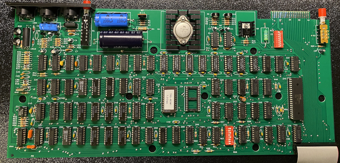
In the "Latest" folder, you'll find the most up-to-date design files, including:
E1 has been implemented using KiCAD 7. The KiCAD project files are included in this repository.
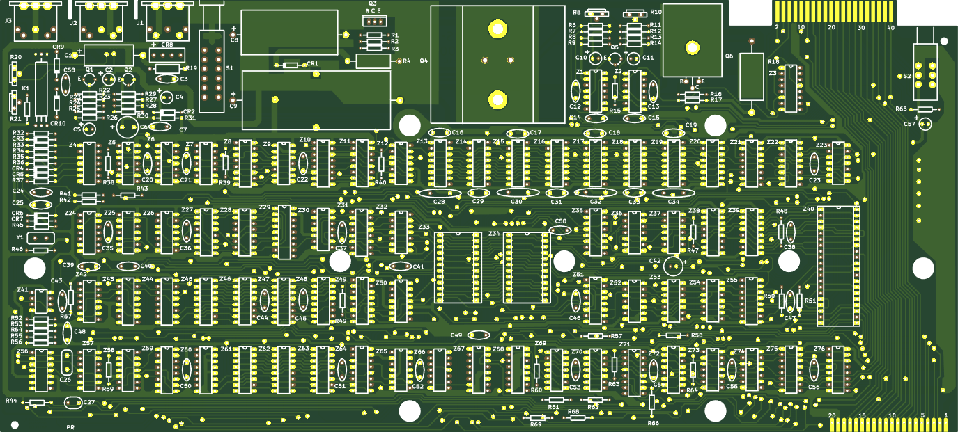
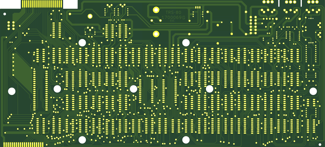
For each step, check if there is a connection between pad 1, 8, 9, 16 on Z18 (all four corners of the dynamic RAM IC). That IC needs all 3 voltages with ground. If any of them are shorted, then you know what you did most recently. Finding the cause of the short should then be relatively easy.
When ordering the board from a PCB manufacturer, you can select the following to get a more faithful version of the board:
Dimension: 407mm x 184mm
Layers: 2
Base Material: FR-4 TG 135-140 (and up)
PCB Thickness: 1.6mm
PCB Color: Green
Silkscreen Color: White
Via Covering: Untented
Surface Finish: Lead Free HASL
Outer Copper Weight: 1oz
Gold Fingers / Card Edge: yes (chamfer: 30 degrees)
Castellated Holes: no
Additionally, supply the following comment for the manufacturer:
Card edge is only on the upper right. The bottom right is just a connector and does not need to be chamfered.
There are some missing pads on the top layer. That is correct. Please leave them as-is.
This addresses recurring questions from some of the interesting designs that were used on the original board which was replicated. See the "Curiosities" page.
Below is a list of materials needed to assemble a complete system. Please note that the links and prices (scroll to the right to see them; as of January 22, 2024) will not be updated in the future and should only be used as a reference for locating the correct items.
Note: Links and alternatives are provided to assist you in finding the necessary components. I cannot guarantee the complete accuracy or reliability of all these links and alternatives. Please check it for yourself!
| Reference | Qty | Description | Source Comment | Source Cost USD | Source Total Cost USD | Source |
|---|---|---|---|---|---|---|
| C1 | 1 | 220uF 16V polarized capacitor | 1.48 | 1.48 | Mouser | |
| C2, C4, C5, C10, C11, C57 | 6 | 10uF 16V polarized capacitor | 0.29 | 1.74 | Mouser | |
| C3, C7, C14, C15 | 4 | 0.01uF 24V (103) capacitor | 0.23 | 0.92 | Mouser | |
| C6 | 1 | 100uF 16V polarized capacitor | 0.37 | 0.37 | Mouser | |
| C8 | 1 | 2200uF 35V polarized capacitor | 5.31 | 5.31 | Mouser | |
| C9 | 1 | 10000uF 16V polarized capacitor | 7.87 | 7.87 | Mouser | |
| C12, C13 | 2 | 470pF (471) capacitor | 0.23 | 0.46 | Mouser | |
| C16, C17, C18, C19, C22, C23, C28, C29, C30, C31, C32, C33, C34, C35, C36, C37, C38, C39, C40, C41, C44, C45, C46, C47, C48, C49, C50, C51, C52, C53, C54, C55, C56, C58 | 34 | 0.1uF 25V (104) capacitor | 0.17 | 5.78 | Mouser | |
| C20 | 1 | 330pF (331) capacitor | 0.3 | 0.3 | Mouser | |
| C21 | 1 | 750pF (750) capacitor | 0.37 | 0.37 | Mouser | |
| C24, C25 | 2 | 220pF (221) capacitor | 0.23 | 0.46 | Mouser | |
| C26 | 1 | 0.047uF (47nF) capacitor | 1.9 | 1.9 | Mouser | |
| C27 | 1 | 0.022uF (22nF) capacitor | 1.34 | 1.34 | Mouser | |
| C42 | 1 | 22uF 16V polarized capacitor | 0.1 | 0.1 | Mouser | |
| C43 | 1 | 47pF (47) capacitor | 0.4 | 0.4 | Mouser | |
| CR1 | 1 | 1N4735 Zener diode | 0.25 | 0.25 | Mouser | |
| CR2 | 1 | 1N5231 Zener diode | 0.15 | 0.15 | Mouser | |
| CR3, CR4, CR5, CR6, CR7 | 5 | 1N4148 | Diode | 0.1 | 0.5 | Mouser |
| CR8 | 1 | MDA202 Diode bridge, +ve/AC/AC/-ve | Replacement | 0.61 | 0.61 | Mouser |
| CR9, CR10 | 2 | 1N982 Schottky diode | Replacement, Lower (39V instead of 75V) | 0.26 | 0.52 | Mouser |
| J1, J2, J3 | 3 | 5-pin DIN connector (5-pin DIN-5 stereo) | For metal connector only. The plastic plugs don't fit in it. | 0.386 | 1.158 | AliExpress |
| J100 | 1 | 01x20 Generic connector, single row, 01x20 | 0.5 | 0.5 | Mouser | |
| K1 | 1 | Relay SPST, Normally Open | Slightly smaller than original | 14.84 | 14.84 | DigiKey |
| Q1 | 1 | 2N3904 0.2A Ic, 40V Vce, Small Signal NPN Transistor, TO-92 | 0.35 | 0.35 | Mouser | |
| Q2, Q5 | 2 | 2N3906 -0.2A Ic, -40V Vce, Small Signal PNP Transistor, TO-92 | 0.28 | 0.56 | Mouser | |
| Q3 | 1 | TIP29A (BCE) NPN transistor | 1.01 | 1.01 | Mouser | |
| Q4 | 1 | 2N6594 (BEC) PNP transistor | Replacement (Other: RS2040, MJ2955G) | 4.73 | 4.73 | Mouser |
| Q6 | 1 | MJE34 (BCE) PNP transistor | Replacement | 0.67 | 0.67 | Mouser |
| - | 1 | Q4 Heatsink | 1.01 | 1.01 | Mouser | |
| - | 1 | Q6 Heatsink | Smaller than original | 0.3 | 0.3 | Mouser |
| R1 | 1 | 68 Resistor 0.25W | 0.1 | 0.1 | Mouser | |
| R2 | 1 | 2.7k Resistor 0.25W | 0.1 | 0.1 | Mouser | |
| R3 | 1 | 750 Resistor 0.25W | 0.1 | 0.1 | Mouser | |
| R4 | 1 | 0.33 Resistor 2W | 0.45 | 0.45 | Mouser | |
| R5, R10 | 2 | 1k Potentiometer | 0.57 | 1.14 | Mouser | |
| R6, R7, R16, R53 | 4 | 1.2k Resistor 0.25W | 0.1 | 0.4 | Mouser | |
| R8 | 1 | 100k Resistor 0.25W | 0.1 | 0.1 | Mouser | |
| R9, R11, R12 | 3 | 3.3k Resistor 0.25W | 0.1 | 0.3 | Mouser | |
| R13 | 1 | 2.2k Resistor 0.25W | 0.1 | 0.1 | Mouser | |
| R14 | 1 | 12k Resistor 0.25W | 0.1 | 0.1 | Mouser | |
| R15 | 1 | 1.5k Resistor 0.25W | 0.1 | 0.1 | Mouser | |
| R17 | 1 | 2k Resistor 0.25W | 0.1 | 0.1 | Mouser | |
| R18 | 1 | 5.6 Resistor 3W | 0.57 | 0.57 | Mouser | |
| R19, C_R67 | 2 | 220 Resistor 0.5W | 0.1 | 0.1 | Mouser | |
| R20, R21 | 2 | 100k Potentiometer | 0.57 | 1.14 | Mouser | |
| R22 | 1 | 75 Resistor 0.25W | 0.1 | 0.1 | Mouser | |
| R23 | 1 | 120 Resistor 0.25W | 0.1 | 0.1 | Mouser | |
| R24 | 1 | 680k Resistor 0.25W | 0.1 | 0.1 | Mouser | |
| R25 | 1 | 1.6M Resistor 0.25W | 0.1 | 0.1 | Mouser | |
| R26, R42 | 2 | 1M Resistor 0.25W | 0.1 | 0.2 | Mouser | |
| R27, R64 | 2 | 330 Resistor 0.25W | 0.1 | 0.2 | Mouser | |
| R28 | 1 | 270 Resistor 0.25W | 0.1 | 0.1 | Mouser | |
| R29 | 1 | 1.8k Resistor 0.25W | 0.1 | 0.1 | Mouser | |
| R30 | 1 | 47 Resistor 0.25W | 0.1 | 0.1 | Mouser | |
| R31 | 1 | 10 Resistor 0.25W | 0.1 | 0.1 | Mouser | |
| R32, R43, R44, R47, R65 | 5 | 10k Resistor 0.25W | 0.1 | 0.5 | Mouser | |
| R33, R36 | 2 | 360k Resistor 0.25W | 0.1 | 0.2 | Mouser | |
| R34, R35, R38, R41, R45 | 5 | 470k Resistor 0.25W | 0.1 | 0.5 | Mouser | |
| R37 | 1 | 560k Resistor 0.25W | 0.1 | 0.1 | Mouser | |
| R39, R40, R48, R49, R50, R51, R57, R58, R59, R60, R61, R62, R63, R66, R67, R68, R69 | 17 | 4.7k Resistor 0.25W | 0.1 | 1.7 | Mouser | |
| R46, R52 | 2 | 910 Resistor 0.25W | 0.1 | 0.2 | Mouser | |
| R54, R55 | 2 | 7.5k Resistor 0.25W | 0.1 | 0.2 | Mouser | |
| R56 | 1 | 220k Resistor 0.25W | 0.1 | 0.1 | Mouser | |
| S1 | 1 | Power 4PST | No Cap | 4.34 | 4.34 | DigiKey |
| S2 | 1 | Reset DPST | Red Cap | 1.815 | 1.815 | AliExpress |
| Y1 | 1 | 10.6445 MHz Two pin crystal | Only 10.6MHz | 0.73 | 0.73 | Mouser |
| Z1, Z2 | 2 | LM723C Linear Regulator (adjustable) | 1.04 | 2.08 | Mouser | |
| Z3, Z71 | 2 | 8-Bit DIP Switch | Replacement | 2.07 | 4.14 | Mouser |
| Z4 | 1 | LM3900 Quad operational amplifier | 0.6 | 0.6 | Mouser | |
| Z5 | 1 | 74C00 quad 2-input NAND gate | 74HC00 works in a pinch, but suboptimal video. | ~2.50 | ~2.50 | eBay/Jameco |
| Z6, Z57 | 2 | 74C04 Hex Inverter | 74HC00 works in a pinch, but suboptimal video. | 2.49 | 4.98 | Jameco |
| Z7, Z69, Z70 | 3 | 74LS74 Dual D Flip-flop, Set & Reset | 0.49 | 1.47 | Mouser | |
| Z8 | 1 | 74LS153 Dual Multiplexer 4 to 1 | 1.13 | 1.13 | Mouser | |
| Z9, Z42, Z52 | 3 | 74LS04 Hex Inverter | 0.67 | 2.01 | Mouser | |
| Z10, Z11 | 2 | 74LS166 Shift Register 8-bit, parallel load | 1.24 | 2.48 | Mouser | |
| Z12, Z32, Z50, Z65 | 4 | 74LS93 Divide by 2 & 8 counter | 3.04 | 12.16 | Mouser | |
| Z13, Z14, Z15, Z16, Z17, Z18, Z19, Z20 | 8 | 4116 16kBit x 1 Bit Dynamic RAM | 3.95 | 31.6 | Jameco | |
| Z21 | 1 | 74LS156 Dual 2 to 4 lines Decoder/Demultiplexer, Open Collector | 0.75 | 0.75 | Mouser | |
| Z22, Z38, Z39, Z44, Z55, Z60, Z67, Z68, Z72, Z75, Z76 | 11 | 74LS367 Hex buffer 3-State outputs | 1.44 | 15.84 | Mouser | |
| Z23, Z25, Z36, Z73 | 4 | 74LS32 Quad 2-input OR | 0.56 | 2.24 | Mouser | |
| Z24, Z53 | 2 | 74LS132 Quad 2-input NAND Schmitt trigger | 1.03 | 2.06 | Mouser | |
| Z26 | 1 | 74LS20 Dual 4-input NAND | 1.28 | 1.28 | Mouser | |
| Z27, Z59 | 2 | 74LS175 4-bit D Flip-Flop, reset | 1.02 | 2.04 | Mouser | |
| Z28 | 1 | 74LS174 Hex D-type Flip-Flop, reset | 1.12 | 1.12 | Mouser | |
| Z29 | 1 | MCM6670 128 x 7 x 5 Character Generator | Adapter needed | 0 | GitHub | |
| Z30, Z37 | 2 | 74LS02 quad 2-input NOR gate | 0.55 | 1.1 | Mouser | |
| Z31, Z35, Z43, Z49, Z51, Z64 | 6 | 74LS157 Quad 2 to 1 line Multiplexer | 0.88 | 5.28 | Mouser | |
| Z33 | 1 | 2364 (20-pin Low) 2364 64kBit (8kb x 8) PROM | Adapter needed | 0 | - | |
| Z34 | 1 | 2332 (20- & 21-pin Low) 2332 32kBit (4kb x 8) PROM | Adapter needed | 0 | - | |
| Z40 | 1 | Z80 CPU | 9.62 | 9.62 | Mouser | |
| Z41 | 1 | 75452 Dual-Peripheral Drivers for High-Current, High-Speed Switching | 0.9 | 0.9 | Mouser | |
| Z45, Z46, Z47, Z48, Z61, Z62, Z63 | 7 | 2102 1K Static RAM (SRAM) | 7th IC needed for lowercase mod | 2.95 | 20.65 | Jameco |
| Z54 | 1 | 74LS30 8-input NAND | 1.18 | 1.18 | Mouser | |
| Z56, Z58 | 2 | 74LS92 Divide by 12 counter | 3.27 | 6.54 | Mouser | |
| Z66 | 1 | 74LS11 Triple 3-input AND | 0.91 | 0.91 | Mouser | |
| Z74 | 1 | 74LS00 quad 2-input NAND gate | 0.57 | 0.57 | Mouser | |
| 1 | DIP-8 Socket | Optional | 0.49 | 0.49 | Jameco | |
| 30 | DIP-14 Socket | Optional | 0.75 | 22.5 | Jameco | |
| 39 | DIP-16 Socket | Optional | 0.85 | 33.15 | Jameco | |
| 1 | DIP-18 Socket | Optional | 0.99 | 0.99 | Jameco | |
| 2 | DIP-24 Socket | Optional | 1.49 | 2.98 | Jameco | |
| 1 | DIP-40 Socket | Optional | 1.69 | 1.69 | Jameco |
To work with this KiCAD project, you'll need the RetroStack libraries for KiCAD. Please follow this link to access and install these libraries.
For additional resources related to the TRS-80 Model 1, be sure to check out the central page for the TRS-80 Model 1 on RetroStack.
RetroStack is passionate about exploring and preserving the legacy of older computer systems. My work involves creating detailed documentation and videos to share the knowledge. I am also dedicated to reviving these classic systems by reimplementing them and offering replacement parts at no cost. If you're keen on supporting this unique project, I invite you to visit my Patreon page. Your support would be immensely valuable and greatly appreciated!
This project is licensed under the MIT License - see the LICENSE file for details.
| Qty | Value | Footprint | References |
|---|---|---|---|
| 31 | 0.1uF 12V | RetroStackLibrary:TRS80_Model_I_C_Disc_9.5L_4W_6P_Small | C16, C17, C18, C19, C22, C23, C29, C31, C33, C35, C36, C37, C38, C39, C40, C41 +15 |
| 17 | 4.7k | RetroStackLibrary:TRS80_Model_I_R_0.25W | R39, R40, R48, R49, R50, R51, R57, R58, R59, R60, R61, R62, R63, R66, R67, R68 +1 |
| 11 | 74LS367 | RetroStackLibrary:TRS80_Model_I_DIP16 | Z22, Z38, Z39, Z44, Z55, Z60, Z67, Z68, Z72, Z75, Z76 |
| 8 | 4116 | RetroStackLibrary:TRS80_Model_I_DIP16 | Z13, Z14, Z15, Z16, Z17, Z18, Z19, Z20 |
| 7 | 2102 | RetroStackLibrary:TRS80_Model_I_DIP16 | Z45, Z46, Z47, Z48, Z61, Z62, Z63 |
| 6 | 10uF 16V | RetroStackLibrary:TRS80_Model_I_C_Pol_Radial_5D_2.5P | C2, C4, C5, C10, C11, C57 |
| 6 | 74LS157 | RetroStackLibrary:TRS80_Model_I_DIP16 | Z31, Z35, Z43, Z49, Z51, Z64 |
| 5 | 10k | RetroStackLibrary:TRS80_Model_I_R_0.25W | R32, R43, R44, R47, R65 |
| 5 | 1N4148 | RetroStackLibrary:TRS80_Model_I_D | CR3, CR4, CR5, CR6, CR7 |
| 5 | 470k | RetroStackLibrary:TRS80_Model_I_R_0.25W | R34, R35, R38, R41, R45 |
| 4 | 0.01uF 24V | RetroStackLibrary:TRS80_Model_I_C_Disc_9.5L_4W_6P_Small | C3, C7, C14, C15 |
| 4 | 0.1uF 25V | RetroStackLibrary:TRS80_Model_I_C_Disc_18.5L_4W_8.5P_Large | C28, C30, C32, C34 |
| 4 | 1.2k | RetroStackLibrary:TRS80_Model_I_R_0.25W | R6, R7, R16, R53 |
| 4 | 74LS32 | RetroStackLibrary:TRS80_Model_I_DIP14 | Z23, Z25, Z36, Z73 |
| 4 | 74LS93 | RetroStackLibrary:TRS80_Model_I_DIP14 | Z12, Z32, Z50, Z65 |
| 3 | 3.3k | RetroStackLibrary:TRS80_Model_I_R_0.25W | R9, R11, R12 |
| 3 | 74LS04 | RetroStackLibrary:TRS80_Model_I_DIP14 | Z9, Z42, Z52 |
| 3 | 74LS74 | RetroStackLibrary:TRS80_Model_I_DIP14 | Z7, Z69, Z70 |
| 3 | Front View | RetroStackLibrary:TRS80_Model_I_DIN5 | J1, J2, J3 |
| 2 | 100k | RetroStackLibrary:TRS80_Model_I_R_Pot | R20, R21 |
| 2 | 1M | RetroStackLibrary:TRS80_Model_I_R_0.25W | R26, R42 |
| 2 | 1N982 | RetroStackLibrary:TRS80_Model_I_D | CR9, CR10 |
| 2 | 1k | RetroStackLibrary:TRS80_Model_I_R_Pot | R5, R10 |
| 2 | 220pF | RetroStackLibrary:TRS80_Model_I_C_Disc_9.5L_4W_6P_Small | C24, C25 |
| 2 | 2N3906 | RetroStackLibrary:TRS80_Model_I_Q_Circle_EBC | Q2, Q5 |
| 2 | 330 | RetroStackLibrary:TRS80_Model_I_R_0.25W | R27, R64 |
| 2 | 360k | RetroStackLibrary:TRS80_Model_I_R_0.25W | R33, R36 |
| 2 | 470pF | RetroStackLibrary:TRS80_Model_I_C_Disc_9.5L_4W_6P_Small | C12, C13 |
| 2 | 7.5k | RetroStackLibrary:TRS80_Model_I_R_0.25W | R54, R55 |
| 2 | 74C04 | RetroStackLibrary:TRS80_Model_I_DIP14 | Z6, Z57 |
| 2 | 74LS02 | RetroStackLibrary:TRS80_Model_I_DIP14 | Z30, Z37 |
| 2 | 74LS132 | RetroStackLibrary:TRS80_Model_I_DIP14 | Z24, Z53 |
| 2 | 74LS166 | RetroStackLibrary:TRS80_Model_I_DIP16 | Z10, Z11 |
| 2 | 74LS175 | RetroStackLibrary:TRS80_Model_I_DIP16 | Z27, Z59 |
| 2 | 74LS92 | RetroStackLibrary:TRS80_Model_I_DIP14 | Z56, Z58 |
| 2 | 910 | RetroStackLibrary:TRS80_Model_I_R_0.25W | R46, R52 |
| 2 | LM723C | RetroStackLibrary:TRS80_Model_I_DIP14 | Z1, Z2 |
| 2 | ~ | RetroStackLibrary:TRS80_Model_I_DIP16 | Z3, Z71 |
| 1 | 0.022uF | RetroStackLibrary:TRS80_Model_I_C_Box_7.5L_5W_4.5P_Small | C27 |
| 1 | 0.047uF | RetroStackLibrary:TRS80_Model_I_C_Box_11L_5W_6P_Large | C26 |
| 1 | 0.33 | RetroStackLibrary:TRS80_Model_I_R_2W | R4 |
| 1 | 1.5k | RetroStackLibrary:TRS80_Model_I_R_0.25W | R15 |
| 1 | 1.6M | RetroStackLibrary:TRS80_Model_I_R_0.25W | R25 |
| 1 | 1.8k | RetroStackLibrary:TRS80_Model_I_R_0.25W | R29 |
| 1 | 10 | RetroStackLibrary:TRS80_Model_I_R_0.25W | R31 |
| 1 | 10.6445 MHz | RetroStackLibrary:TRS80_Model_I_Crystal | Y1 |
| 1 | 10000uF 16V | RetroStackLibrary:TRS80_Model_I_C_Pol_Axial_63L_25W_71P | C9 |
| 1 | 100k | RetroStackLibrary:TRS80_Model_I_R_0.25W | R8 |
| 1 | 100uF 16V | RetroStackLibrary:TRS80_Model_I_C_Pol_Radial_10D_5P | C6 |
| 1 | 120 | RetroStackLibrary:TRS80_Model_I_R_0.25W | R23 |
| 1 | 12k | RetroStackLibrary:TRS80_Model_I_R_0.25W | R14 |
| 1 | 1N4735 | RetroStackLibrary:TRS80_Model_I_D | CR1 |
| 1 | 1N5231 | RetroStackLibrary:TRS80_Model_I_D | CR2 |
| 1 | 2.2k | RetroStackLibrary:TRS80_Model_I_R_0.25W | R13 |
| 1 | 2.7k | RetroStackLibrary:TRS80_Model_I_R_0.25W | R2 |
| 1 | 220 | RetroStackLibrary:TRS80_Model_I_R_0.5W | R19 |
| 1 | 220 | RetroStackLibrary:TRS80_Model_I_R_0.25W | C_R67 |
| 1 | 2200uF 35V | RetroStackLibrary:TRS80_Model_I_C_Pol_Axial_41L_19W_48P | C8 |
| 1 | 220k | RetroStackLibrary:TRS80_Model_I_R_0.25W | R56 |
| 1 | 220uF 16V | RetroStackLibrary:TRS80_Model_I_C_Pol_Axial_21L_9W_29P | C1 |
| 1 | 22uF 16V | RetroStackLibrary:TRS80_Model_I_C_Pol_Radial_6.3D_2.5P | C42 |
| 1 | 2332_20L_21L | RetroStackLibrary:TRS80_Model_I_DIP24 | Z34 |
| 1 | 2364_20L | RetroStackLibrary:TRS80_Model_I_DIP24 | Z33 |
| 1 | 270 | RetroStackLibrary:TRS80_Model_I_R_0.25W | R28 |
| 1 | 2N3904 | RetroStackLibrary:TRS80_Model_I_Q_Circle_EBC | Q1 |
| 1 | 2N6594 | RetroStackLibrary:TRS80_Model_I_Q_Heatsink_Large_BEC | Q4 |
| 1 | 2k | RetroStackLibrary:TRS80_Model_I_R_0.25W | R17 |
| 1 | 330pF | RetroStackLibrary:TRS80_Model_I_C_Disc_9.5L_4W_6P_Small | C20 |
| 1 | 47 | RetroStackLibrary:TRS80_Model_I_R_0.25W | R30 |
| 1 | 47pF | RetroStackLibrary:TRS80_Model_I_C_Disc_9.5L_4W_6P_Small | C43 |
| 1 | 5.6 | RetroStackLibrary:TRS80_Model_I_R_3W | R18 |
| 1 | 560k | RetroStackLibrary:TRS80_Model_I_R_0.25W | R37 |
| 1 | 68 | RetroStackLibrary:TRS80_Model_I_R_0.25W | R1 |
| 1 | 680k | RetroStackLibrary:TRS80_Model_I_R_0.25W | R24 |
| 1 | 74C00 | RetroStackLibrary:TRS80_Model_I_DIP14 | Z5 |
| 1 | 74LS00 | RetroStackLibrary:TRS80_Model_I_DIP14 | Z74 |
| 1 | 74LS11 | RetroStackLibrary:TRS80_Model_I_DIP14 | Z66 |
| 1 | 74LS153 | RetroStackLibrary:TRS80_Model_I_DIP16 | Z8 |
| 1 | 74LS156 | RetroStackLibrary:TRS80_Model_I_DIP16 | Z21 |
| 1 | 74LS174 | RetroStackLibrary:TRS80_Model_I_DIP16 | Z28 |
The 213 most common of 230 parts.
RetroStack/TRS-80-Model-I-Jap50-E1
Hardware Replica of the TRS-80 Model I Revision HE11E011550

clemarfolly/Microdigital-TK2000
Reprodução da PCB do TK-2000 da Microdigital, clone do Micro-Professor MPF-II

RichCini/LomasBoards
Small repository of files/data related to Lomas Data Products S-100 boards.

RetroStack/TRS-80-Model-I-Expansion-Interface-Rev-D
Hardware Replica of the TRS-80 Model I Expansion Interface - Revision D

misterblack1/zenith_zt1
Information gathered on the Zenith ZT-1 / ZT-10 / ZT-11 and ZTX/ZT-x-A variants


It measures 407 × 184 mm and has 2 copper layers, 1.6 mm thick.
230 parts, built around the 74LS367PC, 74LS157PC, 74LS32SC and 74LS93SC. The full list of its parts is on this page, with links to each part's symbol and footprint where PCBKit's library has them.
From the RetroStack/TRS-80-Model-I-G-E1 repository on GitHub, at the commit this page was made from: the board is KiCAD/TRS80_Model_I_G_E1.kicad_pcb and its schematic KiCAD/AddressDecoder.kicad_sch. PCBKit opens the board in the browser, with nothing to install.
Its repository publishes it under the MIT licence: you may reuse it on that licence's terms (keep the author's notice, and for a copyleft licence share your changes alike).