2 layers50 × 30 mm
Pedometer module
InputBlackBoxOutput/INGAME
Virtual reality controller for playing FPS games
52 partsMIT

 InputBlackBoxOutput/INGAME
Virtual reality controller for playing FPS games
Controller module is an open-source printed circuit board by InputBlackBoxOutput, from the InputBlackBoxOutput/INGAME repository on GitHub, published under the MIT licence. It is a 2-layer board of 50 × 35 mm with 73 parts on 58 nets, routed with 929 tracks and 59 vias.
It is built around the ESP32-WROOM-32D, MMC5603NJ and 74HC165D, with the ASM330LHHXTR, DW01A and TP4056 among its other parts. Its parts include 31 resistors, 10 connectors, 8 ICs, 7 capacitors and 5 diodes. It belongs with the ESP32 boards of this library.


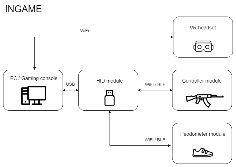
INGAME is a motion emulator with virtual reality features for playing first person shooting/adventure games. Virtual reality (VR) is a simulated experience that can be similar to or completely different from the real world. INGAME has been designed to provide the user with the feeling of being 'IN-the-GAME'. INGAME is modular in nature and consists of the following modules.
The first three modules listed above have been explained in detail later in the document. The VR headset provides split stereo video to the user. The following image shows the functional block diagram of the INGAME system
| Qty | Value | Footprint | References |
|---|---|---|---|
| 19 | 10k | Resistor_SMD:R_0805_2012Metric_Pad1.20x1.40mm_HandSolder | R1, R6, R11, R12, R13, R15, R22, R23, R24, R25, R26, R27, R28, R29, R30, R31 +3 |
| 4 | MountingHole | MountingHole:MountingHole_2.2mm_M2 | H1, H2, H3, H4 |
| 3 | 100R | Resistor_SMD:R_0805_2012Metric_Pad1.20x1.40mm_HandSolder | R5, R10, R18 |
| 3 | 1k | Resistor_SMD:R_0805_2012Metric_Pad1.20x1.40mm_HandSolder | R14, R16, R19 |
| 3 | Conn_01x06_Male | Board:SolderWire_1x06_P2.54mm | J1, J2, J6 |
| 2 | 0.1uF | Capacitor_SMD:C_0603_1608Metric_Pad1.08x0.95mm_HandSolder | C6, C7 |
| 2 | 10k | Resistor_SMD:R_0603_1608Metric_Pad0.98x0.95mm_HandSolder | R20, R21 |
| 2 | 10uF | Capacitor_SMD:C_0805_2012Metric_Pad1.18x1.45mm_HandSolder | C1, C2 |
| 2 | 5k | Resistor_SMD:R_0805_2012Metric_Pad1.20x1.40mm_HandSolder | R3, R4 |
| 2 | 74HC165 | Package_SO:TSSOP-16_4.4x5mm_P0.65mm | U6, U7 |
| 2 | AO3400A | Package_TO_SOT_SMD:SOT-23 | Q1, Q2 |
| 2 | Conn_01x04_Female | Board:SolderWire_1x04_P2.00mm | J8, J9 |
| 2 | SW_Push | Button_Switch_SMD:SW_SPST_B3U-1000P | SW1, SW2 |
| 1 | 0.1uF | Capacitor_SMD:C_0805_2012Metric_Pad1.18x1.45mm_HandSolder | C3 |
| 1 | 1.2k | Resistor_SMD:R_0805_2012Metric_Pad1.20x1.40mm_HandSolder | R17 |
| 1 | 100nF | Capacitor_SMD:C_0603_1608Metric_Pad1.08x0.95mm_HandSolder | C4 |
| 1 | 12k | Resistor_SMD:R_0805_2012Metric_Pad1.20x1.40mm_HandSolder | R2 |
| 1 | 2.2uF | Capacitor_SMD:C_0603_1608Metric_Pad1.08x0.95mm_HandSolder | C5 |
| 1 | AO3401A | Package_TO_SOT_SMD:SOT-23 | Q3 |
| 1 | ASM330LHHXTR | Board:ASM330LHHXTR | U4 |
| 1 | Buzzer | Buzzer_Beeper:Buzzer_Murata_PKMCS0909E4000-R1 | BZ1 |
| 1 | Conn_01x02 | Board:SolderWire_1x02_P2.00mm | J3 |
| 1 | Conn_01x02_Female | Board:SolderWire_1x02_P2.00mm | J5 |
| 1 | Conn_01x05_Female | Board:SolderWire_1x05_P2.00mm | J7 |
| 1 | Conn_01x06_Female | Board:SolderWire_1x06_P2.54mm | J4 |
| 1 | DW01A | Package_TO_SOT_SMD:SOT-23-6_Handsoldering | IC1 |
| 1 | D_Schottky | Diode_SMD:D_SMA | D5 |
| 1 | ESP32-WROOM-32D | Board:ESP32-WROOM-32 | U2 |
| 1 | FS8205A | Board:SOP65P640X120-8N | Q4 |
| 1 | LED | LED_SMD:LED_0805_2012Metric_Pad1.15x1.40mm_HandSolder | D1 |
| 1 | LED-BLUE | LED_SMD:LED_0805_2012Metric_Pad1.15x1.40mm_HandSolder | D4 |
| 1 | LED-RED | LED_SMD:LED_0805_2012Metric_Pad1.15x1.40mm_HandSolder | D3 |
| 1 | LED_RGB | LED_SMD:LED_RGB_5050-6 | D2 |
| 1 | ME6211 | Package_TO_SOT_SMD:SOT-23-5_HandSoldering | U1 |
| 1 | MMC5603NJ | Board:MMC5603NJ | U5 |
| 1 | SW_SPST | Board:SolderWire_1x02_P2.00mm | SW3 |
| 1 | TP4056 | Board:SOP127P600X175-9N | U3 |
| 1 | USB_C_Plug_USB2.0 | Board:GCT_USB4151-GF-C_REVA | P1 |
It measures 50 × 35 mm and has 2 copper layers, 1.6 mm thick.
73 parts, built around the ESP32-WROOM-32D, MMC5603NJ, 74HC165D and ASM330LHHXTR. The full list of its parts is on this page, with links to each part's symbol and footprint where PCBKit's library has them.
From the InputBlackBoxOutput/INGAME repository on GitHub, at the commit this page was made from: the board is modules/Controller module/board/board.kicad_pcb and its schematic modules/Controller module/board/BMS.kicad_sch. PCBKit opens the board in the browser, with nothing to install.
Its repository publishes it under the MIT licence: you may reuse it on that licence's terms (keep the author's notice, and for a copyleft licence share your changes alike).
InputBlackBoxOutput/INGAME
Virtual reality controller for playing FPS games


g210101021/OpenStylophone-RP2040
Overview • Technical Summary • Architecture • Hardware Audit & Remediation • Schematic Subsystems • PCB Layout • Firmware Roadmap • Bill of Materials • Author

GuzziFlipFlops/ESP32-Walkie-Talkie
An open source ESPNOW based walkie talkie with a 600 meter tested distance, with an OLED and multiple buttons to interact with


BrandonFors/convention_pcb_badge
Design for a custom pcb badge for opensauce convention and maybe other conventions in the future.

jonny190/TableLight
A 3D-printable, battery-powered, USB-C rechargeable table lamp in the classic "Poldina" shape - honeycomb disc base, thin stem, down-firing cone shade with a white top - running WLED on an ESP32, with a capacitive touch…

Pedro-Seixas/Smartwatch
A custom-designed smartwatch built around the ESP32-S3, combining BLE connectivity, a rectangular touch display, recharge capability, IMU and temperature sensors. Designed from the ground up in KiCad.


Sumya99/RobotCarPCB
NAND сургалтын төвийн сурагчдад зориулсан робот машины PCB төсөл