2 layers61 × 61 mm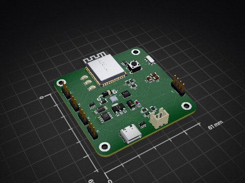

 InputBlackBoxOutput/Bicopter1
Design files for a PCB Bicopter
Bicopter is an open-source printed circuit board by InputBlackBoxOutput, from the InputBlackBoxOutput/Bicopter repository on GitHub, published under the MIT licence. It is a 2-layer board of 150 × 40 mm with 79 parts on 59 nets, routed with 922 tracks and 54 vias.
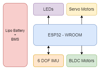
It is built around the ESP32-WROOM-32, MT3608 and DW01A, with the MPU-6050, TP4056 and AO3400A among its other parts. Its parts include 26 resistors, 10 diodes, 9 connectors, 7 capacitors and 7 ICs. It belongs with the ESP32 boards of this library.


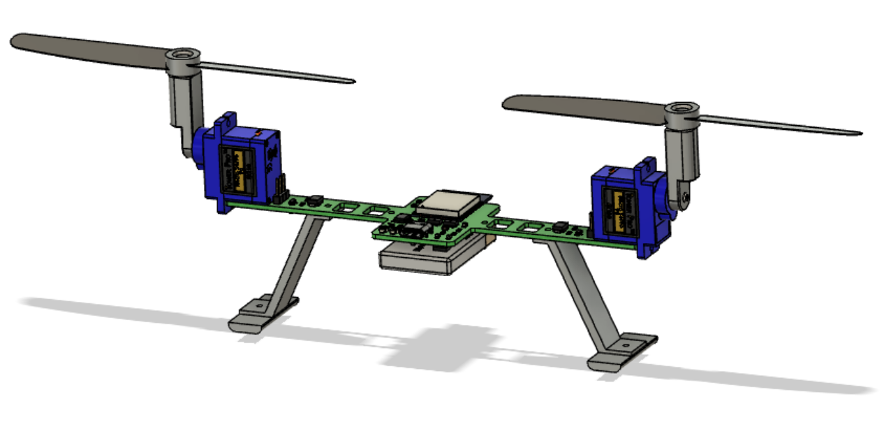
A bicopter is a type of unmanned aerial vehicle that features two rotors for generating lift and controlling its movement. Unlike traditional quadcopters, which have four rotors, bicopters use only two rotors to achieve flight.
| Qty | Value | Footprint | References |
|---|---|---|---|
| 10 | 1k | Resistor_SMD:R_0805_2012Metric_Pad1.20x1.40mm_HandSolder | R3, R4, R5, R13, R14, R16, R22, R23, R25, R26 |
| 9 | 10k | Resistor_SMD:R_0805_2012Metric_Pad1.20x1.40mm_HandSolder | R2, R7, R8, R9, R11, R12, R18, R20, R21 |
| 4 | 100R | Resistor_SMD:R_0805_2012Metric_Pad1.20x1.40mm_HandSolder | R1, R6, R19, R24 |
| 4 | LED | LED_SMD:LED_0805_2012Metric_Pad1.15x1.40mm_HandSolder | D2, D3, D4, D10 |
| 4 | MountingHole | MountingHole:MountingHole_2.2mm_M2 | H1, H2, H3, H4 |
| 2 | 0.1uF | Capacitor_SMD:C_0805_2012Metric_Pad1.18x1.45mm_HandSolder | C3, C7 |
| 2 | 10uF | Capacitor_SMD:C_0805_2012Metric_Pad1.18x1.45mm_HandSolder | C1, C2 |
| 2 | 22uF | Capacitor_SMD:C_0805_2012Metric_Pad1.18x1.45mm_HandSolder | C5, C6 |
| 2 | AO3400A | Package_TO_SOT_SMD:SOT-23 | Q1, Q2 |
| 2 | Conn_01x03_Male | Connector_PinHeader_2.54mm:PinHeader_1x03_P2.54mm_Vertical | J1, J2 |
| 2 | Conn_01x04 | Board:Wire-Pad-01x04 | J6, J8 |
| 2 | Conn_01x06 | Connector_PinHeader_1.00mm:PinHeader_1x06_P1.00mm_Vertical_SMD_Pin1Left | J3, J5 |
| 2 | SS-12 | Diode_SMD:D_SMB | D1, D5 |
| 2 | SW_Push | Button_Switch_SMD:SW_SPST_B3U-1000P | SW1, SW2 |
| 1 | 1.2k | Resistor_SMD:R_0805_2012Metric_Pad1.20x1.40mm_HandSolder | R17 |
| 1 | 2.2nF | Capacitor_SMD:C_0805_2012Metric_Pad1.18x1.45mm_HandSolder | C4 |
| 1 | 22uH | Inductor_SMD:L_10.4x10.4_H4.8 | L1 |
| 1 | 4.7k | Resistor_SMD:R_0805_2012Metric_Pad1.20x1.40mm_HandSolder | R10 |
| 1 | 7.5k | Resistor_SMD:R_0805_2012Metric_Pad1.20x1.40mm_HandSolder | R15 |
| 1 | A+ | Board:Wire-Pad | TP1 |
| 1 | A- | Board:Wire-Pad | TP2 |
| 1 | AO3401A | Package_TO_SOT_SMD:SOT-23 | Q3 |
| 1 | B+ | Board:Wire-Pad | TP3 |
| 1 | B- | Board:Wire-Pad | TP4 |
| 1 | Conn_01x02 | Board:Wire-Pad-01x02 | J7 |
| 1 | Conn_01x06_Female | Board:Wire-Pad-01x06 | J4 |
| 1 | DW01A | Package_TO_SOT_SMD:SOT-23-6_Handsoldering | IC1 |
| 1 | ESP32-WROOM-32 | RF_Module:ESP32-WROOM-32 | U3 |
| 1 | FS8205A | Board:SOP65P640X120-8N | Q4 |
| 1 | HT7833-1-SOT89 | Package_TO_SOT_SMD:SOT-89-3 | U2 |
| 1 | HT7850-1-SOT89 | Package_TO_SOT_SMD:SOT-89-3 | U1 |
| 1 | LED-BLUE | LED_SMD:LED_0805_2012Metric_Pad1.15x1.40mm_HandSolder | D7 |
| 1 | LED-RED | LED_SMD:LED_0805_2012Metric_Pad1.15x1.40mm_HandSolder | D6 |
| 1 | MPU-6050 | Sensor_Motion:InvenSense_QFN-24_4x4mm_P0.5mm | U4 |
| 1 | MT3608 | Package_TO_SOT_SMD:SOT-23-6 | U5 |
| 1 | SS14 | Diode_SMD:D_SMB | D9 |
| 1 | SS34 | Diode_SMD:D_SMC_Handsoldering | D8 |
| 1 | SW_SPST | Board:SW_SPDT_PCM12 | SW3 |
| 1 | TP4056 | Board:SOP127P600X175-9N | U6 |
| 1 | USB_C_Plug_USB2.0 | Connector_USB:USB_C_Receptacle_HRO_TYPE-C-31-M-12 | P1 |
The 75 most common of 79 parts.
It measures 150 × 40 mm and has 2 copper layers, 1.6 mm thick.
79 parts, built around the ESP32-WROOM-32, MT3608, DW01A and MPU-6050. The full list of its parts is on this page, with links to each part's symbol and footprint where PCBKit's library has them.
From the InputBlackBoxOutput/Bicopter repository on GitHub, at the commit this page was made from: the board is hardware/board.kicad_pcb. PCBKit opens the board in the browser, with nothing to install.
Its repository publishes it under the MIT licence: you may reuse it on that licence's terms (keep the author's notice, and for a copyleft licence share your changes alike).

jonny190/TableLight
A 3D-printable, battery-powered, USB-C rechargeable table lamp in the classic "Poldina" shape - honeycomb disc base, thin stem, down-firing cone shade with a white top - running WLED on an ESP32, with a capacitive touch…

dev-campusfab/chessLab
Interactive Chess board that brings visuals to the game and can help the player to learn.

EdgeCoil/wiegand-bridge
ESP32-S3 Wiegand reader bridge for Home Assistant: 4-layer board, BOM and ESPHome firmware.

GuzziFlipFlops/ESP32-Walkie-Talkie
An open source ESPNOW based walkie talkie with a 600 meter tested distance, with an OLED and multiple buttons to interact with

justinlindh/bramble
Privacy-first LoRa mesh networking for ESP32-S3, built with ESP-IDF


MAATHES-THILAK-K/ESP32-S3_FLIGHT_CONTROLLER
A custom-designed flight controller based on the ESP32-S3 module, built for compatibility with the esp-fc firmware and Betaflight-like configuration.