

4 layers30 × 48 mm
Esp32 mpu6000
HeyPCB/esp32-sensors-2
ESP32-S3 boards, one sensor each: KiCad 10, JLCPCB-ready, CERN-OHL-S-2.0
26 partsCERN-OHL-S-2.0

 HeyPCB/whisker
Drop-in controller for Petoi's Nybble robot cat running the stock OpenCat firmware: ATmega328P, PCA9685, MPU-6050, USB-C, 3 A buck, protected battery input. 4-layer KiCad 10 board plus printed cradle.
Whisker is an open-source printed circuit board by HeyPCB, from the HeyPCB/whisker repository on GitHub, published under the CERN-OHL-S-2.0 licence. It is a 4-layer board of 64.6 × 55.2 mm with 118 parts on 116 nets, routed with 1,181 tracks and 118 vias.
It is built around the ATMEGA328P-AU, CH340C and PCA9685PW, with the TPS563201DDCR, AT24C64D-SSHM-T and IRM-H638T/TR2 among its other parts. Its parts include 38 capacitors, 34 resistors, 16 connectors, 11 ICs and 6 diodes. It belongs with the power and robots and motor control boards and the AVR (ATmega, ATtiny) boards of this library.


A drop-in controller for Petoi's Nybble robot cat that runs the stock OpenCat firmware, with USB-C, a 3 A buck and a protected battery input.
Part of HeyPCB's open robot boards. Designed end to end with the HeyPCB method on
KiCad 10 (headless pipeline, Freerouting 2.4.1); every number below is measured on the files in this repository.
Mentions of ./run.sh, docs/rules/, blocks/ or parts/ refer to the heypcb-kicad SDK that produced them.
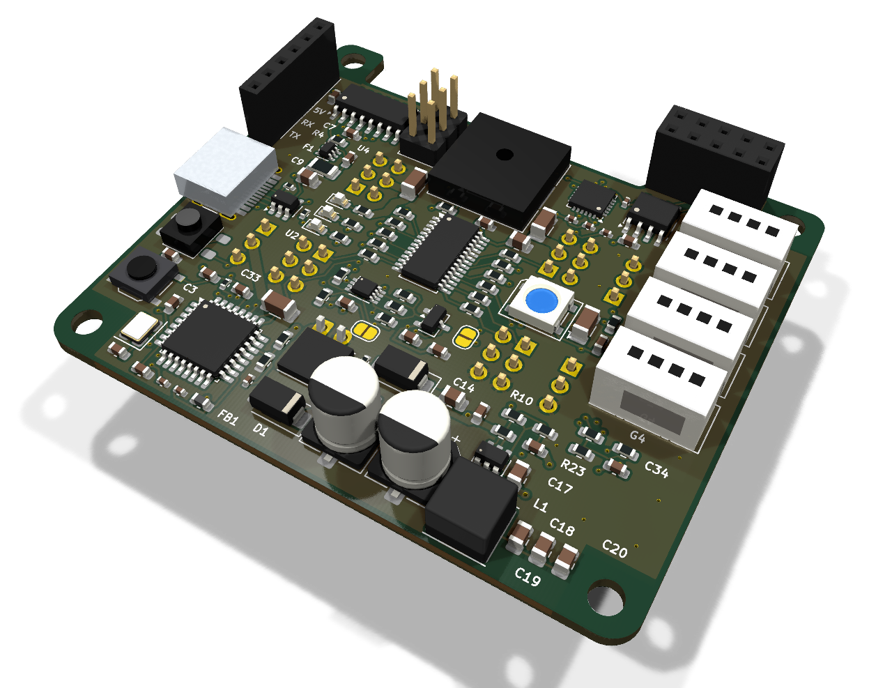
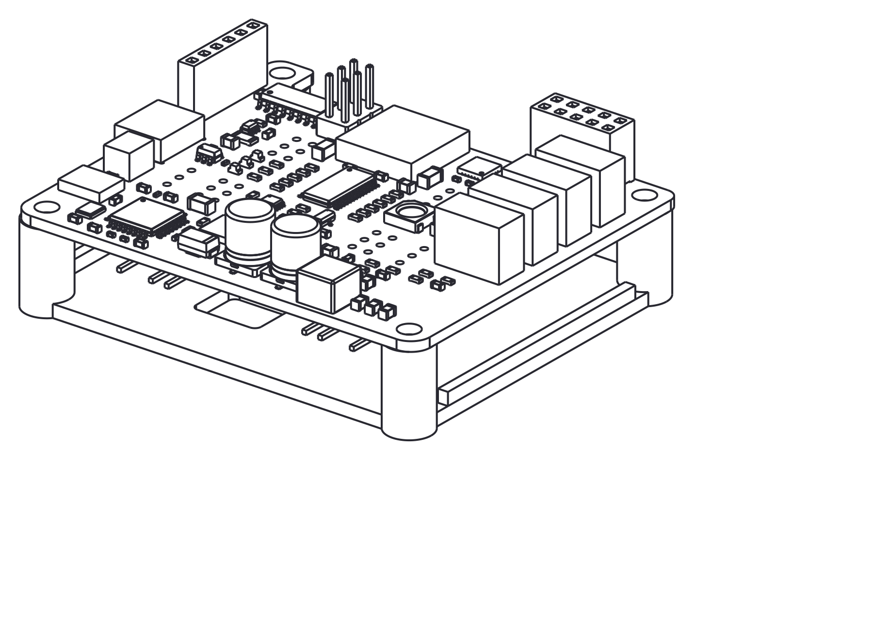
| Layers | Outline | Parts | Nets | Connections routed | Vias | ERC errors | DRC errors / unconnected / parity |
|---|---|---|---|---|---|---|---|
| 4 | 64.8 x 55.4 mm | 118 | 81 | 297 -> 0 open | 118 | 0 | 0 / 0 / 0 |
Not fabricated, assembled or powered.
| KiCad project | kicad/ |
| Gerbers (unzipped and zipped), BOM, CPL, STEP, schematic PDF | fab/ |
| Printed parts (STEP/STL), CadQuery source, fit report | cad/ |
| Renders | top, bottom |
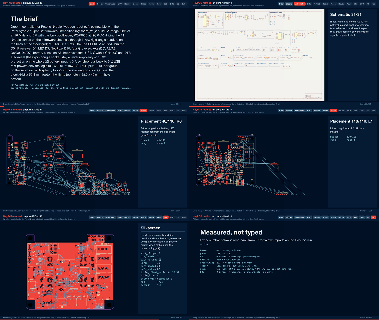
| Design process, every step as KiCad rendered it | media/design-process.mp4 |
Whisker is a controller board for Petoi's Nybble robot cat. It is meant to drop in where the
stock NyBoard V1_2 sits: the same 58.0 x 49.0 mm hole pattern, the same outline with its top
notch, the servo headers at the stock grid on the back. It is compatible with the Petoi Nybble /
OpenCat firmware and needs no firmware change: an ATmega328P at 16 MHz and 5 V with the Uno
bootloader, a PCA9685 at 0x40, an MPU-6050 at 0x68 and a 64 Kbit EEPROM at 0x54, every peripheral
on the MCU pin the NyBoard_V1_2 build expects. Whisker is an independent design. It is not a
Petoi product, and no Petoi schematic, layout or artwork was used.
It was designed with the HeyPCB method on KiCad 10. The headless heypcb-kicad pipeline (KiCad
10.0.6, Freerouting 2.4.1) built it from the brief in board.json. The facts it rests on (pin
map, addresses, servo channels, hole pattern, outline, connector positions) come from the
research spec robots/research/cat/spec.md, which cites the OpenCat sources and the photo and
STL measurements behind each one.
This board has not been fabricated, assembled or powered, and it has not run the firmware.
Firmware compatibility rests on the pin map below, not on a test. Every gate number here is read
from report.json of the final run (2026-10-02). Copper, edge and pour figures were
read from kicad/whisker.kicad_pcb with KiCad's pcbnew. Fit figures are read from
cad/fit.json.
MCU: ATmega328P-AU (TQFP-32) with a 16 MHz crystal, 5 V. AVCC sits behind a ferrite, because AVCC is the reference for the battery reading. There is a reset button at the rear edge and a 2x3 ICSP header for burning the Uno (Optiboot) bootloader once.
Servos: a PCA9685PW at I2C 0x40 (all address pins low, OE low, internal oscillator). It drives the 11 Nybble joints on their firmware channels, each through 1k. The ports are 3-row right-angle headers on the back at the stock grid, with GND toward the board edge. Each header group has 10 uF on the rail.
IMU and storage: an MPU-6050 at 0x68, turned 180 degrees like the stock part, with INT on D2. An AT24C64D EEPROM at 0x54 holds the skills.
I2C: a PCA9306 joins the 5 V MCU bus to the 3.3 V bus (the PCA9685, MPU-6050, EEPROM, Grove G1 and the Pi header). There are 2.2k pull-ups on each side for the firmware's 500 kHz clock. A solder jumper, PI I2C, lets the MCU release the bus to a Raspberry Pi.
USB-C: a CH340C behind a USBLC6-2SC6, with DTR auto-reset through 100 nF. The CH340C's TXD reaches RX through 1k, so a dongle can still drive RX.
6-pin socket: kept for the BT and WiFi dongles, in the Pro Mini order (DTR, TX, RX, 5V, NC, GND), with its own DTR auto-reset. It is a vertical 1x6 socket; the stock one lies flat (see Departures).
Battery input: a keyed JST XH socket on the back for the 2S pack. An AON6411 P-FET blocks a reversed pack for the whole board, servo rail included. An SMAJ10A clamps the protected rail. The servo rail VBAT has 2 x 330 uF low-ESR electrolytics and 4 x 10 uF ceramics.
5 V: a TPS563201 synchronous buck (3 A) fed from VBAT through an SS34, with a 4.7 uH inductor and an 82k / 15k divider: 0.768 V x (1 + 82/15) = 4.97 V. TI's 5 V table (SLVSD90B Table 7-2) gives 54.9k / 10k; 82k and 15k are both pinned Basic parts.
USB power: USB reaches the 5 V rail only, through a 500 mA PTC and an LM66100 ideal diode (CE on its own output). If the buck's body diode back-feeds its input from USB, the SS34 stops it, so USB never powers the servos.
3.3 V: an XC6206 LDO off 5 V.
Peripherals:
Grove: four HY2.0 (Grove-compatible) sockets on the front edge:
Raspberry Pi: a 2x5 socket where a face-to-face Pi's pins 1-10 land.
Board: 4 layers, 64.6 x 55.2 mm, 1.6 mm thick in the gerber job. The stackup is:
There is no plane while routing; see Departures from the spec.
The MCU pins, read back from the run's netlist (design.json). Firmware sources are listed in the spec, section 1.4.
| ATmega328P pin | Arduino | Net | Function (OpenCat NyBoard_V1_2) |
|---|---|---|---|
| 30 / 31 | D0 / D1 | RXD / TXD | serial, 115200 Bd: CH340C (RX through 1k), the 6-pin socket, the Pi (RX through 1k, TX through a divider) |
| 32 | D2 | IMU_INT | MPU-6050 INT (wired; the firmware leaves it unused) |
| 1 | D3 | LED_D3 | green status LED (LED_PIN 3) |
| 2 | D4 | IR | IR receiver (IR_PIN 4) |
| 9 | D5 | BUZZER | piezo (BUZZER 5, tone()) |
| 10 / 11 | D6 / D7 | D6 / D7 | Grove G4 |
| 12 / 13 | D8 / D9 | D8 / D9 | Grove G3 |
| 14 | D10 | NEOPIXEL | WS2812B data, through 330 ohm |
| 15 / 16 / 17 | D11 / D12 / D13 | MOSI / MISO / SCK | ICSP |
| 25 / 26 | A2 / A3 | A2 / A3 | Grove G2. A3 also reaches PCA9685 channel 3 through the open CAL jumper (PWM_READ_PIN A3) |
| 27 / 28 | A4 / A5 | SDA5 / SCL5 | I2C, through the PCA9306 to the 3.3 V bus |
| 22 | A7 | VBAT_SENSE | battery divider, 1:2 (VOLTAGE_DETECTION_PIN A7, LOW_VOLTAGE 650) |
| 29 | RESET | RESET | 10k pull-up, reset button, ICSP; DTR of the CH340C and of the 6-pin socket, and the Pi's GPIO4, each through 100 nF |
| 23, 24, 19 | A0, A1, A6 | none | unused by the V1 firmware, left open |
| I2C device | Address | How it is set |
|---|---|---|
| PCA9685 | 0x40 (All-Call 0x70 also answers) | A0-A5 grounded |
| MPU-6050 | 0x68 | AD0 grounded |
| AT24C64D | 0x54 | A2 high, A1 and A0 low. Petoi's block diagram says 0x51; the text, the V1_2 silkscreen and the firmware say 0x54, and the spec resolves the conflict that way |
Servo ports. The channel map is OpenCat's pwm_pin[] for NyBoard V1_x (spec 1.6).
| Joint | Name | PCA9685 ch | Group | Column x | Header | Silk (back) |
|---|---|---|---|---|---|---|
| 0 | head pan | 12 | upper front | 48.52 | J16 | PAN |
| 1 | head tilt | 11 | lower front | 48.52 | J14 | TILT |
| 2 | tail | 4 | lower rear | 11.26 | J10 | TAIL |
| 8 | left front shoulder | 14 | upper front | 43.44 | J15 | LF SHLD KNEE |
| 12 | left front knee | 15 | upper front | 40.90 | J15 | (same) |
| 9 | right front shoulder | 9 | lower front | 43.44 | J13 | RF SHLD KNEE |
| 13 | right front knee | 8 | lower front | 40.90 | J13 | (same) |
| 10 | right hind hip | 6 | lower rear | 16.34 | J11 | RH |
| 14 | right hind knee | 7 | lower rear | 18.88 | J11 | (same) |
| 11 | left hind hip | 1 | upper rear | 16.34 | J12 | LH |
| 15 | left hind knee | 0 | upper rear | 18.88 | J12 | (same) |
Channels 2, 3, 5, 10 and 13 are unused on Nybble, and their positions are left empty. Channel 3 can feed A3 for the firmware's oscillator calibration once the CAL jumper is bridged.
| Spec or request | On the board | Why |
|---|---|---|
| DMP3013SFV reverse-polarity FET | AON6411 (C81007), -20 V, DFN-8 at 1.27 mm pitch | The PowerDI3333 land puts the gate pad 0.65 mm from a source pad. A 1.0 mm servo-rail track cannot reach source pins 2 and 3 at 0.2 mm clearance; Freerouting runs without neck-down. |
| Passive buzzer on a 2N7002 (stock), MLT-8530 suggested | PKLCS1212E4001 12 x 12 mm piezo, driven from D5 through 100 ohm | KiCad 10 has no land for the MLT-8530 (spec 6). A piezo is a capacitive load and needs no driver or flyback diode. It is 3 mm tall. |
| WS2812C-2020 on KiCad's WS2812B-2020 symbol, "check the pin-out" (spec 6) | WS2812B 5050 (WS2812B-B/T, C2761795) | The repository's rules bind a part only to the symbol for its own package. The 5050 is the part KiCad's LED:WS2812B symbol and land are drawn for (pins 1 VDD, 2 DOUT, 3 VSS, 4 DIN), so no pin-out needs checking. |
| I2C master slide switch, kept (spec 4, item 13) | PI I2C solder jumper | The master is chosen once per build, so copper does it, with no part to source or place on the crowded front. Open (the default) keeps the MCU as master. Bridged, it grounds the PCA9306's EN, so a Pi on the 2x5 drives the bus alone. |
| Pi GPIO4 to RST (spec 1.2; no circuit given) | GPIO4 through 100 nF to RESET | A falling edge resets the MCU, as DTR does. A static level, high or low, does nothing. |
| 1x6 female socket lying flat, opening toward +y (stock, spec 1.7) | vertical 1x6 socket (C40877) on KiCad's PinSocket_1x06_P2.54mm_Vertical land, within 0.3 mm of the photo's pin positions | Not matched. A dongle plugged in stands up from the board instead of lying along it; see Check before ordering. |
| 3-row x 4 right-angle headers | per group, one 2-column and one 1-column land (or one 2-column): KiCad's straight 2x3 / 1x3 lands, on the back, holding a 3-row right-angle header snapped from a 3x3 (PZ254-3-03-W-2.5-G0) | KiCad 10 has no 3-row right-angle land. Separate 1x3 lands at 2.54 mm overlap courtyards. Omitting the five unused channels leaves a pair plus a single per group. |
| Grove sockets at 10.4 mm pitch, plus a 2.54 mm break-out column | sockets at 7.0 mm pitch with their pins along x; no break-out column | At the stock pitch, KiCad's Grove land's 11.4 mm courtyard overlaps its neighbour. The freed lower-right corner holds the Pi's level-shift parts. An 8 mm pitch was tried, and its route left a GND pin open. |
| Notch at least x 6.5-45.1 (spec 2.7) | notch x 6.4-44.8, floor at y 49.6 | The Pi socket sits at the Pi's own pin positions. Its pads keep the 0.5 mm copper-to-edge clearance only with the notch's right edge at 44.8, 0.1 mm inside the photo's 44.9. |
| In1 as the GND plane (the pipeline's default) | no plane while routing; In1 poured 5 V, In2 VBAT, B.Cu GND afterwards | Freerouting mirrors a back-side part's layers. The servo headers' through-hole pins then reach the router with an In1 shape, and Freerouting never joined same-net pin pairs on them (26 and 30 open). With no plane, 297 connections routed to 0. See docs/rules/pipeline.md. |
report.json)| Gate | Result |
|---|---|
| Composition | 31 block instances of 20 blocks (18 new whisker_* blocks and HeyPCB's gpio_led and led_indicator) give 118 parts, 81 nets and 5 explicit no-connects |
Part binding (parts/lcsc_pinned.json) | 112 of 118 parts bound, 0 unsourced, 0 identity conflicts. Two solder jumpers and four holes have nothing to buy. 54 distinct part numbers: 27 Basic, 27 Extended (about $81 in JLC loading fees) |
ERC (kicad-cli sch erc --severity-all) | 0 errors, 0 warnings |
| Netlist round trip | identical, 81 nets |
| Placement | 118 parts, every one locked by the brief. No same-face courtyard overlap and no through-hole inside a courtyard (checked on the placed board before routing) |
| Routing | 297 → 0 open on rung 2. Rung 1 left 3 open with fanout and 12 without. Rung 2 narrowed the PWR5 class (5V, VBUS, VBUS_F) to 0.2 mm, and its last-mile router closed the battery pin to FET drain hop and one GND link, both kept by DRC. 1181 tracks, 109 routing vias, 2676.6 mm of track: F.Cu 835.9, In1 874.1, In2 834.7, B.Cu 132.0 |
| Pours (only after a measured 0 open) | GND on F.Cu and B.Cu, 5V on In1, VBAT on In2. 10 stitching vias (119 vias in all). 0 open after the pour, after stitching and at the end |
| Silkscreen | 11 words, 7 pin labels and 4 title lines placed. 1 stitching via displaced, 20 designators seated and 87 hidden |
DRC (--severity-all --schematic-parity, KiCad 10.0.6) | fresh, 0 errors, 0 unconnected, 0 parity, 4 warnings |
DFM (jlcpcb_4layer) | 0 errors, 1 warning: 422 stock-footprint silk strokes at 0.12 mm, which the fab prints at its 0.15 mm minimum |
| Fab gate | ready, no blockers. Four copper gerbers, gerber job LayerNumber 4. The JLC CPL corrected 9 rotations |
| Media | 63 3D frames, the raytraced renders and the design-process video (1920 x 1080, 179.2 s, 5375 frames by ffprobe) |
The 4 DRC warnings:
lib_footprint_mismatch on J9 (the Pi socket) and J2 (USB-C): the board's copies differ from KiCad's library footprints. These are the two footprints at the board edge, where the silk stage clips footprint silk (7 items clipped in this run).silk_over_copper: JP1's outline arc touches the back battery socket's pin-2 pad.silk_over_copper: the WS2812B footprint's "1" touches C37's rail pad.Read from the final .kicad_pcb with pcbnew. Current figures use heypcb-kicad's route.ipc2221_amps at a 10 C rise. The vias are rated as a 25 um barrel, the way the Spinner README rates its own.
Battery feed (BAT_RAW, pack to FET drain): 6.5 mm on F.Cu, 1.5-2.0 mm wide, no via. The FET's drain pad sits 0.7 mm below the battery pin, so the hop is about 2 mm long.
currentA 5, so the ladder may not narrow it.Servo rail (VBAT): 1.0 mm tracks with three 0.8 / 0.4 mm vias:
5 V: 0.2 mm tracks (the class narrowed by the ladder), 11 vias:
Buck: VBUCK and the switch node are 0.6 mm (about 1.65 A on 1 oz outer copper per track), each with two vias.
Ground: B.Cu is one 2584.3 mm² island of GND around 132 mm of track. The F.Cu GND pour is 1975.9 mm² in 7 islands.
Edges: the nearest bodies to the outline are:
Every other body is at least 0.95 mm inside the photo-measured outline, which is uncertain by +-0.5 mm.
cad/mount.py)A tray that clamps Whisker to Nybble's y1 rails and guards the parts on its back.
mount.py reads the board's real STEP (fab/whisker.step, by reference designator), its footprints through pcbnew, and the frame facts of the spec (sections 2.3-2.6 and 5).Fit, measured with OpenCascade's BRepExtrema_DistShapeShape (cad/fit.json):
| Pair | Minimum | Note |
|---|---|---|
| Cradle to every body below the board (11 parts) | 1.22 mm (J9's pin tails), 1.50 mm (J8's) | the servo header envelopes are 2.48 mm above the floor; no interference |
| Cradle to the mated servo plugs | 2.48 mm | plugs above the floor; they leave past the board's long edges |
| Cradle to the battery plug | 1.50 mm | around the floor opening |
| Cradle to the board body | 0 (contact) | only at the four boss seats (136 mm²); common volume 0.0 mm³ |
| Rails (rebuilt) to the board's top-side bodies (105 parts) | 0.10 mm (J9), 0.20 mm (C20), 0.68 mm (Y1), 0.93 mm (L1) | each is 3.6-10.2 mm from a hole centre, outside the 7 mm seat; the near ones meet the rebuilt boss, not the seat |
| Rails to the cradle | 1.51 mm | the board lies between them |
| Cradle to the belly (rebuilt) | 4.39 mm | lowest board part 8.87 mm, battery plug housing 4.81 mm |
What these numbers rest on:
Rebuilt, not measured, robot frame. The spec's STL measurements give:
The STLs carry no licence and are not used here. The boss outline is this script's guess: a 7 mm disc plus a bridge to the rail, cut at X = 22.5. The belly gap rests on the spec's shared-frame assumption.
Envelopes for parts with no STEP model:
fit.json lists every assumption.
Previews (CadQuery SVG, converted with rsvg-convert), all in cad/:
cradle_iso.png and cradle_top.png;board_on_cradle_iso.png and board_on_cradle_under.png;fit_iso.png (with the rails), fit_side.png and fit_end.png.The board passes ERC, the netlist round trip, routing, DRC (errors, unconnected and parity), DFM and the fab gate in KiCad. None of it has been built.
Fit in the robot
The outline is photo-measured: +-0.5 mm on edges, +-0.3 mm on spacings, from a NyBoard V1_1 photo scaled by its header pitch (spec 2.1-2.2).
The y1 bosses. The Pi socket (0.10 mm) and C20 (0.20 mm) are the closest bodies to the rebuilt rail bosses, whose outline is a guess. Look at the real y1 bosses next to those two parts before ordering.
The dongle socket stands upright. The stock 1x6 socket lies flat with its opening toward the notch, so a plugged dongle rises about 10 mm (spec 2.4). On Whisker the socket is vertical, so a dongle stands up by its own length. Check that it clears the robot's cover, or change J8 to a right-angle socket before ordering.
USB-C access at the tail edge has not been checked against the frame (spec 8). The shell stands 0.6 mm proud of the rear edge.
Heights on top:
The spec estimates the stock board's tallest top part at 6-7 mm. A Pi stacked on the 2x5 sits over the bulk capacitors; that clearance was not checked.
The space under the board (about 16.9 mm from the board to the rebuilt belly) is an estimate from the STLs' shared frame (spec 8, item 2). The cradle leaves 4.39 mm of it.
Firmware-visible choices
v, tilt nose-down and left-side-down) and turn U9 to match if it differs.Current
Parts and assembly
fab/whisker_bom.csv comes from parts/lcsc_pinned.json: 29 rows were looked up live on 2026-10-02 and the rest are older pinned rows (2026-06-23 to 2026-09-30).board.json: the brief the pipeline built everything from.cad/mount.py: the cradle, its fit check and previews. It runs with a Python that has CadQuery and trimesh: python cad/source/mount.py.build/ is regenerated):
report.json;kicad/whisker.kicad_{sch,pcb,pro};fab/: the gerber zip, BOM (55 rows), JLC CPL, positions, schematic PDF and STEP;build/whisker/render/0200_3d.png (top) and 0201_3d.png (bottom), plus the turntable frames;media/design-process.mp4;cad/: the cradle STEP and STL, the board-on-cradle STEP, fit.json and the previews.From the heypcb-kicad repository:
./run.sh --board boards/whisker --no-media   # every gate, 320 s of stages in the final run (routing 287 s)
./run.sh --board boards/whisker              # plus the 3D renders (230 s) and the video (31 s)
python cad/source/mount.py   # a Python with CadQuery and trimesh
Every part is locked by the brief, so placement is identical every run. The final brief routed
the same way twice on 2026-10-02 (--no-media, then the full run): 1181 tracks, 109 vias and
2676.6 mm both times.
Hardware: CERN-OHL-S v2. Files under cad/ that derive from third-party CAD carry their own notice there.
| Qty | Value | Footprint | References |
|---|---|---|---|
| 16 | 1k | Resistor_SMD:R_0603_1608Metric | R4, R19, R20, R21, R22, R24, R25, R26, R27, R28, R29, R30, R31, R32, R33, R34 |
| 12 | 100nF | Capacitor_SMD:C_0603_1608Metric | C3, C6, C7, C8, C16, C17, C23, C24, C31, C32, C33, C34 |
| 6 | 100nF | Capacitor_SMD:C_0402_1005Metric | C4, C5, C13, C26, C28, C30 |
| 5 | 22uF | Capacitor_SMD:C_0805_2012Metric | C14, C15, C18, C19, C20 |
| 4 | 10uF | Capacitor_SMD:C_1206_3216Metric | C35, C36, C37, C38 |
| 4 | 2.2k | Resistor_SMD:R_0603_1608Metric | R13, R14, R15, R16 |
| 4 | GROVE | Connector:NS-Tech_Grove_1x04_P2mm_Vertical | J4, J5, J6, J7 |
| 4 | M3 | MountingHole:MountingHole_3.2mm_M3_ISO14580 | H1, H2, H3, H4 |
| 4 | SERVO x2 (3-row R/A) | Connector_PinHeader_2.54mm:PinHeader_2x03_P2.54mm_Vertical | J11, J12, J13, J15 |
| 3 | 1uF | Capacitor_SMD:C_0603_1608Metric | C10, C21, C22 |
| 3 | SERVO (3-row R/A) | Connector_PinHeader_2.54mm:PinHeader_1x03_P2.54mm_Vertical | J10, J14, J16 |
| 2 | 10k | Resistor_SMD:R_0402_1005Metric | R1, R5 |
| 2 | 10uF | Capacitor_SMD:C_0805_2012Metric | C9, C25 |
| 2 | 12pF | Capacitor_SMD:C_0603_1608Metric | C1, C2 |
| 2 | 20k | Resistor_SMD:R_0603_1608Metric | R7, R8 |
| 2 | 330uF 25V | Capacitor_SMD:CP_Elec_6.3x7.7 | C11, C12 |
| 2 | 5.1k | Resistor_SMD:R_0402_1005Metric | R2, R3 |
| 1 | 100 | Resistor_SMD:R_0603_1608Metric | R17 |
| 1 | 100k | Resistor_SMD:R_0603_1608Metric | R11 |
| 1 | 10nF | Capacitor_SMD:C_0402_1005Metric | C27 |
| 1 | 120R@100MHz | Inductor_SMD:L_0603_1608Metric | FB1 |
| 1 | 15k | Resistor_SMD:R_0603_1608Metric | R10 |
| 1 | 16MHz | Crystal:Crystal_SMD_3225-4Pin_3.2x2.5mm | Y1 |
| 1 | 2.2nF | Capacitor_SMD:C_0603_1608Metric | C29 |
| 1 | 200k | Resistor_SMD:R_0603_1608Metric | R12 |
| 1 | 2k | Resistor_SMD:R_0603_1608Metric | R23 |
| 1 | 330 | Resistor_SMD:R_0603_1608Metric | R18 |
| 1 | 4.7k | Resistor_SMD:R_0603_1608Metric | R6 |
| 1 | 4.7uH | Inductor_SMD:L_Sunlord_SWPA6045S | L1 |
| 1 | 500mA | Fuse:Fuse_1206_3216Metric | F1 |
| 1 | 82k | Resistor_SMD:R_0603_1608Metric | R9 |
| 1 | AON6411 | Package_DFN_QFN:AO_DFN-8-1EP_5.55x5.2mm_P1.27mm_EP4.12x4.6mm | Q1 |
| 1 | AT24C64D | Package_SO:SOIC-8_3.9x4.9mm_P1.27mm | U10 |
| 1 | ATmega328P-AU | Package_QFP:TQFP-32_7x7mm_P0.8mm | U1 |
| 1 | BATT 2S | Connector_JST:JST_XH_B2B-XH-A_1x02_P2.50mm_Vertical | J3 |
| 1 | Blue (5V) | LED_SMD:LED_0603_1608Metric | D6 |
| 1 | CAL | Jumper:SolderJumper-2_P1.3mm_Open_RoundedPad1.0x1.5mm | JP2 |
| 1 | CH340C | Package_SO:SOIC-16_3.9x9.9mm_P1.27mm | U3 |
| 1 | Green (D3) | LED_SMD:LED_0603_1608Metric | D5 |
| 1 | ICSP | Connector_PinHeader_2.54mm:PinHeader_2x03_P2.54mm_Vertical | J1 |
| 1 | IRM-H638T | OptoDevice:Everlight_IRM-H6xxT | U11 |
| 1 | LM66100 | Package_TO_SOT_SMD:SOT-363_SC-70-6 | U4 |
| 1 | MPU-6050 | Sensor_Motion:InvenSense_QFN-24_4x4mm_P0.5mm | U9 |
| 1 | Orange (BAT) | LED_SMD:LED_0603_1608Metric | D3 |
| 1 | PCA9306 | Package_SO:VSSOP-8_2.3x2mm_P0.5mm | U7 |
| 1 | PCA9685PW | Package_SO:TSSOP-28_4.4x9.7mm_P0.65mm | U8 |
| 1 | PI I2C | Jumper:SolderJumper-2_P1.3mm_Open_RoundedPad1.0x1.5mm | JP1 |
| 1 | PKLCS1212E4001 | Buzzer_Beeper:Buzzer_Murata_PKLCS1212E | BZ1 |
| 1 | RESET | Button_Switch_SMD:SW_Push_1P1T_XKB_TS-1187A | SW1 |
| 1 | RPI 1-10 | Connector_PinSocket_2.54mm:PinSocket_2x05_P2.54mm_Vertical | J9 |
| 1 | SERIAL | Connector_PinSocket_2.54mm:PinSocket_1x06_P2.54mm_Vertical | J8 |
| 1 | SMAJ10A | Diode_SMD:D_SMA | D1 |
| 1 | SS34 | Diode_SMD:D_SMA | D2 |
| 1 | TPS563201 | Package_TO_SOT_SMD:SOT-23-6 | U5 |
| 1 | USB-C | Connector_USB:USB_C_Receptacle_HRO_TYPE-C-31-M-12 | J2 |
| 1 | USBLC6-2SC6 | Package_TO_SOT_SMD:SOT-23-6 | U2 |
| 1 | WS2812B | LED_SMD:LED_WS2812B_PLCC4_5.0x5.0mm_P3.2mm | D4 |
| 1 | XC6206P332MR | Package_TO_SOT_SMD:SOT-23-3 | U6 |
It measures 64.6 × 55.2 mm and has 4 copper layers, 1.6 mm thick.
118 parts, built around the ATMEGA328P-AU, CH340C, PCA9685PW and TPS563201DDCR. The full list of its parts is on this page, with links to each part's symbol and footprint where PCBKit's library has them.
From the HeyPCB/whisker repository on GitHub, at the commit this page was made from: the board is kicad/whisker.kicad_pcb and its schematic kicad/whisker.kicad_sch. PCBKit opens the board in the browser, with nothing to install.
Its repository publishes it under the CERN-OHL-S-2.0 licence: you may reuse it on that licence's terms (keep the author's notice, and for a copyleft licence share your changes alike).
HeyPCB/esp32-sensors-2
ESP32-S3 boards, one sensor each: KiCad 10, JLCPCB-ready, CERN-OHL-S-2.0

superfansizhe-beep/tscircuit-stm32f302-board
STM32F302R8T6 考核板 —— 用 tscircuit 以 TypeScript 描述原理图与 PCB,9 页分页、4 层板、含完整交付物


barkinvar/sugerCANe
A compact interface for three NPN, PNP or logic sensors on an FRC robot. Each port has a removable 5 V / 12 V power jumper; input type is configured in software.

kim-xps12/m5stack_board_unitree_brushless_digital_servo
Unitree Servo UART Board for M5Stack: auto-direction 4 Mbps half-duplex TTL bus for Unitree J288 / S288 brushless digital servos (KiCad 9, JLCPCB PCBA)

HeyPCB/iris-cortex
Iris Cortex: head controller of the Iris robot head. ESP32-S3 (16 MB flash, 8 MB PSRAM), OV2640 eye-camera FPC, iris-ring LED drivers, harness hub.
