


6 layers40 × 40 mm
Kestrel fc
HeyPCB/kestrel-fc
Kestrel H7: STM32H743 FPV flight controller with ICM-20602 + BMI088, MS5611, 16 MB blackbox, 5 V and switchable 10 V BECs.
114 partsCERN-OHL-S-2.0

 HeyPCB/kestrel-esc
Kestrel 4in1: 6S 4-in-1 ESC running stock AM32 on four STM32G071s, with 24 CSD18540 FETs, LM5109B drivers and battery current sensing. 48 x 52 mm 6-layer KiCad 10 board, DRC clean, with gerbers, BOM, CPL and STEP.
Kestrel esc is an open-source printed circuit board by HeyPCB, from the HeyPCB/kestrel-esc repository on GitHub, published under the CERN-OHL-S-2.0 licence. It is a 6-layer board of 48 × 52 mm with 174 parts on 151 nets, routed with 1,830 tracks and 238 vias.
It is built around the STM32G071G8U6N, LM5109BSD and INA180A2IDBVR(LX), with the LMR51430YFDDC, L78L33ABUTR-CN and CL05B104KB54PNC among its other parts. Its parts include 52 capacitors, 50 resistors, 24 transistors, 19 ICs and 1 diode. It belongs with the robots and motor control boards and the STM32 boards of this library.


Four STM32G071s running stock AM32, twelve half-bridge drivers and twenty-four 60 V FETs stacked through a 48 x 52 mm board, with battery current sensing for the flight controller.
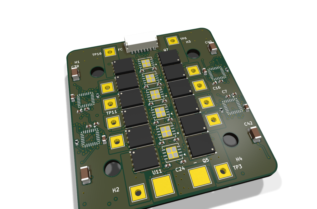
The Kestrel 4in1 is the ESC of Kestrel. Each motor has its own STM32G071 wired to AM32's HARDWARE_GROUP_G0_H pin map, the group of the Mamba F55 G071 build, so it runs a stock AM32 release: firmware/am32/README.md maps every pin and walks through the first flash. Each half bridge is stacked through the board, the high-side FET on the top face over its low side on the bottom, joined by the motor wire soldered through a plated hole.
| Layers | Size | Footprints (LCSC parts) | Nets | Connections routed | Routed vias | ERC errors / warnings | DRC errors / warnings / unconnected / parity | Parts per board, 10-board build |
|---|---|---|---|---|---|---|---|---|
| 6 | 48 x 52 mm | 174 (148) | 119 | 443 -> 0 open | 215 | 0 / 4 | 0 / 0 / 0 / 0 | $44.70 |
Not fabricated, assembled, powered or flown yet. Every number on this page is measured by KiCad
10.0.6 on the files in this repository (report.json, fab/erc.json,
fab/drc.json) or read from the live JLC/LCSC catalogue (bom_cost.md:
parts only, at a 10-board build's price tier with JLC's Extended-part fee; the bare PCB and assembly are
quoted at order time).
The 4 ERC warnings are KiCad's pin-type check on a pin the design ties to a rail on purpose: AM32's per-motor current input, tied to GND: the board measures battery current once, for the FC.
| The whole drone: spec, build guide, BOM, measured results | HeyPCB/kestrel |
| KiCad 10 project | kicad/ |
| Gerbers, drill, BOM, CPL, STEP, schematic PDF | fab/ |
| Firmware | firmware/am32/README.md: stock AM32 (MAMBA_F55_G071), the pin map and the first flash |
| Renders | front, back, hero, Circuit World thumbnail |
| Brief and generator | design/ |
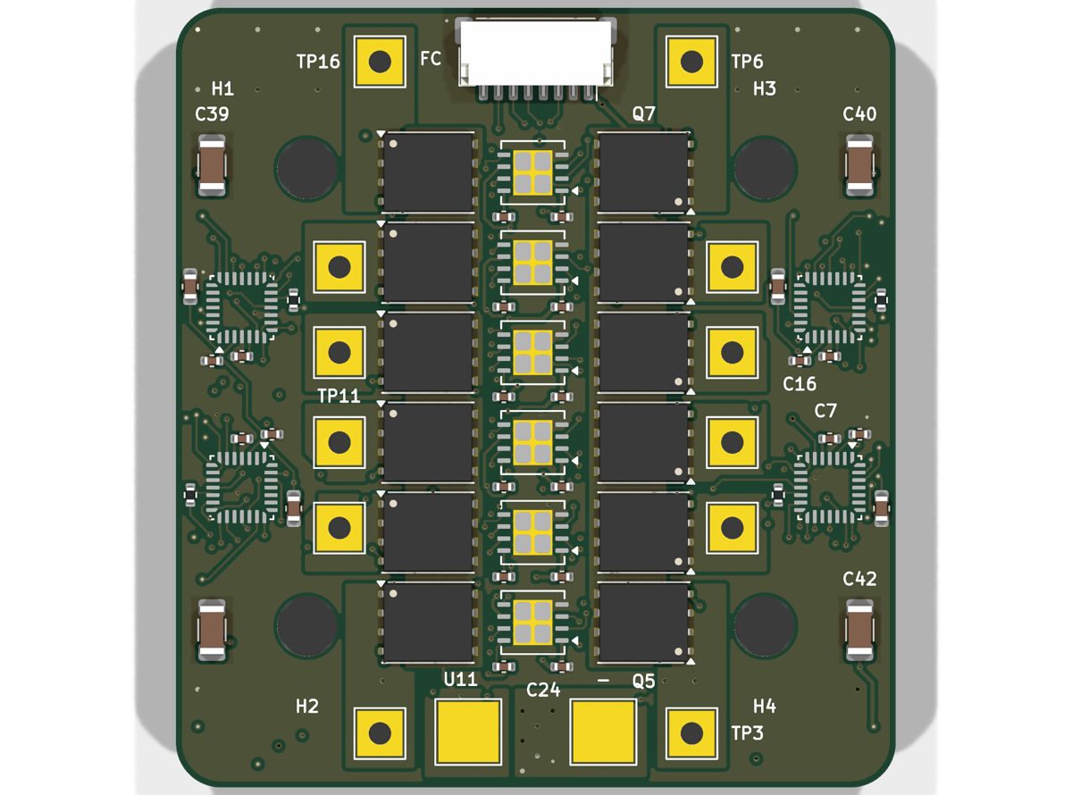
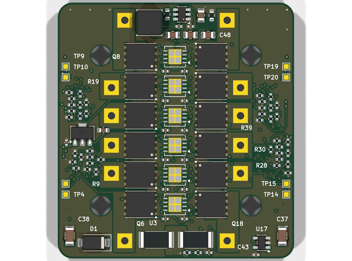
HARDWARE_GROUP_G0_H (the MAMBA_F55_G071 build).ibata_scale 125).6 layers, 1.6 mm, 2 oz outer copper recommended; parts on both faces. Upload fab/kestrel_esc_gerbers.zip, fab/kestrel_esc_bom.csv
and fab/kestrel_esc_cpl_jlc.csv to JLCPCB: every part has an LCSC number.
Bring-up, one board at a time, is in the hub's BUILD.md.
Designed with the HeyPCB method on KiCad 10.0.6, headless, by the heypcb-kicad pipeline: a written brief composed from reusable circuit blocks, every pin from KiCad's own symbol library, every part bound to an LCSC number from a dated catalogue read, then ERC, a netlist round trip, locked placement, Freerouting 2.4.1, pours and stitching, silkscreen, DRC with schematic parity, DFM and a fab gate, each stage gated by a measurement. design/make_brief.py regenerates the brief (outline, part locks, net
classes) from code.
Part of Kestrel, a 5-inch 6S FPV quad's electronics.
Hardware: CERN-OHL-S v2. KiCad's symbol, footprint and 3D libraries used in the design are CC-BY-SA 4.0 with the KiCad library exception.
| Qty | Value | Footprint | References |
|---|---|---|---|
| 24 | 100nF | Capacitor_SMD:C_0402_1005Metric | C2, C11, C13, C15, C16, C18, C20, C22, C24, C25, C27, C29, C31, C33, C34, C36 +8 |
| 24 | 20k | Resistor_SMD:R_0402_1005Metric | R2, R3, R10, R13, R14, R15, R19, R20, R21, R24, R25, R26, R30, R31, R32, R35 +8 |
| 24 | CSD18540Q5B | Package_TO_SOT_SMD:TDSON-8-1 | Q1, Q2, Q10, Q11, Q12, Q13, Q14, Q15, Q16, Q17, Q18, Q19, Q20, Q21, Q22, Q23 +8 |
| 13 | 1uF | Capacitor_SMD:C_0402_1005Metric | C1, C3, C5, C10, C12, C14, C19, C21, C23, C28, C30, C32, C52 |
| 12 | 2.2k | Resistor_SMD:R_0402_1005Metric | R5, R6, R7, R16, R17, R18, R27, R28, R29, R38, R39, R40 |
| 12 | LM5109B | Package_SON:WSON-8-1EP_4x4mm_P0.8mm_EP2.6x3mm | U1, U2, U3, U5, U6, U7, U9, U10, U11, U13, U14, U15 |
| 12 | motor | TestPoint:TestPoint_THTPad_3.0x3.0mm_Drill1.5mm | TP1, TP2, TP3, TP6, TP7, TP8, TP11, TP12, TP13, TP16, TP17, TP18 |
| 6 | 10uF | Capacitor_SMD:C_1206_3216Metric | C37, C38, C39, C40, C41, C42 |
| 4 | 100 | Resistor_SMD:R_0402_1005Metric | R1, R12, R23, R34 |
| 4 | 10uF | Capacitor_SMD:C_0805_2012Metric | C45, C48, C49, C50 |
| 4 | 4.7uF | Capacitor_SMD:C_0603_1608Metric | C8, C17, C26, C35 |
| 4 | 750 | Resistor_SMD:R_0402_1005Metric | R11, R22, R33, R44 |
| 4 | M3 grommet | MountingHole:MountingHole_4mm | H1, H2, H3, H4 |
| 4 | STM32G071G8U6N | Package_DFN_QFN:QFN-28_4x4mm_P0.5mm | U4, U8, U12, U16 |
| 4 | SWCLK | TestPoint:TestPoint_Pad_1.0x1.0mm | TP5, TP10, TP15, TP20 |
| 4 | SWDIO | TestPoint:TestPoint_Pad_1.0x1.0mm | TP4, TP9, TP14, TP19 |
| 2 | 0.5m | Resistor_SMD:R_2512_6332Metric | R45, R46 |
| 1 | 100k | Resistor_SMD:R_0603_1608Metric | R49 |
| 1 | 10k | Resistor_SMD:R_0402_1005Metric | R47 |
| 1 | 1k | Resistor_SMD:R_0402_1005Metric | R48 |
| 1 | 1uF | Capacitor_SMD:C_0603_1608Metric | C51 |
| 1 | 6.49k | Resistor_SMD:R_0603_1608Metric | R50 |
| 1 | 6.8uH | Inductor_SMD:L_Sunlord_SWPA5040S | L1 |
| 1 | BAT+ | TestPoint:TestPoint_Pad_4.0x4.0mm | TP21 |
| 1 | BAT- | TestPoint:TestPoint_Pad_4.0x4.0mm | TP22 |
| 1 | ESC | Connector_JST:JST_SH_SM08B-SRSS-TB_1x08-1MP_P1.00mm_Horizontal | J1 |
| 1 | INA180A2 | Package_TO_SOT_SMD:SOT-23-5 | U17 |
| 1 | L78L33 | Package_TO_SOT_SMD:SOT-89-3 | U19 |
| 1 | LMR51430YF | Package_TO_SOT_SMD:SOT-23-6 | U18 |
| 1 | SMAJ30A | Diode_SMD:D_SMA | D1 |
HeyPCB/kestrel-fc
Kestrel H7: STM32H743 FPV flight controller with ICM-20602 + BMI088, MS5611, 16 MB blackbox, 5 V and switchable 10 V BECs.

kaminaris/GigaESC-Power200V
Compact 50 × 20 mm non-isolated power-supply module for the modular GigaESC platform, intended for the 200 V version. Provides 12 V, 5 V and 3.3 V rails through a separate output connector.

azmat-bilal/bldc_motor_controller_pcb
A Brushless DC Motor controller board. The design is inspired and is compatible with Odrive project (https://github.com/madcowswe/ODriveHardware) except that this one has a single channel.


MAC-75/STM32-Synchronous-Buck-Converter
Design, simulation and optimization-assisted digital control of a 12 V to 5 V synchronous buck converter using MATLAB/Simulink, STM32 and KiCad.

polesskiy-dev/iot-risk-data-logger-nfc-samd21-hardware
Hardware (schematics, PCB, BOM) for iot-risk-data-logger-nfc-samd21 project


ldcyes/OpenDuck
已完成可编辑原理图、真实四层 PCB 和本地库。阶梯板面积 4510 mm²,比原 65×60 + 32×30 mm 两板总面积 4860 mm² 少 350 mm²(7.20%)。原 TDK 模块本体、四个安装孔和原 TDK 器件位置保留,回生电容采用原料号卧装,J1 因实际拔插通道冲突改为同系列 BM08 顶插。当前为工程候选,未制造,未完成热、回生瞬态、低电量或行走验收。
It measures 48 × 52 mm and has 6 copper layers, 1.6 mm thick.
174 parts, built around the STM32G071G8U6N, LM5109BSD, INA180A2IDBVR(LX) and LMR51430YFDDC. The full list of its parts is on this page, with links to each part's symbol and footprint where PCBKit's library has them.
From the HeyPCB/kestrel-esc repository on GitHub, at the commit this page was made from: the board is kicad/kestrel_esc.kicad_pcb and its schematic kicad/kestrel_esc.kicad_sch. PCBKit opens the board in the browser, with nothing to install.
Its repository publishes it under the CERN-OHL-S-2.0 licence: you may reuse it on that licence's terms (keep the author's notice, and for a copyleft licence share your changes alike).