STM32 Buck Converter is an open-source printed circuit board by MAC-75, from the MAC-75/STM32-Synchronous-Buck-Converter repository on GitHub, published under the MIT licence. It is a 2-layer board of 100 × 70 mm with 31 parts on 18 nets, routed with 121 tracks and 26 vias.
It is built around the STM32G431RBT6, LM5109BSD and TPS7A1633DGN, with the CSD18540Q5B, BAS316 and SMBJ18A among its other parts. Its parts include 9 capacitors, 4 resistors, 4 ICs, 3 connectors and 2 diodes. It belongs with the power boards and the STM32 boards of this library.
MATLAB and Simulink models of a 12 V to 5 V synchronous buck converter.
The project includes averaged and PWM switching power-stage models, a
digital PI-controlled averaged model, and a reproducible load-transient
test. The digital-control target is an STM32G431RB.
Project status: This is a design-only project validated with MATLAB,
Simulink, and automated error-level KiCad ERC/DRC checks. No physical
converter prototype has been built or hardware-tested. All waveforms, plots,
and performance values in this repository are simulation results, not bench
measurements.
Design values
Parameter
Value
Input
10 to 14 V
Nominal input
12 V
Output
5 V
Maximum current
2 A
Switching frequency
100 kHz
Inductor
47 µH
Output capacitor
100 µF
Output-capacitor ESR
20 mΩ
Nominal duty cycle
41.67%
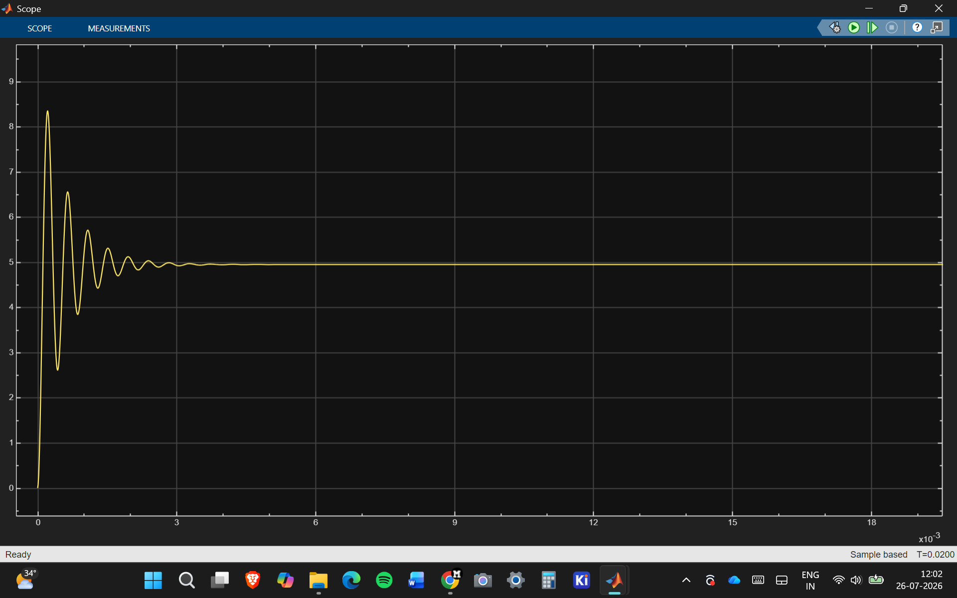
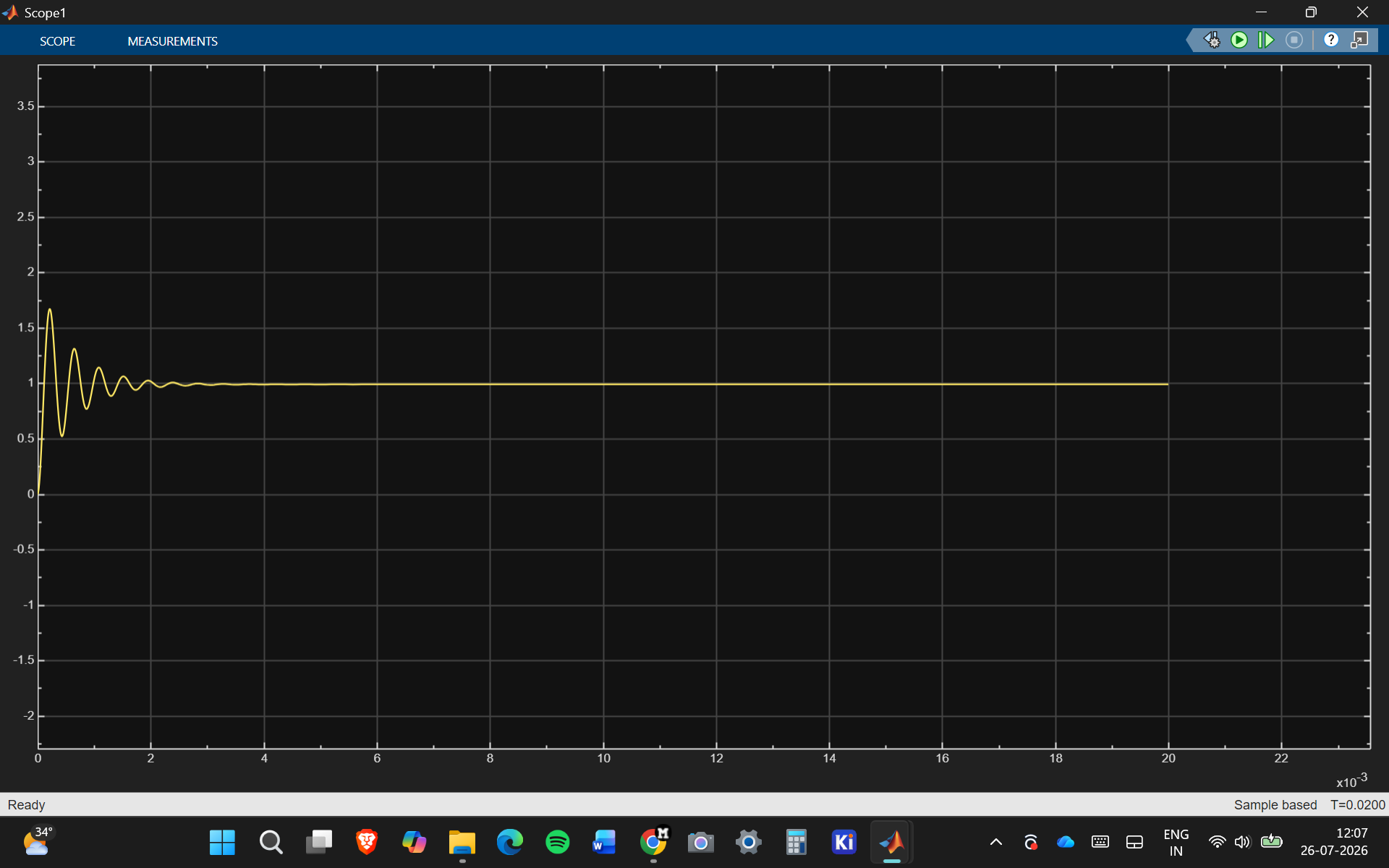
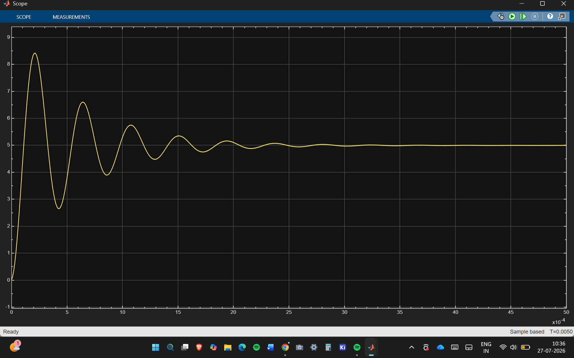
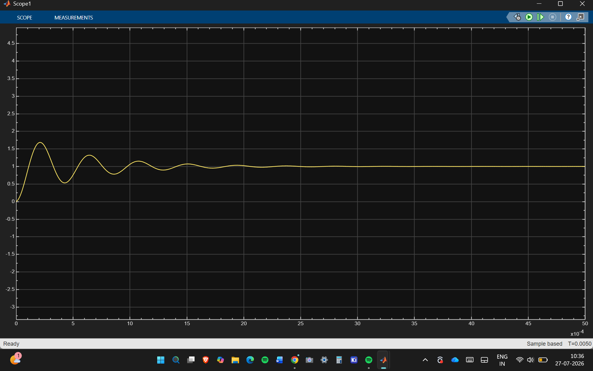
At 12 V input with a 5 Ω load, the open-loop models settle close to
5 V and 1 A. The startup ringing is from the LC output filter.
Simulation results
Averaged model
PWM switching model
Three closed-loop switching cases were checked independently from the
averaged model. Their steady-state inductor-current ranges are 0.5970-1.4357 A
at 12 V/5 ohm, 1.7332-2.2652 A at 10 V/2.5 ohm, and 1.4900-2.5089 A at
14 V/2.5 ohm. The 2.5089 A value is the simulated worst-case peak. Exported
waveforms are restricted to the common time support of every source signal;
the validation rejects nonfinite data, extrapolation, or current magnitude
of 10 A or more.
Closed-loop load transient
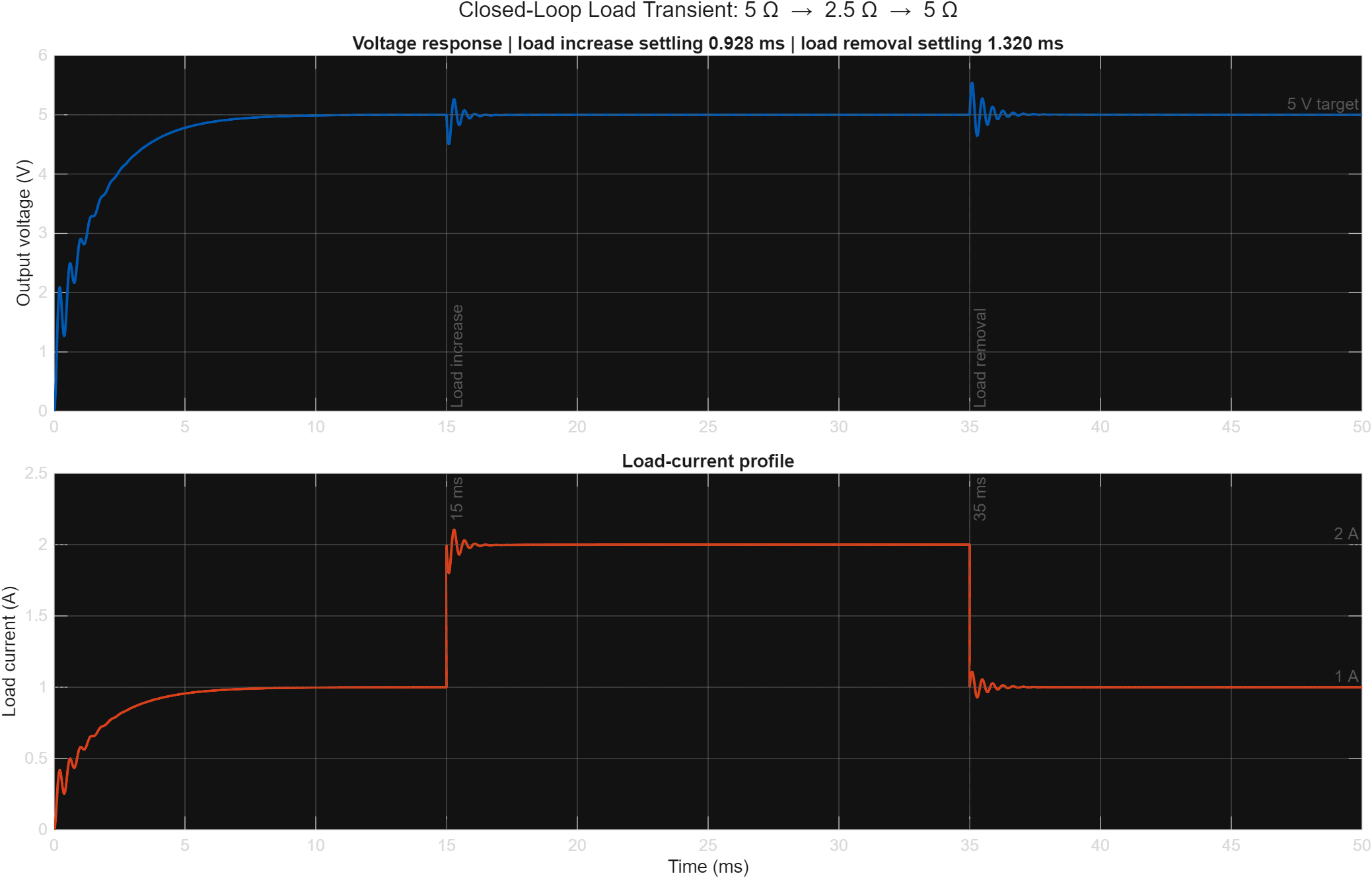
The averaged closed-loop model commands 5 Ω from 0–15 ms, 2.5 Ω from
15–35 ms, and 5 Ω from 35–50 ms. The settled operating points are
approximately 5 V/1 A, 5 V/2 A, and 5 V/1 A. Maximum load current is
2.105 A.
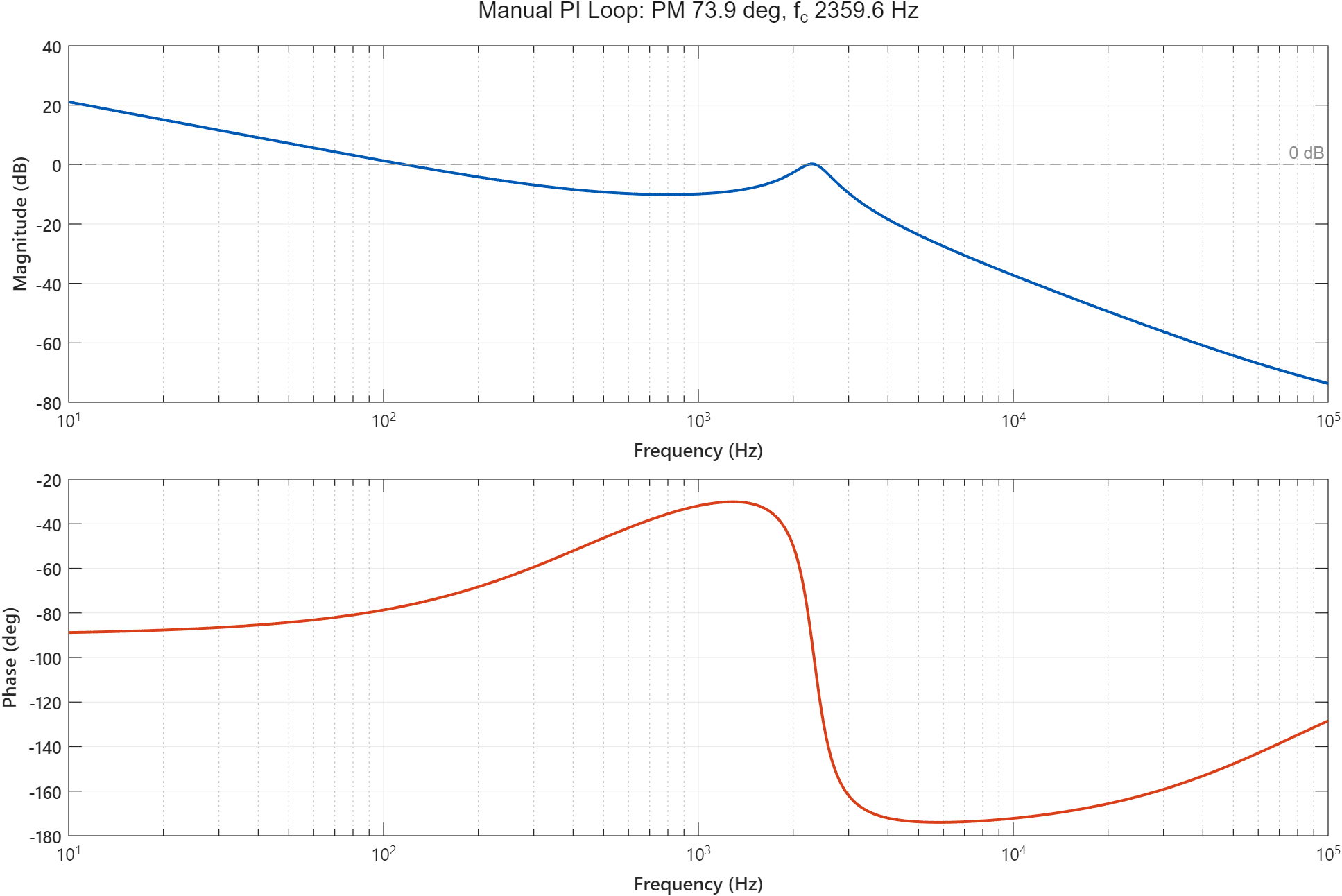
The averaged duty-to-output plant has a complex pole pair at
−1739.849 ± j14526.197 rad/s and an ESR zero at −500000 rad/s. With the
manual PI gains Kp = 0.02 and Ki = 60, the nominal averaged loop has
73.877° phase margin and a 2359.620 Hz gain crossover frequency.
The manual averaged controller's deliberately severe line test produces a
1.144 V undershoot for 12 V to 10 V and a 2.597 V overshoot for 10 V to
14 V. Both responses remain finite and settle, but they show that line
feedforward or a different large-signal control strategy would be needed for
a hardware-oriented design.
KiCad validation
KiCad CLI 10.0.4 reports zero schematic ERC errors, zero PCB DRC errors, and
zero PCB unconnected items. The full PCB report intentionally retains warning
findings for missing courtyards, silkscreen over copper, installed-library
comparison, and schematic/PCB field or flat-net-name parity. No DRC category
is ignored. See
Documentation/kicad_design_notes.md
for exact counts and limitations.
Running the models
Run MATLAB/buck_parameters.m.
Open a model from the Simulink folder.
Run the simulation and open the voltage and current scopes.
To reproduce the configured load profile and validate every Simulink model:
validate_project(true) updates and simulates every .slx model, checks
recorded signals for finite values, validates the three load operating
points, measures both voltage transitions, and regenerates
Results/load_transient_response.png. Simulink cache and code-generation
files are redirected to the system temporary directory.
To run the complete project validation—including control analysis, every
Simulink model, averaged and switching closed-loop operating cases, transient
tests, and optimization-assisted PI tuning—start a clean MATLAB session and
run:
matlab
addpath('MATLAB')
report = run_all_validations();
For one persistent, uninterrupted MATLAB R2025b record, run this command from
the repository root in PowerShell:
A successful run exits normally and ends the log with
FULL_VALIDATION_PASS. The checked-in log is a software-validation record,
not a hardware test log.
The models were made in MATLAB R2025b using Simulink and Simscape Electrical.
Repository files
MATLAB/buck_parameters.m: design calculations and workspace values
A Brushless DC Motor controller board. The design is inspired and is compatible with Odrive project (https://github.com/madcowswe/ODriveHardware) except that this one has a single channel.
Kestrel 4in1: 6S 4-in-1 ESC running stock AM32 on four STM32G071s, with 24 CSD18540 FETs, LM5109B drivers and battery current sensing. 48 x 52 mm 6-layer KiCad 10 board, DRC clean, with gerbers, BOM, CPL and STEP.
VF_Motor_Driver is an open hardware power distribution board, designed to be part of a larger modular system. This design is based in part on the OpenFFBoard TMC4671 driver board, licensed under the GNU General Public…
A completely from-scratch, bare-metal implementation of Field-Oriented Control (FOC) tailored for ultra-low inductance (3 µH) drone motors (e.g., A2212).
BLDC Motor Driver hardware and firmware project including power stage, gate driver, protection circuits, and control firmware for sensor-based and/or sensorless BLDC motors.
It measures 100 × 70 mm and has 2 copper layers, 1.6 mm thick.
What parts does the STM32 Buck Converter use?
31 parts, built around the STM32G431RBT6, LM5109BSD, TPS7A1633DGN and CSD18540Q5B. The full list of its parts is on this page, with links to each part's symbol and footprint where PCBKit's library has them.
Where can I download the STM32 Buck Converter KiCad files?
From the MAC-75/STM32-Synchronous-Buck-Converter repository on GitHub, at the commit this page was made from: the board is KiCad/STM32_Buck_Converter.kicad_pcb and its schematic KiCad/STM32_Buck_Converter.kicad_sch. PCBKit opens the board in the browser, with nothing to install.
Can I use the STM32 Buck Converter design in my own project?
Its repository publishes it under the MIT licence: you may reuse it on that licence's terms (keep the author's notice, and for a copyleft licence share your changes alike).