2 layers57.5 × 42.8 mm
Black Body Heater Control
DylanLockyer/Black_Body
Electrical system for black body MKID tester
52 parts1MIT

 DylanLockyer/Black_Body1
Electrical system for black body MKID tester
Black Body Temperature Sensor PCB is an open-source printed circuit board by DylanLockyer, from the DylanLockyer/Black_Body repository on GitHub, published under the MIT licence. It is a 6-layer board of 62 × 77 mm with 217 parts on 196 nets, routed with 1,491 tracks and 724 vias.
It is built around the STM32G431RBT6, LT1008S8#PBF and OPA376AIDBVR-MS, with the AD8421ARZ, LM334M and ABM8G-25.000MHZ-18-D2Y-T among its other parts. Its parts include 98 capacitors, 70 resistors, 20 ICs, 9 connectors and 6 transistors. It belongs with the sensors and measurement boards and the STM32 boards of this library.


Two-layer circuit board carrying the ESP32 microcontroller and all heater control electronics: current source, voltage/current sensing, and power supply. See the firmware README for how this board is driven, and the root README for overall project context.
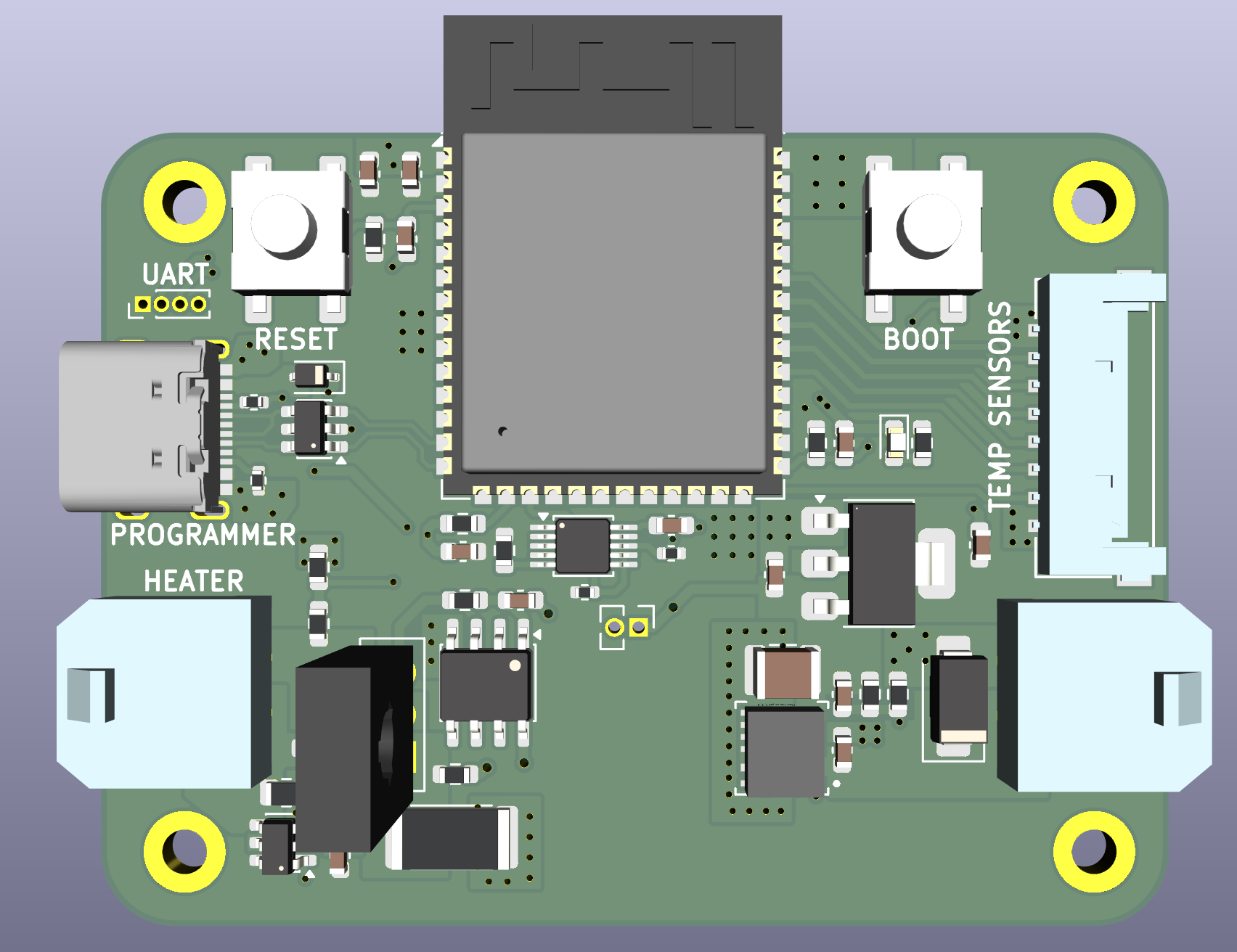
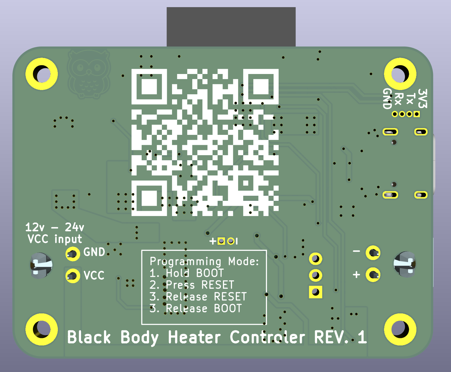
Schematic: Black_Body_Heater_Control_Schematic.pdf
An ESP32 was chosen for its high pin count and WiFi support, letting it self-host a web page for displaying readings and controlling the heater. It interfaces with the temperature sensor board over SPI (3 CS lines for 3 temperature probes). The microcontroller is programmed over USB, with exposed pads for UART programming as a fallback. Board-to-board interfacing uses Molex connectors (504050-0891 for the SPI link) since they could be sampled for free.
The heater is 4x 10Ω resistors in series (40Ω total). A maximum output power of 10W requires a peak 12V at 0.3A, measured with a shunt resistor + amplifier (current) and a voltage divider (voltage), both read by the ESP32's internal 12-bit ADC. This gives a theoretical current step of 100µA (max 0.66A range) and a voltage step of 8mV (max 36V range).
The original design used an N-channel MOSFET with PWM to control heater voltage. Due to concerns about PWM noise interfering with the sensor board's measurements, this was replaced with an analog current source instead.
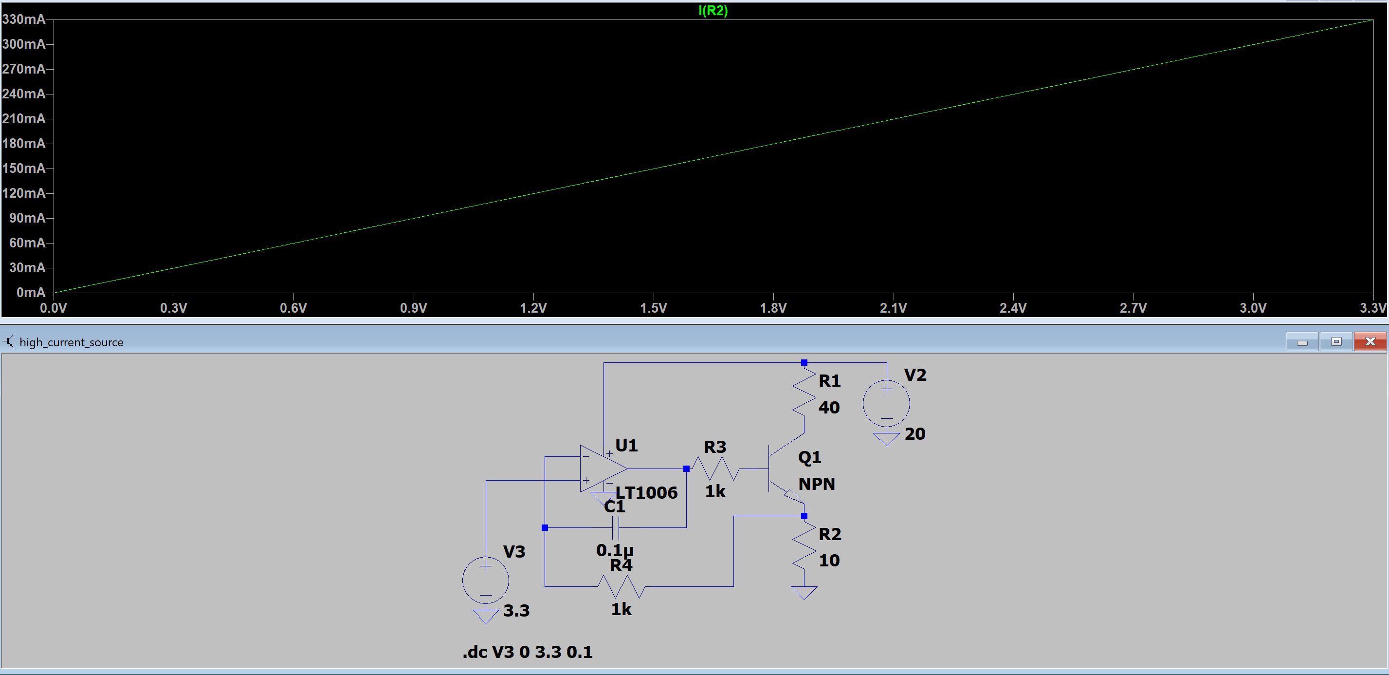
Output current vs. input voltage for the analog current source. A BJT and op-amp generate the current output, driven by a DAC that the microcontroller controls.
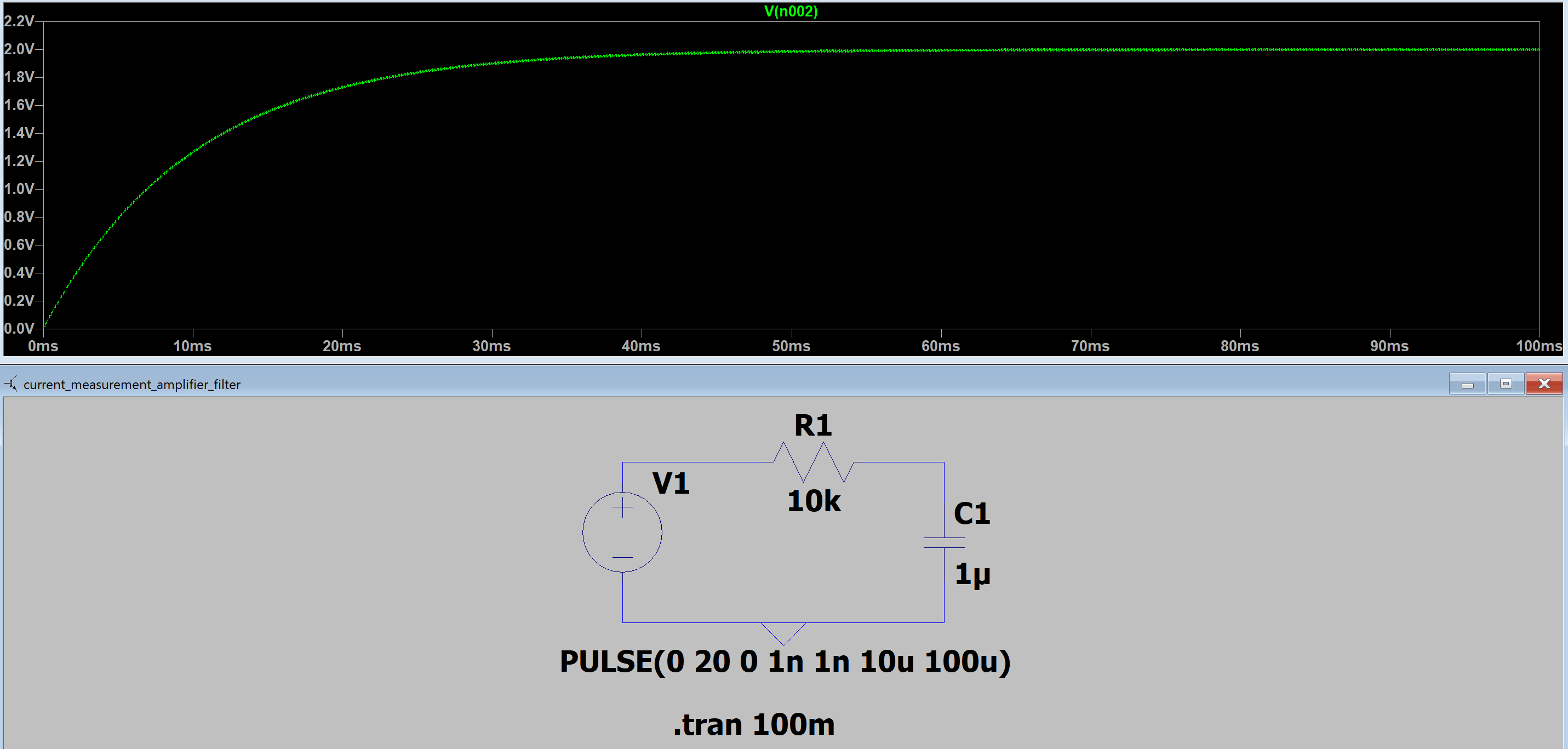
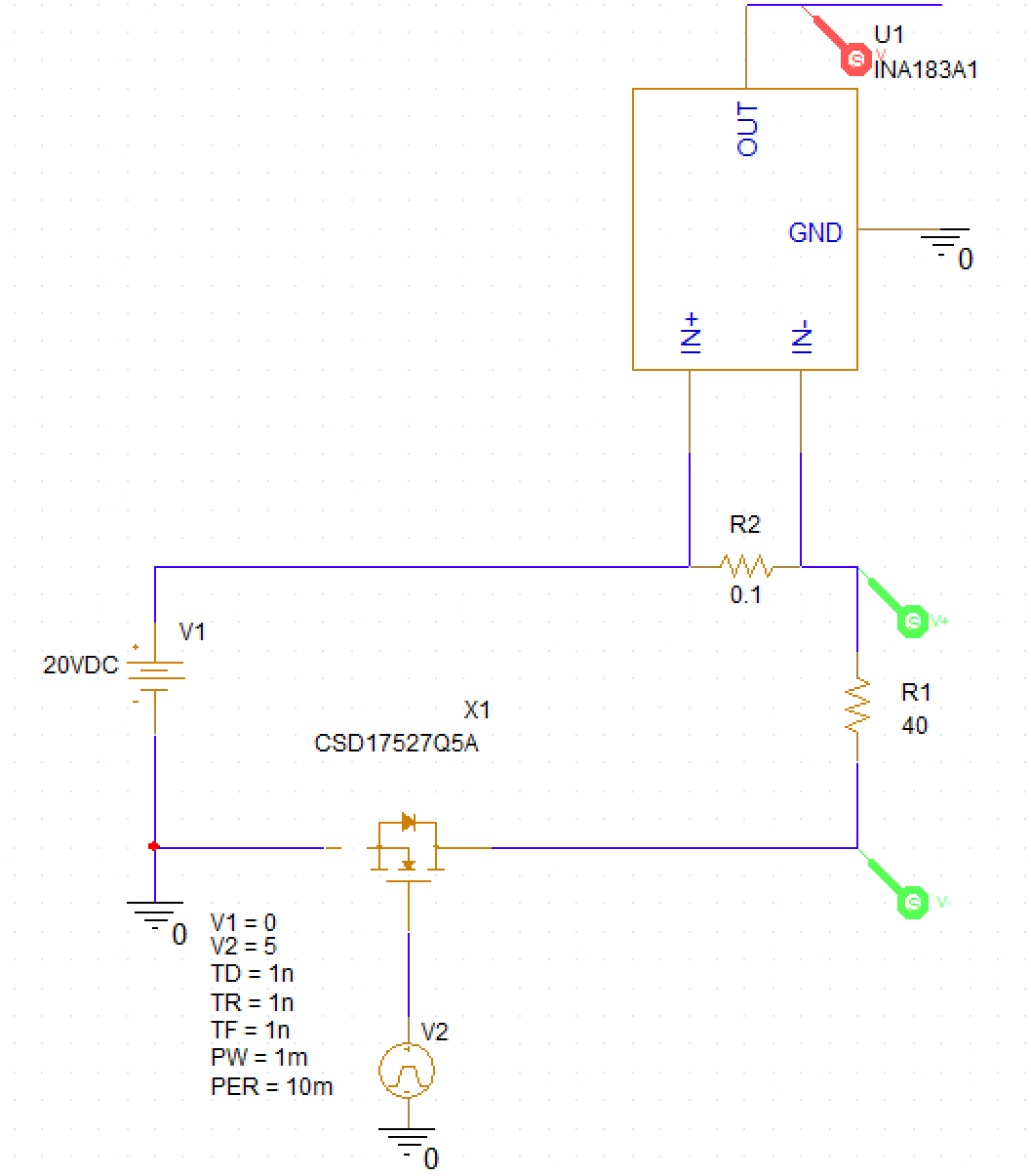
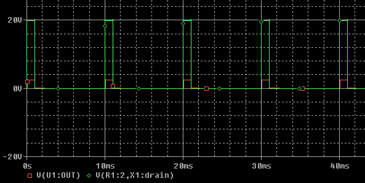
The shunt resistor is 100mΩ with a 50V/V amplifier gain, giving 2.5V output at 0.5A and 0.25V at 0.05A. A low-pass filter on the amplifier output is largely unnecessary now that PWM isn't used, but is kept (with an easy jumper to bypass it) in case it's needed. Simulated filtering of a 10% duty cycle, 10kHz PWM signal on 20V is shown below:
The board receives 12V from an external power supply. A buck converter steps this down to 5V at 2A, followed by an LDO to 3.3V for a clean, low-noise supply to the microcontroller and ADC.
Revision 1: Changed buck converter to newer module as the rev 0 as it broke and fried both boards.
Heater and buck converter behavior were validated in PSpice before layout (see Simulations/Heater_Controller_PCB):
| Qty | Value | Footprint | References |
|---|---|---|---|
| 48 | 2u2 | Capacitor_SMD:C_0402_1005Metric | C201, C202, C203, C204, C205, C206, C207, C208, C209, C210, C211, C212, C213, C214, C215, C216 +32 |
| 29 | 0.1uf | Capacitor_SMD:C_0603_1608Metric | C502, C503, C504, C505, C506, C507, C508, C509, C510, C511, C512, C513, C514, C515, C516, C517 +13 |
| 26 | 5.1k | Resistor_SMD:R_0402_1005Metric | R201, R202, R203, R204, R205, R206, R207, R208, R301, R302, R303, R304, R401, R402, R403, R404 +10 |
| 8 | 10uf | Capacitor_SMD:C_0603_1608Metric | C601, C602, C606, C607, C609, C614, C615, C712 |
| 6 | 10k | Resistor_SMD:R_0603_1608Metric | R412, R413, R505, R506, R703, R704 |
| 6 | TMUX1112PWR | Package_SO:TSSOP-16_4.4x5mm_P0.65mm | Q201, Q202, Q301, Q401, Q402, Q403 |
| 6 | TestPoint | TestPoint:TestPoint_Pad_2.0x2.0mm | TP401, TP402, TP403, TP601, TP602, TP603 |
| 5 | 4.7uf | Capacitor_SMD:C_0603_1608Metric | C608, C610, C611, C612, C613 |
| 5 | OPA376xxDBV | Package_TO_SOT_SMD:SOT-23-5 | U501, U502, U503, U504, U509 |
| 4 | 180k | Resistor_SMD:R_0603_1608Metric | R602, R603, R607, R609 |
| 3 | 1.33k | Resistor_SMD:R_0603_1608Metric | R210, R211, R705 |
| 3 | 10M | Resistor_SMD:R_0603_1608Metric | R305, R502, R504 |
| 3 | 33.2k | Resistor_SMD:R_0603_1608Metric | R407, R605, R608 |
| 3 | 500 | Resistor_SMD:R_0603_1608Metric | R406, R606, R616 |
| 2 | 10nf | Capacitor_SMD:C_0603_1608Metric | C604, C605 |
| 2 | 13.3k | Resistor_SMD:R_0603_1608Metric | R212, R213 |
| 2 | 134k | Resistor_SMD:R_0603_1608Metric | R214, R215 |
| 2 | 28pf | Capacitor_SMD:C_0603_1608Metric | C703, C705 |
| 2 | 448k | Resistor_SMD:R_0603_1608Metric | R611, R613 |
| 2 | 50 | Resistor_SMD:R_0603_1608Metric | R501, R503 |
| 2 | 50k | Resistor_SMD:R_0603_1608Metric | R612, R614 |
| 2 | 569k | Resistor_SMD:R_0603_1608Metric | R601, R604 |
| 2 | AD8421ARZ | Package_SO:SOIC-8_3.9x4.9mm_P1.27mm | U505, U506 |
| 2 | LM334M | Package_SO:SOIC-8_3.9x4.9mm_P1.27mm | U201, U301 |
| 2 | SW_MEC_5E | -switch:430471035826 | SW701, SW702 |
| 2 | Screw_Terminal_01x02 | -connector:CUI_TB002-500-02BE | J401, J402 |
| 1 | 1.33M | Resistor_SMD:R_0603_1608Metric | R216 |
| 1 | 100M | Resistor_SMD:R_0603_1608Metric | R308 |
| 1 | 100k | Resistor_SMD:R_0603_1608Metric | R307 |
| 1 | 133 | Resistor_SMD:R_0603_1608Metric | R209 |
| 1 | 1M | Resistor_SMD:R_0603_1608Metric | R310 |
| 1 | 1N457 | Diode_THT:D_DO-35_SOD27_P7.62mm_Horizontal | D201 |
| 1 | 1N5819WS | Diode_SMD:D_SOD-323 | D701 |
| 1 | 1uf | Capacitor_SMD:C_0603_1608Metric | C603 |
| 1 | 2.7k | Resistor_SMD:R_0603_1608Metric | R311 |
| 1 | 200pf | Capacitor_SMD:C_0603_1608Metric | C309 |
| 1 | 22.6k | Resistor_SMD:R_0603_1608Metric | R306 |
| 1 | 220nf | Capacitor_SMD:C_0603_1608Metric | C501 |
| 1 | 226k | Resistor_SMD:R_0603_1608Metric | R309 |
| 1 | 22uf | Capacitor_SMD:C_0603_1608Metric | C715 |
| 1 | 4.99 | Resistor_SMD:R_0603_1608Metric | R405 |
| 1 | 436500200 | -connector:436500200 2-pin | P601 |
| 1 | 5040500891 | -connector:CONN_5040500891_MOL | J702 |
| 1 | 7.5k | Resistor_SMD:R_0603_1608Metric | R610 |
| 1 | ABM8G-25.000MHZ-18-D2Y-T | -oscillators:ABM8G-25.000MHZ-18-D2Y-T | U702 |
| 1 | ADS131M04xPW | Package_SO:TSSOP-20_4.4x6.5mm_P0.65mm | U507 |
| 1 | AMS1117-3.3 | Package_TO_SOT_SMD:SOT-223-3_TabPin2 | U705 |
| 1 | Conn_01x02_Pin | Connector_PinHeader_2.54mm:PinHeader_1x02_P2.54mm_Vertical | J601 |
| 1 | Conn_01x04_Pin | Connector_PinHeader_2.54mm:PinHeader_1x04_P2.54mm_Vertical | J704 |
| 1 | Conn_01x06_Pin | Connector_PinHeader_2.54mm:PinHeader_1x06_P2.54mm_Vertical | J701 |
| 1 | ISO7762FDBQ | Package_SO:SSOP-16_3.9x4.9mm_P0.635mm | U508 |
| 1 | LOGO | LOGO | G*** |
| 1 | LT1004-1.2 | Package_SO:SOIC-8_3.9x4.9mm_P1.27mm | D301 |
| 1 | LT1008 | Package_SO:SOIC-8_3.9x4.9mm_P1.27mm | U302 |
| 1 | LT3042xMSE | Package_SO:MSOP-10-1EP_3x3mm_P0.5mm_EP1.68x1.88mm | U603 |
| 1 | LT3094xMSE | Package_SO:MSOP-12-1EP_3x4.039mm_P0.65mm_EP1.651x2.845mm | U602 |
| 1 | LTC3260xMSE | Package_SO:MSOP-16-1EP_3x4.039mm_P0.5mm_EP1.651x2.845mm | U601 |
| 1 | RED | LED_SMD:LED_0603_1608Metric | D702 |
| 1 | SMAJ24A | Diode_SMD:D_SMA | D601 |
| 1 | STM32G431RBTx | Package_QFP:LQFP-64_10x10mm_P0.5mm | U704 |
| 1 | TXU0304 | Package_SO:TSSOP-14_4.4x5mm_P0.65mm | U701 |
| 1 | USBLC6-2SC6 | Package_TO_SOT_SMD:SOT-23-6 | U703 |
| 1 | USB_C_Receptacle_USB2.0_16P | -connector:UJ20-C-H-G-SMT-1-P16-TR | J703 |
| 1 | pogo programmer | -connector:pogo_programmer | P701 |
DylanLockyer/Black_Body
Electrical system for black body MKID tester

BetzDrive/interface-board
Power and signal conditioning board for the Betz Drive system


kongr45gpen/POQUITO-panels
Solar panels with a Magnetorquer for a PocketQube


afkiwers/GroundTruth
KiCad 10 plugin and CLI that simulates return currents, EMI, power stages, PDN impedance and thermal rise with a field solver, and suggests vias and design fixes.


It measures 62 × 77 mm and has 6 copper layers, 1.56 mm thick.
217 parts, built around the STM32G431RBT6, LT1008S8#PBF, OPA376AIDBVR-MS and AD8421ARZ. The full list of its parts is on this page, with links to each part's symbol and footprint where PCBKit's library has them.
From the DylanLockyer/Black_Body repository on GitHub, at the commit this page was made from: the board is Circuit Boards/Black_Body_Temperature_Sensor_PCB/Black_Body_Temperature_Sensor_PCB.kicad_pcb and its schematic Circuit Boards/Black_Body_Heater_Control_PCB/Black_Body_Heater_Control.kicad_sch. PCBKit opens the board in the browser, with nothing to install.
Its repository publishes it under the MIT licence: you may reuse it on that licence's terms (keep the author's notice, and for a copyleft licence share your changes alike).