2 layers36.6 × 63.6 mm

 fgihl/usb-c-one
Small one port USB-C hub, similar to YKUSH XS, but uses USB-C connectors
Llm kicad is an open-source printed circuit board by fgihl, from the fgihl/usb-c-one repository on GitHub. It is a 4-layer board of 50 × 40 mm with 100 parts on 93 nets, routed with 634 tracks and 177 vias.
It is built around the SN74LVC1G125DBVR-TP, CP2102N-A02-GQFN28 and TPD4E05U06DQAR, with the CH334F, LTV-217D and TLV76733DRVR among its other parts. Its parts include 32 resistors, 24 capacitors, 12 ICs, 6 diodes and 4 transistors.


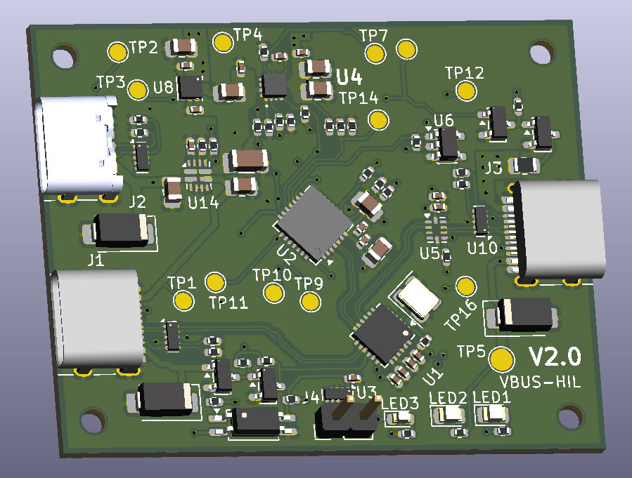
A bench device that sits between a Raspberry Pi and a USB-C device under test (DUT). Host software gets controlled access to the DUT's USB 2.0 data, USB-C CC attachment and 5 V VBUS, so it can emulate unplugging and reconnecting the DUT without touching its cable.
It is intended for controlled hardware-in-the-loop (HIL) lab rigs. It is not a general-purpose USB-C charger, dock or power-distribution product.
libgpiod on the standard Linux cp210x gpiochip.| Ref | Role |
|---|---|
| J1 | USB-C upstream to the Raspberry Pi: USB 2.0 data, and fallback VBUS |
| J2 | USB-C 5 V power input (power only, no data). Preferred over J1 |
| J3 | USB-C downstream to the DUT: switched data, CC and VBUS |
| J4 | External opto-buffered control line |
flowchart LR
  J1[J1 USB-C to Pi] -->|D+/D-| H[CH334F USB 2.0 hub]
  J1 -->|VBUS_UP| MUX[TPS2121 priority mux]
  J2[J2 5 V input] -->|VBUS_PWR| MUX
  MUX --> VSYS((VSYS))
  VSYS --> LDO[TLV76733 3.3 V LDO]
  LDO --> H
  H -->|port 1, fixed| C[CP2102N GPIO control]
  H -->|port 2| SW[TS3USB221A data switch]
  SW --> J3[J3 USB-C to DUT]
  LDO --> RP[Rp buffer] --> J3
  VSYS --> EF[TPS259470L eFuse] -->|VBUS_HIL| J3
  C --> EF
  C --> SW
C --> RP| Function | Part |
|---|---|
| USB 2.0 hub | CH334F |
| Control IC | CP2102N-A02 (7 GPIO) |
| Power mux | TPS2121 |
| J3 eFuse | TPS259470L |
| Data switch | TS3USB221A |
| 3.3 V LDO | TLV76733 |
| Rp buffer | SN74LVC1G125 |
| ESD | TPD4E05U06 |
Board: 4 layers, 50 x 40 mm, top-side SMT, designed for JLCPCB assembly.
| Case | Power source | Use |
|---|---|---|
| A. Pi-powered | J1 only | Low-current DUTs only. Enumeration, data path and low-power control. |
| B. External 5 V | J2, with the Pi supplying data on J1 | Normal mode for high-current tests. The source must supply the DUT load plus about 0.1 A board consumption (at least 3.5 A for a 3 A DUT). |
| C. Split-cable | External 5 V on J1 VBUS, Pi supplies data and GND | Qualified fixtures only. The Pi-side VBUS must be isolated from the external supply. |
J1 and J2 accept regulated 5 V only. Sustained 12 V or 20 V input is outside the product contract.
Software owns the state machine. The hardware does not detect DUT attach and does not enforce source capability.
Before a high-current test, confirm that J2 is powering the board. Turn J3 VBUS off before planned J2 removal. The CP2102N GPIO map, configuration image and a control-service example are in architecture/architecture_final.md section 6.
| Path | Contents |
|---|---|
| product_description.md | Product requirements, operating cases, accepted limitations, acceptance checks |
| architecture/architecture_final.md | Schematic-level architecture, power budget, GPIO map, BOM, risks, prototype tests |
| architecture/schematic_overview.md | Schematic overview |
| architecture/pcb_floor_plan.md | PCB floor plan and layout constraints |
| llm-kicad/ | KiCad 10 project (hierarchical schematic, PCB, custom symbols) |
| llm-kicad/schematic_review_report.md | Schematic review report and finding log |
| tools/ | Audit and helper scripts |
The schematic sheets are 01_power_cc, 02_usb_hub_control, 03_dut_interface and 04_test_validation. Open llm-kicad/llm-kicad.kicad_pro in KiCad 10.
tools/audit_schematic.py checks symbol pin numbers against placed footprint pad numbers, schematic versus PCB footprint sync, Value text versus the JLCPCB catalogue part, and Datasheet coverage. It exits non-zero if the pin/pad or footprint-sync checks fail.
python3 tools/audit_schematic.pyThe full list and the release acceptance checks are in product_description.md sections 7 to 9.
Hardware revision V2.0. Five units are built, identified 1-5, each programmed
with the CP2102N configuration image carrying Release Version 2.00
(0x0200) — the host reads this back as bcdDevice = 0x0200, though only
after the board has been power-cycled. All five units were verified
2026-10-14: correct configuration image and power-up safe state, VBUS rising in
18–21 ms, and a USB mass-storage DUT enumerating at J3 on connect and dropping
off on disconnect. Per-unit evidence is in code/fleet-record.tsv. The unit ID is carried in the CP2102N USB
serial descriptor (0001-0005); the manufacturer and product strings stay at
the Silicon Labs defaults, so the serial descriptor is what distinguishes one
unit from another. See
architecture/architecture_final.md
section 6.3 for the Release Version and serial-number policies and the per-unit
read-back gate.
Before release, see the open items in the schematic review report and the mandatory prototype tests in architecture/architecture_final.md section 10. The CP2102N must be programmed with the configuration image before use.
| Qty | Value | Footprint | References |
|---|---|---|---|
| 9 | 100nF | Capacitor_SMD:C_0402_1005Metric | C6, C10, C13, C20, C22, C24, C26, C27, C28 |
| 5 | 1k | Resistor_SMD:R_0402_1005Metric | R27, R47, R50, R51, R52 |
| 4 | 100k | Resistor_SMD:R_0402_1005Metric | R45, R46, R48, R49 |
| 4 | 10k | Resistor_SMD:R_0402_1005Metric | R28, R33, R34, R35 |
| 4 | 4.7uF 25V | Capacitor_SMD:C_0805_2012Metric | C1, C3, C23, C25 |
| 4 | BSS138P,215 | Package_TO_SOT_SMD:SOT-23 | Q2, Q3, Q6, Q7 |
| 4 | MountingHole | MountingHole:MountingHole_2.2mm_M2 | H1, H2, H3, H4 |
| 3 | 10uF 25V | Capacitor_SMD:C_0805_2012Metric | C9, C11, C12 |
| 3 | SMAJ6.5A | Diode_SMD:D_SMA | D1, D2, D3 |
| 3 | TPD4E05U06DQA | Package_SON:USON-10_2.5x1.0mm_P0.5mm | U3, U9, U10 |
| 2 | 10k 0402 | Resistor_SMD:R_0402_1005Metric | R38, R79 |
| 2 | 1uF 25V | Capacitor_SMD:C_0402_1005Metric | C19, C21 |
| 2 | 4.7k | Resistor_SMD:R_0402_1005Metric | R5, R6 |
| 2 | 5.1k | Resistor_SMD:R_0402_1005Metric | R1, R2 |
| 2 | 5.1k 0402 | Resistor_SMD:R_0402_1005Metric | R3, R4 |
| 2 | TYPE-C-31-M-12 | Connector_USB:USB_C_Receptacle_HRO_TYPE-C-31-M-12 | J1, J3 |
| 1 | +3V3 | TestPoint:TestPoint_Pad_D1.5mm | TP4 |
| 1 | 100k 0402 | Resistor_SMD:R_0402_1005Metric | R37 |
| 1 | 100nF 0402 | Capacitor_SMD:C_0402_1005Metric | C18 |
| 1 | 100pF | Capacitor_SMD:C_0402_1005Metric | C2 |
| 1 | 10uF 0805 25V | Capacitor_SMD:C_0805_2012Metric | C17 |
| 1 | 12k | Resistor_SMD:R_0402_1005Metric | R30 |
| 1 | 18k 0402 | Resistor_SMD:R_0402_1005Metric | R39 |
| 1 | 1k 0402 | Resistor_SMD:R_0402_1005Metric | R40 |
| 1 | 1nF | Capacitor_SMD:C_0402_1005Metric | C14 |
| 1 | 1uF 0402 25V | Capacitor_SMD:C_0402_1005Metric | C16 |
| 1 | 22k | Resistor_SMD:R_0402_1005Metric | R43 |
| 1 | 24k | Resistor_SMD:R_0402_1005Metric | R32 |
| 1 | 330R 0402 | Resistor_SMD:R_0402_1005Metric | R76 |
| 1 | 470R 0805 | Resistor_SMD:R_0805_2012Metric | R36 |
| 1 | 47k | Resistor_SMD:R_0402_1005Metric | R44 |
| 1 | 47uF 10V | Capacitor_SMD:C_1206_3216Metric | C5 |
| 1 | 49.9k | Resistor_SMD:R_0402_1005Metric | R29 |
| 1 | 931R 0.1% | Resistor_SMD:R_0402_1005Metric | R31 |
| 1 | CH334F | Package_DFN_QFN:QFN-24-1EP_4x4mm_P0.5mm_EP2.7x2.7mm | U1 |
| 1 | CP2102N-A02-GQFN28 | Package_DFN_QFN:QFN-28-1EP_5x5mm_P0.5mm_EP3.25x3.25mm | U2 |
| 1 | Conn_01x02_Socket | Connector_PinHeader_2.54mm:PinHeader_1x02_P2.54mm_Vertical | J4 |
| 1 | Crystal 12MHz | Crystal:Crystal_SMD_3225-4Pin_3.2x2.5mm | Y1 |
| 1 | EN_HIL | TestPoint:TestPoint_Pad_D1.5mm | TP8 |
| 1 | EXT_02 | TestPoint:TestPoint_Pad_D1.5mm | TP16 |
| 1 | EXT_I01 | TestPoint:TestPoint_Pad_D1.5mm | TP9 |
| 1 | Green | LED_SMD:LED_0805_2012Metric | LED1 |
| 1 | HIL_CC_EN_N | TestPoint:TestPoint_Pad_D1.5mm | TP12 |
| 1 | HIL_DATA_EN_N | TestPoint:TestPoint_Pad_D1.5mm | TP11 |
| 1 | HIL_VBUS_EN | TestPoint:TestPoint_Pad_D1.5mm | TP10 |
| 1 | LTV-217 | Package_SO:SOP-4_4.4x2.6mm_P1.27mm | U15 |
| 1 | Red | LED_SMD:LED_0603_1608Metric | LED3 |
| 1 | SN74LVC1G125DBVR | Package_TO_SOT_SMD:SOT-23-5 | U6 |
| 1 | TLV76733DRVR | Package_SON:WSON-6-1EP_2x2mm_P0.65mm_EP1x1.6mm_ThermalVias | U8 |
| 1 | TPD4E05U06DQAR | Package_SON:USON-10_2.5x1.0mm_P0.5mm | U11 |
| 1 | TPS2121RUXR | Package_DFN_QFN:Texas_VQFN-HR-12_2x2.5mm_P0.5mm | U14 |
| 1 | TPS259470LRPWR | TPS259470ARPWR:TPS259470LRPWR | U4 |
| 1 | TS3USB221A | Package_DFN_QFN:Texas_UQFN-10_1.5x2mm_P0.5mm | U5 |
| 1 | TYPE-C-31-M-17 | Connector_USB:USB_C_Receptacle_HRO_TYPE-C-31-M-17 | J2 |
| 1 | U4_ILM | TestPoint:TestPoint_Pad_D1.5mm | TP7 |
| 1 | VBUS_HIL | TestPoint:TestPoint_Pad_D2.0mm | TP5 |
| 1 | VBUS_HIL_SNS | TestPoint:TestPoint_Pad_D1.5mm | TP14 |
| 1 | VBUS_PWR | TestPoint:TestPoint_Pad_D1.5mm | TP2 |
| 1 | VBUS_UP | TestPoint:TestPoint_Pad_D1.5mm | TP1 |
| 1 | VSYS | TestPoint:TestPoint_Pad_D1.5mm | TP3 |
| 1 | Yellow | LED_SMD:LED_0805_2012Metric | LED2 |


Gamecard/k2-plus-cm5
K2 Plus CM5 – Creality K2 Plus mit Upstream-Klipper auf einem Raspberry Pi CM5

antmicro/scalenode-cm4-baseboard
Baseboard for Raspberry Pi 4 Compute Module optimized for clustering

M17-Project/Module_17
M17 modem board for 9600-baud capable radios


BayLibre/Copilot-extension-triple-usb-2.0
Extension board for Copilot Lite providing 3 USB 2.0 passthrough channels.

filliformes/pandore
pandore is an open-source digital audio instrument protyping platform based on the LattePanda Mu.
It measures 50 × 40 mm and has 4 copper layers, 1.58 mm thick.
100 parts, built around the SN74LVC1G125DBVR-TP, CP2102N-A02-GQFN28, TPD4E05U06DQAR and CH334F. The full list of its parts is on this page, with links to each part's symbol and footprint where PCBKit's library has them.
From the fgihl/usb-c-one repository on GitHub, at the commit this page was made from: the board is llm-kicad/llm-kicad.kicad_pcb and its schematic llm-kicad/01_power_cc.kicad_sch. PCBKit opens the board in the browser, with nothing to install.
Its repository states no licence, so its author keeps all rights: ask fgihl before reusing the design.