4 layers76.5 × 76.9 mm

 feecat/PicoIndustrial14
Industrial Control Module Based on RPI PICO
PicoIndustrial is an open-source printed circuit board by feecat, from the feecat/PicoIndustrial repository on GitHub, published under the GPL-3.0 licence. It is a 2-layer board of 140 × 90 mm with 163 parts on 129 nets, routed with 748 tracks and 175 vias.
It is built around the LM258DR, TPS5430DDAR and LTV-354T, with the CL31A106KBHNNNE, 19-217/BHC-ZL1M2RY/3T and 1N4148W among its other parts. Its parts include 60 resistors, 29 capacitors, 29 diodes, 11 ICs and 8 switches. It belongs with the RP2040 boards of this library.


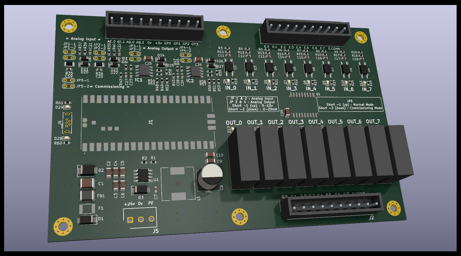
You can buy it at here, for now im in small batch production. Also you can manufactory it by yourself.
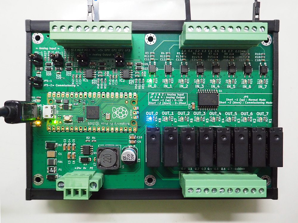
There have 8 digital input, 8 relay output, 2 analog input, 2 analog output and 4 pico pin output.
Digital IO is DC 24v PNP/NPN compatible, Analog IO is 0-10v or 0-20mA selectable.
It was a simple plc or simple controller, Like some they called "arduino plc" controller but more powerfull.
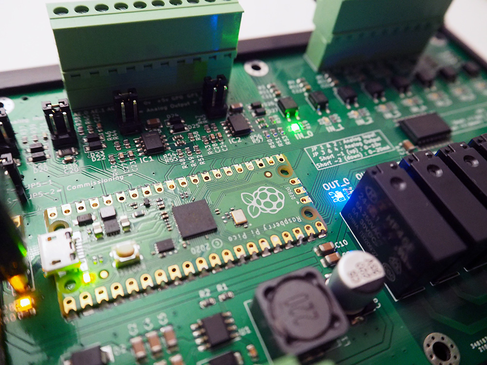
Here is product images, Actually its first that one-shoot successful product for me:
# Example of PicoIndustrial
from machine import Pin, PWM, ADC
from utime import sleep_ms
# Digital I/O Mapping
DI = [Pin(26, Pin.IN, Pin.PULL_DOWN), Pin(22, Pin.IN, Pin.PULL_DOWN), Pin(21, Pin.IN, Pin.PULL_DOWN), Pin(20, Pin.IN, Pin.PULL_DOWN), Pin(19, Pin.IN, Pin.PULL_DOWN), Pin(18, Pin.IN, Pin.PULL_DOWN), Pin(17, Pin.IN, Pin.PULL_DOWN), Pin(16, Pin.IN, Pin.PULL_DOWN)]
DO = [Pin(7, Pin.OUT), Pin(9, Pin.OUT), Pin(10, Pin.OUT), Pin(11, Pin.OUT), Pin(12, Pin.OUT), Pin(13, Pin.OUT), Pin(14, Pin.OUT), Pin(15, Pin.OUT)]
LED = [Pin(25, Pin.OUT), Pin(8, Pin.OUT), Pin(4, Pin.OUT)]
# ADC + DAC, DAC Use PWM to control voltage
AI = [ADC(Pin(28)), ADC(Pin(27))]
AO = [PWM(Pin(5)), PWM(Pin(6))]
AO[0].freq(500000)
AO[1].freq(500000)
# Write Init code here
LED[0].value(1)
# Write Loop code here
while True:
    # Analog IO
    AO[0].duty_u16(32767)
    print(AI[0].read_u16())
    # LED Toggle
    LED[2].value(not LED[2].value())
    # Digital IO
    DO[0].value(DI[0].value())
DO[1].value(not DI[1].value())| Qty | Value | Footprint | References |
|---|---|---|---|
| 20 | 2.2k | Resistor_SMD:R_0603_1608Metric | R19, R20, R21, R22, R23, R24, R25, R26, R27, R28, R29, R30, R31, R32, R33, R34 +4 |
| 13 | 10k | Resistor_SMD:R_0603_1608Metric | R1, R3, R4, R5, R6, R7, R8, R9, R10, R37, R38, R44, R45 |
| 12 | 22nf | Capacitor_SMD:C_0603_1608Metric | C11, C12, C13, C14, C15, C16, C17, C18, C23, C24, C27, C28 |
| 10 | 10uf 50v | Capacitor_SMD:C_1206_3216Metric | C2, C3, C4, C5, C6, C9, C10, C25, C26, C29 |
| 10 | Jumper | TestPoint:TestPoint_2Pads_Pitch2.54mm_Drill0.8mm | JP1-1, JP1-2, JP2-1, JP2-2, JP3-1, JP3-2, JP4-1, JP4-2, JP5-1, JP5-2 |
| 9 | LED_BLUE | LED_SMD:LED_0603_1608Metric | D12, D13, D14, D15, D16, D17, D18, D19, D29 |
| 8 | 1N4148W | Diode_SMD:D_SOD-123 | D20, D21, D22, D23, D24, D25, D26, D27 |
| 8 | 1m | Resistor_SMD:R_0603_1608Metric | R11, R12, R13, R14, R15, R16, R17, R18 |
| 8 | HF46F_024-HS1T | Library:HF46F024HS1T | K1, K2, K3, K4, K5, K6, K7, K8 |
| 8 | LED_GREEN | LED_SMD:LED_0603_1608Metric | D4, D5, D6, D7, D8, D9, D10, D11 |
| 8 | LTV-354T | Package_SO:SO-4_4.4x3.6mm_P2.54mm | U2, U3, U4, U5, U6, U7, U8, U9 |
| 6 | MountingHole_Pad | MountingHole:MountingHole_3.2mm_M3_Pad_Via | H1, H2, H3, H4, H5, H6 |
| 4 | 100k | Resistor_SMD:R_0603_1608Metric | R48, R50, R54, R56 |
| 4 | 20k | Resistor_SMD:R_0603_1608Metric | R49, R51, R55, R57 |
| 4 | 220pf | Capacitor_SMD:C_0603_1608Metric | C19, C20, C21, C22 |
| 4 | 4.7k | Resistor_SMD:R_0603_1608Metric | R39, R40, R46, R47 |
| 3 | WJ15EDGVC-3.81-10P | Library:SHDR10W85P0X381_1X10_3898X700X935P | J2, J3, J4 |
| 2 | 100 | Resistor_SMD:R_0603_1608Metric | R52, R53 |
| 2 | 47 | Resistor_SMD:R_0603_1608Metric | R58, R59 |
| 2 | 510 | Resistor_SMD:R_1206_3216Metric | R35, R36 |
| 2 | LM258D | Library:SOIC127P600X175-8N | IC1, IC2 |
| 2 | SS54 | Diode_SMD:D_SMA | D1, D3 |
| 1 | 10nf | Capacitor_SMD:C_1812_4532Metric | C1 |
| 1 | 10nf 50v | Capacitor_SMD:C_0603_1608Metric | C7 |
| 1 | 220uf 35v | Capacitor_SMD:CP_Elec_8x10 | C8 |
| 1 | 22uh 3A | Inductor_SMD:L_12x12mm_H6mm | L1 |
| 1 | 3.24k | Resistor_SMD:R_0603_1608Metric | R2 |
| 1 | CBW453215U121T | Inductor_SMD:L_1812_4532Metric | FB1 |
| 1 | LED_YELLOW | LED_SMD:LED_0603_1608Metric | D28 |
| 1 | PICO | Library:PICO_HOLE | J1 |
| 1 | SMBJ30CA | Diode_SMD:D_SMB | D2 |
| 1 | TPS5430DDA | Package_SO:TI_SO-PowerPAD-8_ThermalVias | U1 |
| 1 | ULN2803ADWR | Package_SO:SOIC-18W_7.5x11.6mm_P1.27mm | Q1 |
| 1 | USB_B_Micro | Connector_USB:USB_Micro-B_Wuerth_614105150721_Vertical | J6 |
| 1 | WJ15EDGVC-3.81-3P | Library:SHDR12W85P0X381_1X3_4660X700X935P | J5 |
| 1 | mSMD110-33V | Fuse:Fuse_1812_4532Metric | F1 |


yeyintlwin/kicad-board-design
Design a two-layer KiCad PCB entirely from Python scripts - no GUI step, no commercial autorouter


elagil/net-bmp
An Ethernet-connected SWD/JTAG debug adapter (blackmagic probe)

swayerloren/KICAD_ENGINE
AI-assisted KiCad PCB design workflow for schematics, PCB layouts, DRC, BOM/CPL, and fabrication outputs using Codex or Claude.

ConnorRigby/GD32-Devboard
Simple GD32F405 Development board with CAN, SD Card, Lora, BLE and GPS

Galacs/motor-power-poc
A POC PCB to test circuit electrical protections and motor control schemes
It measures 140 × 90 mm and has 2 copper layers, 1.6 mm thick.
163 parts, built around the LM258DR, TPS5430DDAR, LTV-354T and CL31A106KBHNNNE. The full list of its parts is on this page, with links to each part's symbol and footprint where PCBKit's library has them.
From the feecat/PicoIndustrial repository on GitHub, at the commit this page was made from: the board is PicoIndustrial.kicad_pcb and its schematic PicoIndustrial.kicad_sch. PCBKit opens the board in the browser, with nothing to install.
Its repository publishes it under the GPL-3.0 licence: you may reuse it on that licence's terms (keep the author's notice, and for a copyleft licence share your changes alike).