2 layers140 × 90 mm

 NietoSkunk/FlippyDriver10
Driver board for Luminator MAX3000 Flip Dot Panels
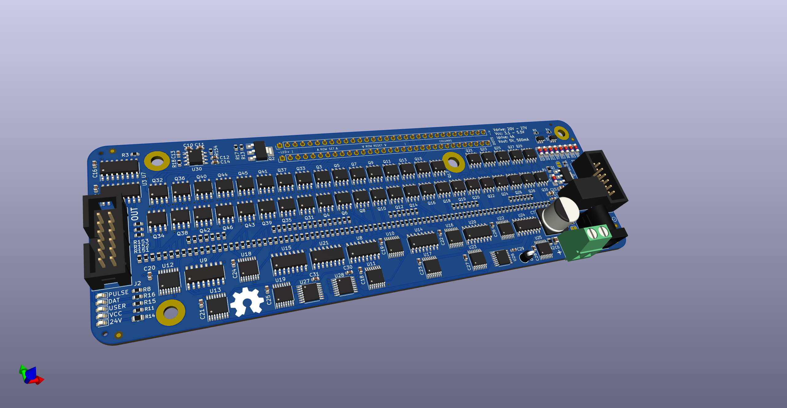
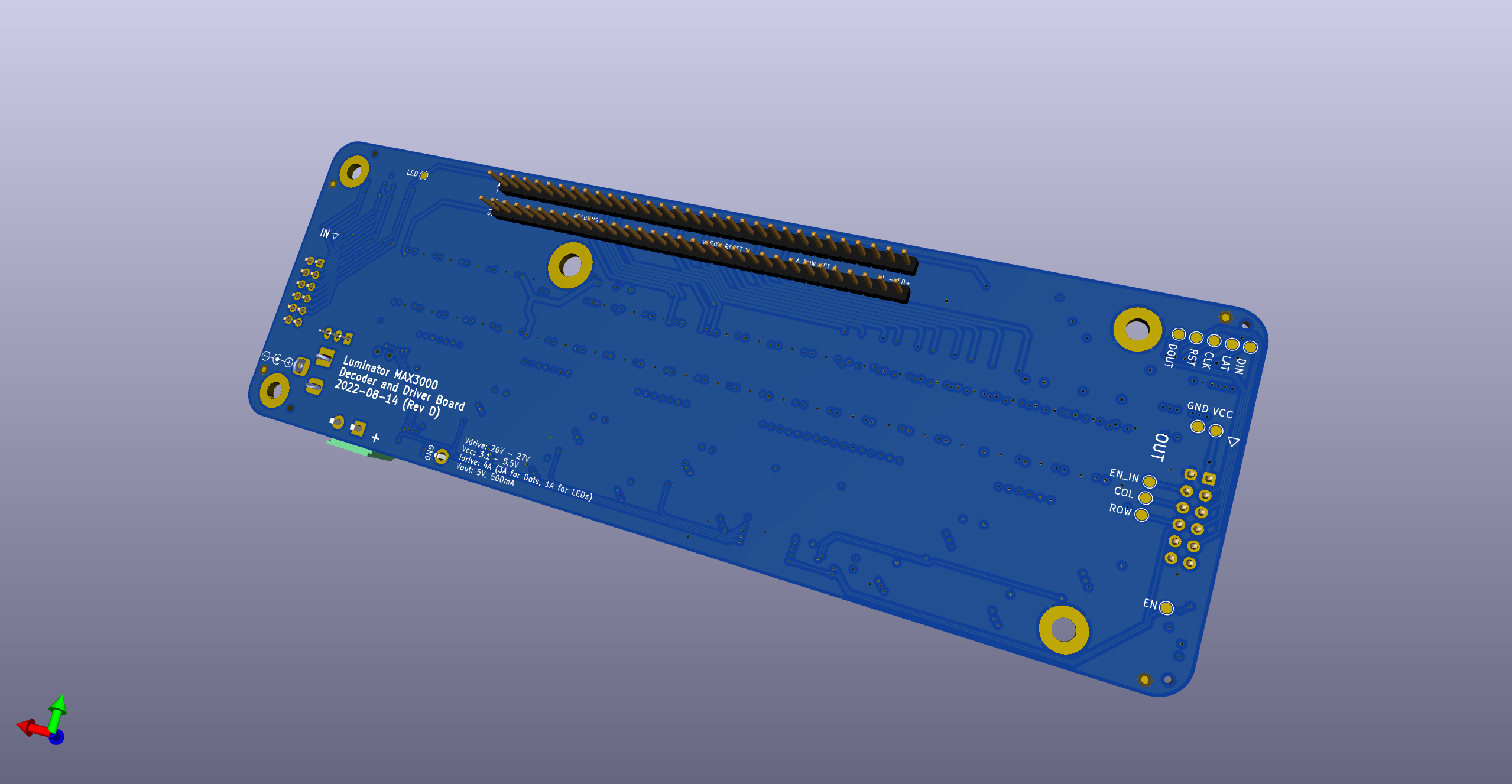
FlippyDriver is an open-source printed circuit board by NietoSkunk, from the NietoSkunk/FlippyDriver repository on GitHub, published under the MIT licence. It is a 4-layer board of 189.4 × 59.1 mm with 344 parts on 379 nets, routed with 3,069 tracks and 374 vias.
It is built around the VX7805-500, 74HC238D and ULN2003ADRG, with the 74HC595, LM393 and CJ431 among its other parts. Its parts include 161 resistors, 55 transistors, 38 capacitors, 30 ICs and 18 diodes.


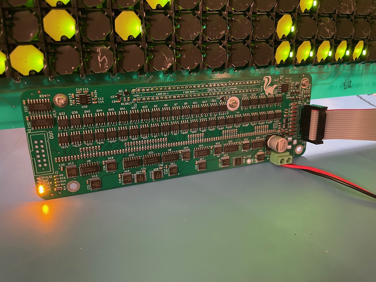
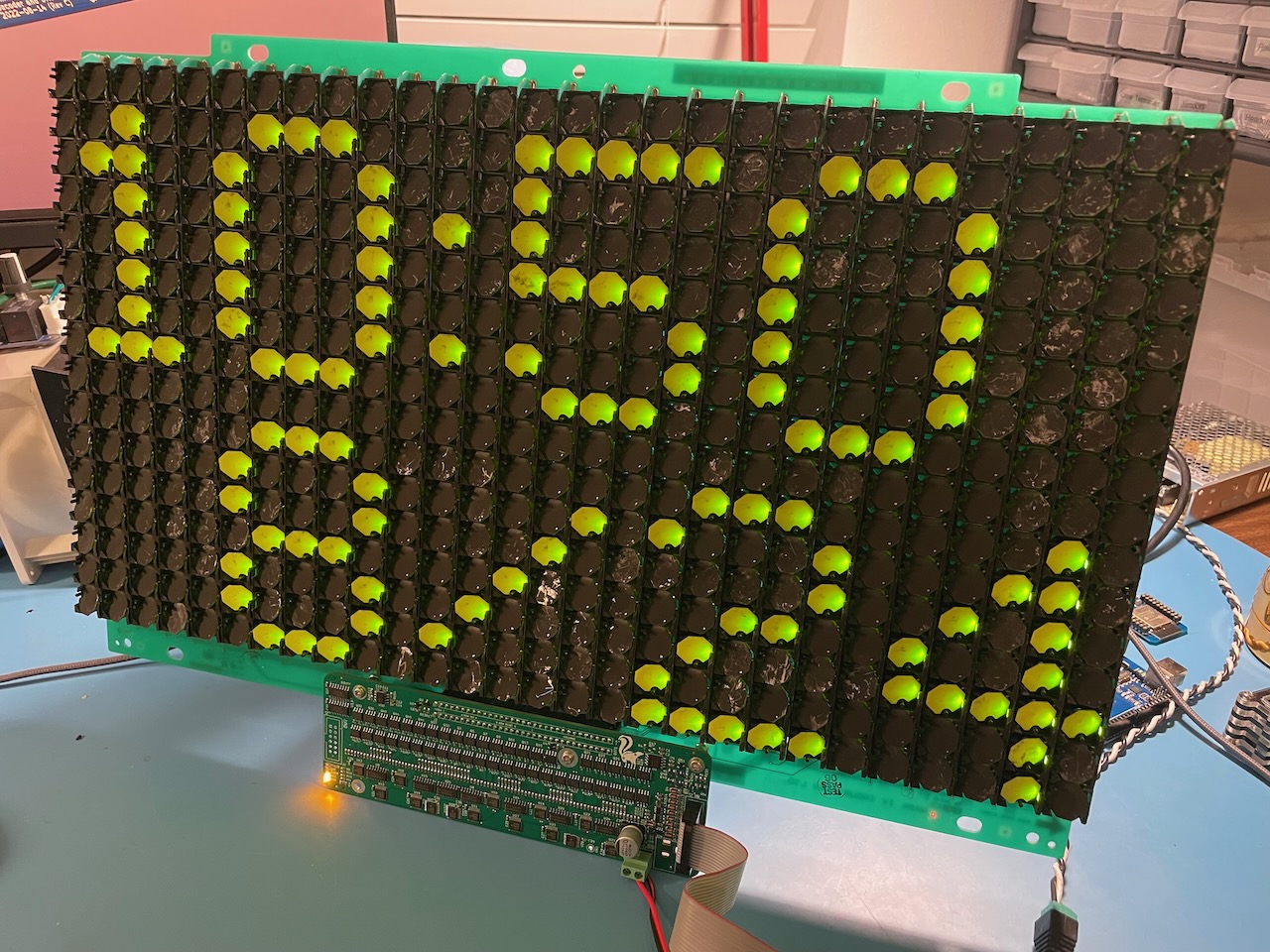
Driver board for Luminator MAX3000 Flip Dot Panels, allowing for chaining multiple panels, 3.3V and 5V tolerant inputs, and LED illumination with PWM dimming.
$ git clone --recurse-submodules git@github.com:NietoSkunk/FlippyDriver.git| Pin | # | # | Pin |
|---|---|---|---|
| VCC | 1 | 2 | GND |
| MOSI | 3 | 4 | PULSE_ENABLE |
| LATCH | 5 | 6 | COL_PULSE_N |
| CLK | 7 | 8 | ROW_PULSE_N |
| RESET | 9 | 10 | LED PWM |
| 5V Return | 11 | 12 | GND |
All logic circuitry is both 3.3V and 5V tolerant, as long as the VCC power rail is at least as high as the logic voltage. The RESET line has a pull-down resistor and is Active-Low. The PULSE_ENABLE pin is active high (i.e. pulse on high level), and the COL and ROW PULSE pins are active low (i.e. pulse on low level).
WARNING: The low side sink drivers must be turned on after the high side, and turned off before the high side. For example, a pulse sequence of ROW Low, COL Low, COL High, ROW High would be used if the row is sourced and the column is grounded in order to set a bit. Damage may occur to the circuit if this order is not maintained!
The 5V Return pin is connected to the output of the 7805 regulator, which allows a board to receive 5V power from the 24V drive power. It is not passed through to other modules, and thus only the first board in the chain has an accessible 5V output. All other boards in the chain do not have the aux output routed anywhere, and they can optionally be depopulated.
| Pin | # | # | Pin |
|---|---|---|---|
| LED- | 1 | 2 | LED- |
| LED+ | 3 | 4 | LED+ |
| ROW_2_RESET | 5 | 6 | ROW_2_SET |
| ROW_4_RESET | 7 | 8 | ROW_4_SET |
| ROW_6_RESET | 9 | 10 | ROW_6_SET |
| ROW_8_RESET | 11 | 12 | ROW_8_SET |
| ROW_10_RESET | 13 | 14 | ROW_10_SET |
| ROW_12_RESET | 15 | 16 | ROW_12_SET |
| ROW_14_RESET | 17 | 18 | ROW_14_SET |
| ROW_16_RESET | 19 | 20 | ROW_16_SET |
| ROW_15_RESET | 21 | 22 | ROW_15_SET |
| ROW_13_RESET | 23 | 24 | ROW_13_SET |
| ROW_11_RESET | 25 | 26 | ROW_11_SET |
| ROW_9_RESET | 27 | 28 | ROW_9_SET |
| ROW_7_RESET | 29 | 30 | ROW_7_SET |
| ROW_5_RESET | 31 | 32 | ROW_5_SET |
| ROW_3_RESET | 33 | 34 | ROW_3_SET |
| ROW_1_RESET | 35 | 36 | ROW_1_SET |
| COL_2 | 37 | 38 | COL_1 |
| COL_4 | 39 | 40 | COL_3 |
| COL_6 | 41 | 42 | COL_5 |
| COL_8 | 43 | 44 | COL_7 |
| COL_10 | 45 | 46 | COL_9 |
| COL_12 | 47 | 48 | COL_11 |
| COL_14 | 49 | 50 | COL_13 |
| COL_16 | 51 | 52 | COL_15 |
| COL_18 | 53 | 54 | COL_17 |
| COL_20 | 55 | 56 | COL_19 |
| COL_22 | 57 | 58 | COL_21 |
| COL_24 | 59 | 60 | COL_23 |
| COL_26 | 61 | 62 | COL_25 |
| COL_28 | 63 | 64 | COL_27 |
Each board contains a pair of 74HC595 shift registers, which are used to select a single pixel to be enabled at a time. This can be driven either directly with GPIO outputs, or using a hardware SPI output. The format of the data is MSB first, clock on high.
The Row and Column decoders are grouped into banks of eight, using 74HC238 3:8 decoders. The Column and Row A2/A1/A0 lines select the output of each bank, and the Column and Row Bank lines select which bank is active. The Row and Column source line switches that output to drive a high side source instead of a low side sink.
The I2C Pullup line is used to enable a set of 4.7kOhm resistors on the I2C bus, which allows a single board in a chain to optionally provide pullups.
The output of the shift register is sent out to the OUT header, and comes in to the next board in the chain on the MOSI line. This allows multiple boards to be controlled at once by shifting 16 bits of data for each board.
| Bit | Function |
|---|---|
| 0 | Column A2 |
| 1 | Column A1 |
| 2 | Column A0 |
| 3 | Row A0 |
| 4 | Row A1 |
| 5 | Row A2 |
| 6 | Row Bank |
| 7 | Column Bank 0 |
| 8 | Column Source |
| 9 | N/C |
| 10 | Row Source |
| 11 | Row Bank |
| 12 | N/C |
| 13 | User LED |
| 14 | N/C |
| 15 | N/C |
| Qty | Value | Footprint | References |
|---|---|---|---|
| 97 | 10k | Resistor_SMD:R_0603_1608Metric | R103, R104, R105, R106, R107, R108, R109, R110, R111, R112, R113, R114, R115, R116, R117, R118 +81 |
| 46 | 1k | Resistor_SMD:R_0603_1608Metric | R13, R100, R101, R102, R119, R120, R121, R122, R123, R124, R125, R126, R143, R144, R145, R146 +30 |
| 44 | AP4606 | Package_SO:SOIC-8_3.9x4.9mm_P1.27mm | Q10, Q11, Q12, Q13, Q14, Q15, Q16, Q17, Q18, Q19, Q20, Q21, Q22, Q23, Q24, Q25 +28 |
| 26 | 0.1u | Capacitor_SMD:C_0603_1608Metric | C2, C10, C16, C18, C19, C20, C21, C22, C23, C24, C25, C26, C27, C28, C29, C30 +10 |
| 14 | 74HC238 | Package_SO:TSSOP-16_4.4x5mm_P0.65mm | U10, U11, U12, U13, U16, U17, U18, U19, U22, U23, U25, U26, U27, U28 |
| 12 | ZMM5V6 | Diode_SMD:D_MiniMELF | D1, D4, D6, D7, D8, D9, D10, D11, D12, D13, D16, D17 |
| 7 | ULN2003ADR | Package_SO:SOIC-16_3.9x9.9mm_P1.27mm | U8, U9, U14, U15, U20, U21, U24 |
| 6 | AO3400A | Package_TO_SOT_SMD:SOT-23 | Q49, Q50, Q51, Q52, Q54, Q55 |
| 5 | AO3401A | Package_TO_SOT_SMD:SOT-23 | Q1, Q2, Q47, Q48, Q53 |
| 4 | 10u | Capacitor_SMD:C_0805_2012Metric | C3, C15, C17, C35 |
| 4 | 220R | Resistor_SMD:R_0603_1608Metric | R2, R8, R11, R15 |
| 4 | 56k,1% | Resistor_SMD:R_0603_1608Metric | R4, R5, R6, R10 |
| 4 | MountingHole_Pad | MountingHole:MountingHole_3.5mm_Pad_TopBottom | H1, H2, H3, H4 |
| 3 | 10k | Resistor_SMD:R_0805_2012Metric | R3, R9, R14 |
| 3 | 1u | Capacitor_SMD:C_0603_1608Metric | C11, C12, C34 |
| 3 | 56k | Resistor_SMD:R_0603_1608Metric | R1, R7, R17 |
| 2 | 0.01u | Capacitor_SMD:C_0603_1608Metric | C13, C14 |
| 2 | 19-213/Y2C-CQ2R2L/3T(CY) | LED_SMD:LED_0603_1608Metric | D3, D14 |
| 2 | 2.4k,1% | Resistor_SMD:R_0603_1608Metric | R12, R159 |
| 2 | 74HC595 | Package_SO:SOIC-16_3.9x9.9mm_P1.27mm | U3, U7 |
| 2 | LM393 | Package_SO:SOIC-8_3.9x4.9mm_P1.27mm | U1, U5 |
| 2 | MCP9700T-ETT | Package_TO_SOT_SMD:SOT-23 | U6, U29 |
| 1 | 19-217/BHC-ZL1M2RY/3T | LED_SMD:LED_0603_1608Metric | D15 |
| 1 | 19-217/GHC-YR1S2/3T | LED_SMD:LED_0603_1608Metric | D2 |
| 1 | 1u | Capacitor_SMD:C_0805_2012Metric | C1 |
| 1 | 220u | Capacitor_SMD:CP_Elec_10x10 | C4 |
| 1 | 24V Input | TerminalBlock_Phoenix:TerminalBlock_Phoenix_MKDS-1,5-2_1x02_P5.00mm_Horizontal | J4 |
| 1 | 24V Input | Connector_BarrelJack:BarrelJack_Horizontal | J5 |
| 1 | 3.6k,1% | Resistor_SMD:R_0603_1608Metric | R160 |
| 1 | 4.7u | Capacitor_SMD:C_1206_3216Metric | C8 |
| 1 | 5.6k,1% | Resistor_SMD:R_0603_1608Metric | R16 |
| 1 | 500mA | Fuse:Fuse_0603_1608Metric | F2 |
| 1 | 5A | Fuse:Fuse_0603_1608Metric | F1 |
| 1 | Board Harness | Nieto_Connector:Luminator_MAX3000 | J3 |
| 1 | CJ431 | Package_TO_SOT_SMD:SOT-23 | U2 |
| 1 | CLK | TestPoint:TestPoint_Pad_D1.5mm | TP1 |
| 1 | COL | TestPoint:TestPoint_Pad_D1.5mm | TP15 |
| 1 | DIN | TestPoint:TestPoint_Pad_D1.5mm | TP11 |
| 1 | DOUT | TestPoint:TestPoint_Pad_D1.5mm | TP3 |
| 1 | Data Harness In | Connector_IDC:IDC-Header_2x06_P2.54mm_Vertical | J1 |
| 1 | Data Harness Out | Connector_IDC:IDC-Header_2x06_P2.54mm_Vertical | J2 |
| 1 | EN | TestPoint:TestPoint_Pad_D1.5mm | TP13 |
| 1 | EN_IN | TestPoint:TestPoint_Pad_D1.5mm | TP7 |
| 1 | GND | TestPoint:TestPoint_Pad_D1.5mm | TP5 |
| 1 | GND | TestPoint:TestPoint_Keystone_5005-5009_Compact | TP6 |
| 1 | JLCJLCJLCJLC | Nieto_Symbol:JLCPCB_OrderNumber | JLCJLCJLCJLC |
| 1 | LAT | TestPoint:TestPoint_Pad_D1.5mm | TP12 |
| 1 | LED | TestPoint:TestPoint_Pad_D1.5mm | TP10 |
| 1 | MountingHole_Pad | MountingHole:MountingHole_4.5mm_Pad_TopBottom | H5 |
| 1 | NCD0805R1 | LED_SMD:LED_0805_2012Metric | D18 |
| 1 | NE555D | Package_SO:SOIC-8_3.9x4.9mm_P1.27mm | U30 |
| 1 | ROW | TestPoint:TestPoint_Pad_D1.5mm | TP14 |
| 1 | RST | TestPoint:TestPoint_Pad_D1.5mm | TP2 |
| 1 | SMAJ33CA | Diode_SMD:D_SMA | D5 |
| 1 | VCC | TestPoint:TestPoint_Pad_D1.5mm | TP4 |
| 1 | VX7805-500 | Converter_DCDC:Converter_DCDC_RECOM_R-78E-0.5_THT | U4 |
The 328 most common of 344 parts.

elagil/net-bmp
An Ethernet-connected SWD/JTAG debug adapter (blackmagic probe)


swayerloren/KICAD_ENGINE
AI-assisted KiCad PCB design workflow for schematics, PCB layouts, DRC, BOM/CPL, and fabrication outputs using Codex or Claude.

Celnardur/rfc_tackle_sensor
Open a git bash terminal in the directory of your choosing and call the following command:

tomrodinger/servomotor
Open-source NEMA-17 integrated servomotor (motor + closed-loop driver + controller + encoder). RS-485, Python/Arduino libraries, MCP server for AI control. Hardware, firmware and software.

kinoshita-lab/MIDI-UART-interface-san
Handy interface PCB for MIDI and microcontrollers.

It measures 189.4 × 59.1 mm and has 4 copper layers, 1.6 mm thick.
344 parts, built around the VX7805-500, 74HC238D, ULN2003ADRG and 74HC595. The full list of its parts is on this page, with links to each part's symbol and footprint where PCBKit's library has them.
From the NietoSkunk/FlippyDriver repository on GitHub, at the commit this page was made from: the board is FlippyDriver.kicad_pcb and its schematic 5V_Reg.kicad_sch. PCBKit opens the board in the browser, with nothing to install.
Its repository publishes it under the MIT licence: you may reuse it on that licence's terms (keep the author's notice, and for a copyleft licence share your changes alike).