2 layers28 × 37.5 mm
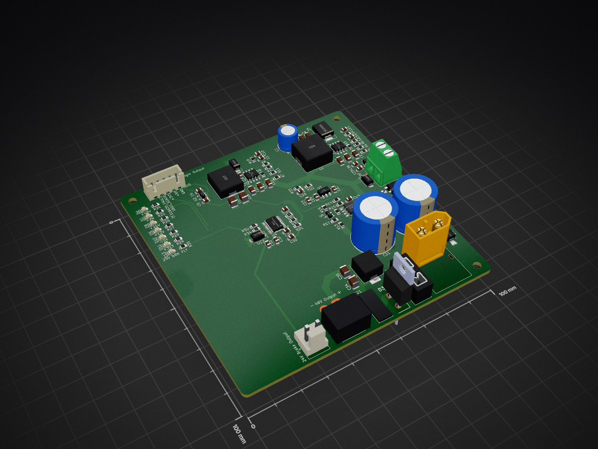
 efebasol/StepperMotorController
Rev A — single-motor bench prototype power board. Feeds the driver board (48 V), the stepper motor brake (24 V) and the logic (5 V / 3V3).
Smc power is an open-source printed circuit board by efebasol, from the efebasol/StepperMotorController repository on GitHub. It is a 4-layer board of 100 × 100 mm with 104 parts on 54 nets, routed with 538 tracks and 139 vias.
It is built around the TPS54360DDA, MCP1416-E/OT and AP2112K-3.3, with the L78L12ACUTR-CN, LM393DR2GH and TL431B among its other parts. Its parts include 35 capacitors, 35 resistors, 13 diodes, 8 ICs and 5 connectors.


Rev A — single-motor bench prototype power board. Feeds the driver board (48 V), the stepper motor brake (24 V) and the logic (5 V / 3V3).
| Block | Key parts | Notes |
|---|---|---|
| 48 V input | J2 XT60 → F1 fuse → D3 MBR10100 (reverse polarity) → R21 NTC MF72 5D13 (inrush, 5 Ω / 5 A) → DM π filter C34 / L4 2.2 µH / C35 → +VM; D4 SMBJ51A TVS and C20/C21 470 µF bulk on +VM | EMI filter #65 (CMC dropped: no 10 A part in stock, noise is mostly DM). LM74700 ideal diode deferred (#60) |
| Brake chopper | IC1 LM393 + U6 TL431B (±0.3 %, REF–K via R36 0 Ω), Q1 AOD4126, U5 MCP1416 gate driver, R16 RX24 50 W 33 Ω (off-board, J1), D5 SS510 flyback | Turn-on 54.14–55.23 V, turn-off 52.27–53.32 V (0.1 % divider) → PSU max ≤ 52 V. Capacity ≈ 1.66 A |
| 12 V LDO | U7 L78L12 (fed from 24 V) | Gate-driver supply only, not on any connector |
| 24 V buck | U1 TPS54360, L1 68 µH | Brake rail. UVLO start ~34 V / stop ~32 V |
| 24 V brake eFuse | U4 TPS16630, R30 12k → ILIM ≈ 1.5 A, UVLO ≈ 20 V / OVP ≈ 30 V, auto-retry | D13 = fault LED (PGOOD low), FLT# → J5 pin 5 (firmware #66) |
| 5 V buck | U3 TPS54360, L2 22 µH, 2×22 µF X7R out (C16, C27), comp. R10 4.22k / C18 27 nF / C17 220 pF | UVLO start ~34 V / stop ~32 V |
| 3V3 LDO | U2 AP2112K-3.3 | max ~200 mA (SOT-23-5 thermal); bigger LDO deferred (#61) |
| VBUS sense | R22 100k / R23 3.9k + 100 nF | 48 V → 1.80 V, ~82 V → 3.08 V. Firmware scaling #63 |
| Indicators | D6–D11 rail LEDs (48V, VM, 24V, 12V, 5V, 3V3), ~1.5 mA each | Silkscreen label next to each LED (#44) |
Design calculations: docs/power-design-notes.md
Board-to-board by cables (no stacking / backplane).
| Ref | Part | Function | Pinout |
|---|---|---|---|
| J2 | XT60PW-M | 48 V IN | 1: +48V · 2: GND |
| J3 | XT30PW-F | 48 V OUT (driver) | 1: VM · 2: GND |
| J4 | JST B2P-VH | 24 V BRAKE | 1: +24V · 2: GND |
| J5 | JST B5B-XH-A | LOGIC (main board) | 1: GND · 2: +5V · 3: +3V3 · 4: VBUS_SENSE · 5: TPS16630_FLT# |
| J1 | KF128 5.08 mm | Brake resistor R16 (off-board) | – |
Main-board side: 1 kΩ series resistor at the MCU ADC pin for VBUS_SENSE; one pull-up for FLT# (open-drain, active-low).
4 layers, 1.6 mm, JLCPCB.
| Layer | Copper | Use |
|---|---|---|
| L1 (F.Cu) | 2 oz | Power |
| L2 (In1.Cu) | 1 oz | Solid GND plane — never split (buck switching loops sit on top of it) |
| L3 (In2.Cu) | 1 oz | Signal + GND fill (keep it solid: it is the return path for L4) |
| L4 (B.Cu) | 2 oz | Power + signal |
48 V, 24 V and SW nodes are routed on the 2 oz outer layers only (inner 1 oz layers can't carry or dissipate that current). Vias between L1 and L4 are fine — current flows in the plated barrel.
Order note: JLC's inner-layer default is 0.5 oz — select 1 oz explicitly.
Values sized with IPC-2221 for 2 oz outer copper, ΔT ≈ 20 °C. Empty cells inherit Default.
| Net class | Clearance | Track width | Via size | Via hole | Nets / notes |
|---|---|---|---|---|---|
PWR_48V | 0.6 mm | 2.5 mm | 1.0 mm | 0.5 mm | 48 V bus. Main 10 A path (input → output connector) as pour where possible (10 A on 2 oz needs ≥2.4 mm) |
SW_NODE | 0.6 mm | 1.0 mm | – | – | Buck switch nodes (SW_24V, SW_5V, pattern *SW_*). Swing 0–48 V → 48 V clearance. Keep copper area minimal |
BOOT_NODE | 0.6 mm | 0.4 mm | – | – | Bootstrap nodes (BOOT_24V, BOOT_5V, pattern *BOOT_*). Rides on SW (up to ~SW + 8 V) → 48 V clearance, low current |
PWR_24V | 0.25 mm | 0.8 mm | 0.8 mm | 0.4 mm | 24 V brake rail (motor brakes). Buck max 3 A → ≥0.45 mm |
PWR_5V | 0.2 mm | 0.5 mm | 0.6 mm | 0.3 mm | 5 V logic rail; also +12V (L78L12 → MCP1416 gate driver, low current) |
PWR_3V3 | 0.2 mm | 0.4 mm | 0.6 mm | 0.3 mm | 3V3 LDO output |
GND | 0.2 mm | 0.5 mm | 0.6 mm | 0.3 mm | Mostly planes/pours; tracks only for short links |
Default | 0.2 mm | 0.25 mm | 0.6 mm | 0.3 mm | Signals (FB, comparator, gate drive, …) |
FB nets (FB_24V, FB_5V) stay in Default on purpose — see layout notes below.
Why 0.6 mm: IPC-2221 B2 (external, uncoated, 31–100 V). Between two classes KiCad applies the larger clearance, so every net next to 48 V automatically gets 0.6 mm.
Rules of thumb:
| Constraint | Value | Why |
|---|---|---|
| Min clearance | 0.15 mm | JLC 2 oz outer minimum |
| Min track width | 0.15 mm | JLC 2 oz outer minimum |
| Min via hole | 0.3 mm | |
| Min annular ring | 0.15 mm | |
| Copper to board edge | 0.5 mm |
(version 1)
(rule "High-power nets: outer 2 oz layers only"
  (layer inner)
  (condition "A.NetClass == 'PWR_48V' || A.NetClass == 'PWR_24V' || A.NetClass == 'SW_NODE'")
(constraint disallow track zone))Issues: label power · Project: https://github.com/users/efebasol/projects/12
| Qty | Value | Footprint | References |
|---|---|---|---|
| 6 | 2.2uF, 100V | Capacitor_SMD:C_1206_3216Metric_Pad1.33x1.80mm_HandSolder | C2, C3, C4, C13, C14, C15 |
| 6 | LED green 0805 | LED_SMD:LED_0805_2012Metric_Pad1.15x1.40mm_HandSolder | D6, D7, D8, D9, D10, D11 |
| 3 | 100nF | Capacitor_SMD:C_0805_2012Metric_Pad1.18x1.45mm_HandSolder | C28, C31, C33 |
| 3 | 1uF | Capacitor_SMD:C_0805_2012Metric_Pad1.18x1.45mm_HandSolder | C5, C6, C30 |
| 3 | MountingHole_M3 | MountingHole:MountingHole_3.2mm_M3 | H1, H2, H3 |
| 3 | SS510 | Diode_SMD:D_SMA | D2, D5, D12 |
| 2 | 100nF, 25V | Capacitor_SMD:C_0805_2012Metric_Pad1.18x1.45mm_HandSolder | C1, C12 |
| 2 | 10uF, 50V | Capacitor_SMD:C_1206_3216Metric_Pad1.33x1.80mm_HandSolder | C8, C9 |
| 2 | 18.7kR | Resistor_SMD:R_0805_2012Metric_Pad1.20x1.40mm_HandSolder | R5, R11 |
| 2 | 22µF 25V X7R 1210 | Capacitor_SMD:C_1210_3225Metric_Pad1.33x2.70mm_HandSolder | C16, C27 |
| 2 | 267kR | Resistor_SMD:R_0805_2012Metric_Pad1.20x1.40mm_HandSolder | R3, R9 |
| 2 | 33kΩ | Resistor_SMD:R_0805_2012Metric_Pad1.20x1.40mm_HandSolder | R24, R25 |
| 2 | 470uF 100V | Capacitor_THT:CP_Radial_D16.0mm_P7.50mm | C20, C21 |
| 2 | 523kR | Resistor_SMD:R_0805_2012Metric_Pad1.20x1.40mm_HandSolder | R1, R7 |
| 2 | CL32B225KCJSNNE | Capacitor_SMD:C_1210_3225Metric | C34, C35 |
| 2 | TPS54360DDA | Package_SO:TI_SO-PowerPAD-8_ThermalVias | U1, U3 |
| 1 | 0.1uF | Capacitor_SMD:C_0805_2012Metric_Pad1.18x1.45mm_HandSolder | C23 |
| 1 | 0.33uF | Capacitor_SMD:C_0805_2012Metric_Pad1.18x1.45mm_HandSolder | C22 |
| 1 | 0Ω | Resistor_SMD:R_0805_2012Metric_Pad1.20x1.40mm_HandSolder | R36 |
| 1 | 100kΩ | Resistor_SMD:R_0805_2012Metric_Pad1.20x1.40mm_HandSolder | R22 |
| 1 | 100nF 100V | Capacitor_SMD:C_0805_2012Metric_Pad1.18x1.45mm_HandSolder | C19 |
| 1 | 100nF 25V | Capacitor_SMD:C_0805_2012Metric_Pad1.18x1.45mm_HandSolder | C25 |
| 1 | 10R | Resistor_SMD:R_0805_2012Metric_Pad1.20x1.40mm_HandSolder | R18 |
| 1 | 10k | Resistor_SMD:R_0805_2012Metric_Pad1.20x1.40mm_HandSolder | R20 |
| 1 | 10kR | Resistor_SMD:R_0805_2012Metric_Pad1.20x1.40mm_HandSolder | R15 |
| 1 | 10kΩ | Resistor_SMD:R_0805_2012Metric_Pad1.20x1.40mm_HandSolder | R34 |
| 1 | 10uF | Capacitor_SMD:C_0805_2012Metric_Pad1.18x1.45mm_HandSolder | C32 |
| 1 | 11.5kR | Resistor_SMD:R_0805_2012Metric_Pad1.20x1.40mm_HandSolder | R12 |
| 1 | 12kR | Resistor_SMD:R_0805_2012Metric_Pad1.20x1.40mm_HandSolder | R6 |
| 1 | 12kΩ | Resistor_SMD:R_0805_2012Metric_Pad1.20x1.40mm_HandSolder | R30 |
| 1 | 15kΩ | Resistor_SMD:R_0805_2012Metric_Pad1.20x1.40mm_HandSolder | R26 |
| 1 | 1kR | Resistor_SMD:R_0805_2012Metric_Pad1.20x1.40mm_HandSolder | R19 |
| 1 | 1kΩ | Resistor_SMD:R_0805_2012Metric_Pad1.20x1.40mm_HandSolder | R35 |
| 1 | 1uF 25V | Capacitor_SMD:C_0805_2012Metric_Pad1.18x1.45mm_HandSolder | C26 |
| 1 | 20kΩ | Resistor_SMD:R_0805_2012Metric_Pad1.20x1.40mm_HandSolder | R32 |
| 1 | 220pF, 25V | Capacitor_SMD:C_0805_2012Metric_Pad1.18x1.45mm_HandSolder | C17 |
| 1 | 22nF | Capacitor_SMD:C_0805_2012Metric_Pad1.18x1.45mm_HandSolder | C29 |
| 1 | 22uH | Inductor_SMD:L_Chilisin_BMRF00101040 | L2 |
| 1 | 243kR | Resistor_SMD:R_0805_2012Metric_Pad1.20x1.40mm_HandSolder | R14 |
| 1 | 24pF, 25V | Capacitor_SMD:C_0805_2012Metric_Pad1.18x1.45mm_HandSolder | C10 |
| 1 | 27nF, 25V | Capacitor_SMD:C_0805_2012Metric_Pad1.18x1.45mm_HandSolder | C18 |
| 1 | 2kΩ | Resistor_SMD:R_0805_2012Metric_Pad1.20x1.40mm_HandSolder | R28 |
| 1 | 3.9kΩ | Resistor_SMD:R_0805_2012Metric_Pad1.20x1.40mm_HandSolder | R23 |
| 1 | 348kR | Resistor_SMD:R_0805_2012Metric_Pad1.20x1.40mm_HandSolder | R2 |
| 1 | 36.5kR | Resistor_SMD:R_0805_2012Metric_Pad1.20x1.40mm_HandSolder | R4 |
| 1 | 4.22kR | Resistor_SMD:R_0805_2012Metric_Pad1.20x1.40mm_HandSolder | R10 |
| 1 | 4.75kR | Resistor_SMD:R_0805_2012Metric_Pad1.20x1.40mm_HandSolder | R17 |
| 1 | 4.7uF | Capacitor_SMD:C_0805_2012Metric_Pad1.18x1.45mm_HandSolder | C24 |
| 1 | 40.2kΩ | Resistor_SMD:R_0805_2012Metric_Pad1.20x1.40mm_HandSolder | R33 |
| 1 | 5.1nF, 25V | Capacitor_SMD:C_0805_2012Metric_Pad1.18x1.45mm_HandSolder | C11 |
| 1 | 6.8kΩ | Resistor_SMD:R_0805_2012Metric_Pad1.20x1.40mm_HandSolder | R27 |
| 1 | 60.4kR | Resistor_SMD:R_0805_2012Metric_Pad1.20x1.40mm_HandSolder | R8 |
| 1 | 68uF, 50V | Capacitor_THT:CP_Radial_D8.0mm_P3.50mm | C7 |
| 1 | 68uH | Inductor_SMD:L_SXN_SMDRI125 | L1 |
| 1 | 820Ω | Resistor_SMD:R_0805_2012Metric_Pad1.20x1.40mm_HandSolder | R29 |
| 1 | 953kΩ | Resistor_SMD:R_0805_2012Metric_Pad1.20x1.40mm_HandSolder | R31 |
| 1 | 97.6kR | Resistor_SMD:R_0805_2012Metric_Pad1.20x1.40mm_HandSolder | R13 |
| 1 | AOD4126 | Step Motor Controller:AOD4185 | Q1 |
| 1 | AP2112K-3.3 | Package_TO_SOT_SMD:SOT-23-5 | U2 |
| 1 | B2P-VH | Connector_JST:JST_VH_B2P-VH_1x02_P3.96mm_Vertical | J4 |
| 1 | B5B-XH-A | Connector_JST:JST_XH_B5B-XH-A_1x05_P2.50mm_Vertical | J5 |
| 1 | ETQP4M2R2KVK | Inductor_SMD:L_Panasonic_PCC-M0850M | L4 |
| 1 | KF128-5.08-2P | TerminalBlock_Phoenix:TerminalBlock_Phoenix_MKDS-1,5-2-5.08_1x02_P5.08mm_Horizontal | J1 |
| 1 | Keystone 3568 + 10A mini fuse | Fuse:Fuseholder_Blade_Mini_Keystone_3568 | F1 |
| 1 | L78L12ACUTR | Package_TO_SOT_SMD:SOT-89-3 | U7 |
| 1 | LED red 0805 | LED_SMD:LED_0805_2012Metric_Pad1.15x1.40mm_HandSolder | D13 |
| 1 | LM393DR2G | Step Motor Controller:SOIC127P600X175-8N | IC1 |
| 1 | MBR10100G | Step Motor Controller:TO508P482X997X1956-2P | D3 |
| 1 | MCP1416 | Package_TO_SOT_SMD:SOT-23-5 | U5 |
| 1 | MF72 5D13 | Step Motor Controller:NTC_Disc_D13mm_W5.5mm_P7.5mm | R21 |
| 1 | SMBJ51A | Diode_SMD:D_SMA-SMB_Universal_Handsoldering | D4 |
| 1 | SS310B | Diode_SMD:D_SMB-SMC_Universal_Handsoldering | D1 |
| 1 | TL431B | Package_TO_SOT_SMD:SOT-23-3 | U6 |
| 1 | TPS16630PWPR | Package_SO:HTSSOP-20-1EP_4.4x6.5mm_P0.65mm_EP2.85x4mm | U4 |
| 1 | XT30PW-F | Connector_AMASS:AMASS_XT30PW-F_1x02_P2.50mm_Horizontal | J3 |
| 1 | XT60PW-M | Connector_AMASS:AMASS_XT60PW-M_1x02_P7.20mm_Horizontal | J2 |
It measures 100 × 100 mm and has 4 copper layers, 1.6 mm thick.
104 parts, built around the TPS54360DDA, MCP1416-E/OT, AP2112K-3.3 and L78L12ACUTR-CN. The full list of its parts is on this page, with links to each part's symbol and footprint where PCBKit's library has them.
From the efebasol/StepperMotorController repository on GitHub, at the commit this page was made from: the board is hardware/power/smc_power.kicad_pcb and its schematic hardware/driver/smc_driver.kicad_sch. PCBKit opens the board in the browser, with nothing to install.
Its repository states no licence, so its author keeps all rights: ask efebasol before reusing the design.

jenna2004jna/ESP32-S3-WROOM-1-Custom-PCB-Design
This project presents a custom-designed PCB based on the ESP32-S3-WROOM-1 module, developed for embedded and IoT applications requiring reliable wireless communication, compact layout, and efficient power management.


ChengminLi/AI-PCB-layout
AI agent skill for designing and reviewing power-electronics PCBs, with a human review gate after every step

JimKueneman/TurnoutBoss
This repository contains all the design files, manuals, firmware, production information for the LCC TurnoutBoss Node

kquinsland/modular-rack-mount-power-system
Hardware, firmware, and host tooling for a modular mini-rack power system.

