
2 layers80 × 50 mm
Greaseweazle F7 Plus V2
aerobaticant/Greaseweazle-F7-Plus
My board design for Keir Fraser's Greaseweazle
66 parts30

cog1 is an open-source industrial IoT gateway (hardware and software) built as a motherboard hosting an Orange Pi Zero 3 Linux SBC.
Cog1 is an open-source printed circuit board by diegodemarco, from the diegodemarco/cog1 repository on GitHub, published under the MIT licence. It is a 2-layer board of 115 × 100 mm with 133 parts on 127 nets, routed with 956 tracks and 371 vias.
It is built around the AOZ1284PI, ISO1212DBQ and MAX13487EEA, with the PCA8574D, PCF8523T and ZMM3.0 among its other parts. Its parts include 53 resistors, 26 capacitors, 16 diodes, 7 ICs and 6 connectors. It belongs with the computers and single-board computers and home automation and IoT boards of this library.


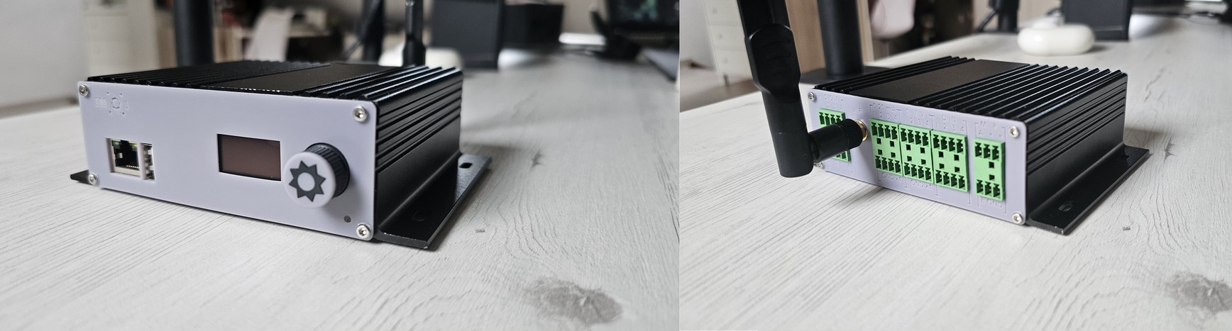
cog1 is an open-source industrial IoT gateway (hardware and software) built as a motherboard hosting an Orange Pi Zero 3 linux SBC (Wiki here).
The cog1 platform currently supports:
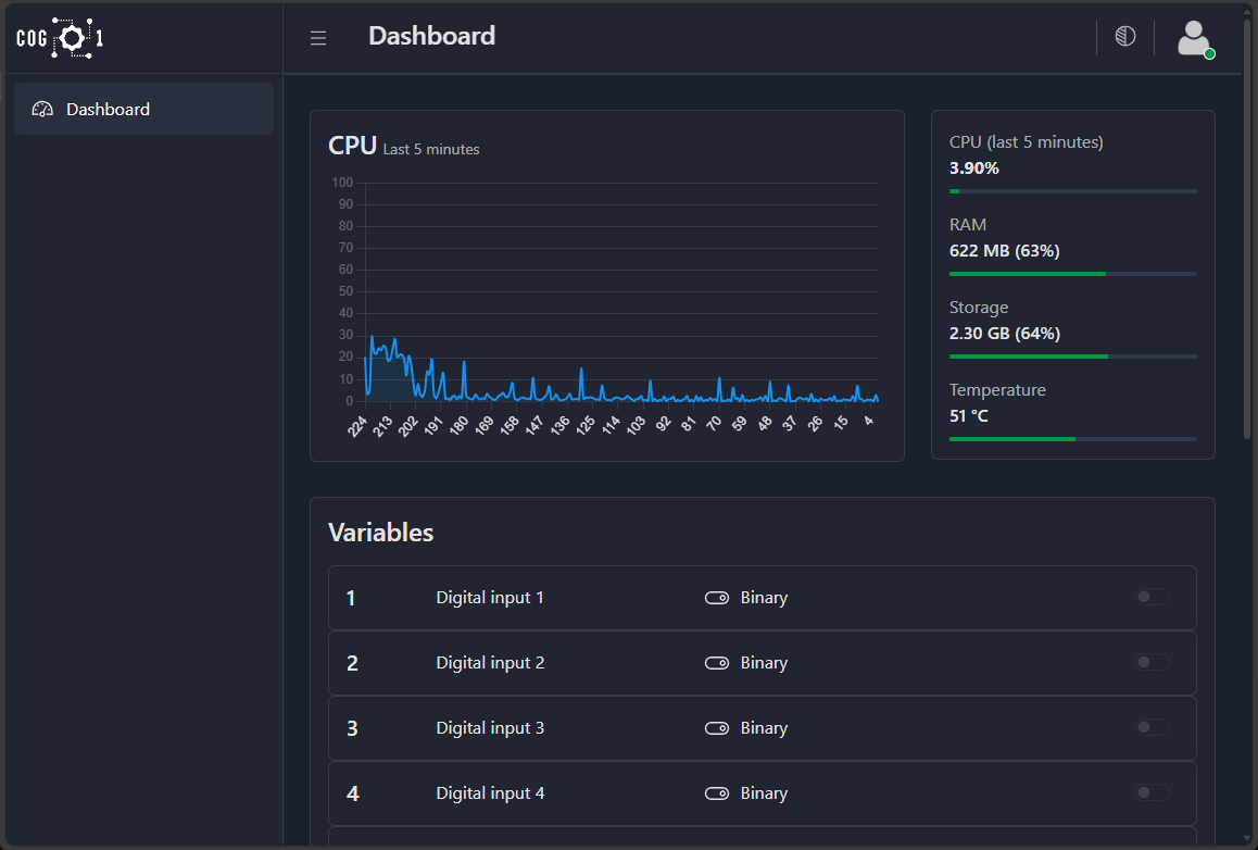 The current software is rather basic, but includes everything needed to fully test the hardware. Additionally, the software already has the correct "architecture", i.e. it is designed as a linux service file that can be started, stopped, etc., and communicates with the hardware through a low-level i/o library created with native code (plain old C).
The front-end (console) is written in Angular, based on the Core-UI admin template, and it communicates with the back-end via web-services, which are already integrated in such a way that creating new controllers/endpoints and consuming them from the front-end is really simple.
The following features are already implemented:
The plan is to continue developing the software so that it can:
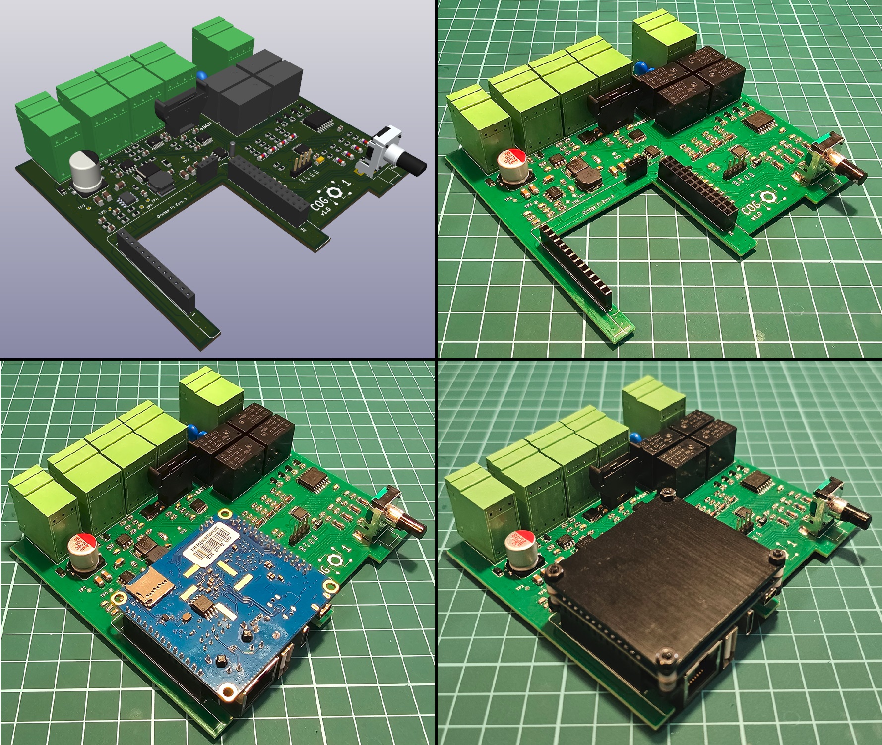
The PCB has been designed using KiCad. It contains everything needed, including a 3D render. All components can be hand-soldered, but a few (essentially the AOZ regulator, the ADC, and the digital input isolators) require a bit of skills, as they are SSOP components.
All capacitors, resistors, etc. are 0805 or bigger, so they can be hand-soldered with little effort. The PCB contains all necessary headers to allow the Orange Pi Zero 3 to be plugged in, inverted.
All components can be found in the usual marketplaces (DigiKey, Mouser, etc.). I strongly advice not using unreliable (i.e. unrealistically cheap) sources for the components, especially the chips, as there is a large market of fake chips that either don't work, or even worse, work erratically.
The enclosure for the cog1 is a rather standard extruded-aluminum case, which can be found online for a few bucks. However, as a 3D printing enthusiast, I ended up designing and printing everything necessary to complete the enclosure:
All designs, done in SolidWorks, are included in this project. I have printed everything with an Elegoo Mars 3 Pro (resin), and expect that all parts would print well on any resin 3D printer. I have not tried to print this on a filament printer, as I believe the quality would not be good enough. When printed in resin, all parts really look production-grade if the proper resin is used.
The main code of the cog1 platform is a .net core application that contains all the necessary components (web services and general logic) to keep the cog1 working. The current version is relatively basic, and only contains those features needed to test the hardware. A web service is in place to provide basic status of the cog1, which is currently used to test the overall reliability of the hardware. All hardware functions have been tested with this software.
This is by far the area that needs the most effort, so that the cog1 can be turned into a fully-functional gateway.
There are a few small portions of the software written in plan old C, and compiled directly in the SBC:
Everything else is c#, so there's no low-level really in the c# code.
The front-end (console) is written in Angular, based on the Core-UI admin template, and it communicates with the back-end via web-services, which are already integrated in such a way that creating new controllers/endpoints and consuming them from the front-end is really simple. While the functionality is relatively limited at the moment, the front-end contains all the necessary building-blocks to be extended easily:
The KiCad project included in the pcb folder contains everything needed to manufacture the pcb. For all prototypes, the pcb was ordered to PCBWay, and then all components were soldered manually. When soldering, I strongly advise mounting the switching power supply first, veryfying the 5V are steady and noiseless, and then mount everything else. This is to prevent blowing up anything if the switching power supply was not mounted correctly.
I'll write a tutorial for this ASAP, but it's pretty straightforward.
| Qty | Value | Footprint | References |
|---|---|---|---|
| 11 | 10K | Resistor_SMD:R_0805_2012Metric | R1, R4, R8, R13, R36, R37, R38, R39, R43, R46, R47 |
| 9 | 100nF | Capacitor_SMD:C_0805_2012Metric | C1, C3, C4, C5, C6, C14, C18, C20, C21 |
| 8 | 9.53K 1% | Resistor_SMD:R_0805_2012Metric | R16, R20, R23, R26, R29, R32, R35, R42 |
| 8 | ZMM3.0 | Diode_SMD:D_MiniMELF | D4, D5, D6, D7, D8, D9, D10, D11 |
| 6 | TestPoint | TestPoint:TestPoint_Pad_D1.0mm | TP1, TP2, TP3, TP4, TP5, TP6 |
| 5 | 10K 1% | Resistor_SMD:R_0805_2012Metric | R10, R28, R31, R34, R41 |
| 5 | 10nF | Capacitor_SMD:C_0805_2012Metric | C16, C23, C24, C25, C26 |
| 5 | 330R | Resistor_SMD:R_0805_2012Metric | R14, R15, R19, R22, R25 |
| 5 | BC807 | Package_TO_SOT_SMD:SOT-23 | Q1, Q2, Q3, Q4, Q5 |
| 4 | 255R 1% | Resistor_SMD:R_0805_2012Metric | R27, R30, R33, R40 |
| 4 | 30.1K 1% | Resistor_SMD:R_0805_2012Metric | R17, R18, R21, R24 |
| 4 | 560R | Resistor_SMD:R_0805_2012Metric | R5, R6, R48, R49 |
| 4 | B72207S0301K103 | Varistor:RV_Disc_D7mm_W4.5mm_P5mm | RV1, RV2, RV3, RV4 |
| 4 | LL4148 | Diode_SMD:D_MiniMELF | D2, D13, D14, D15 |
| 4 | PR5-5V-200-1A | DMUtils:PR5-5V-200-1A | K1, K2, K3, K4 |
| 4 | VL0831510000G | DMUtils:VL0831510000G | CN2, CN3, CN4, CN5 |
| 3 | 100R | Resistor_SMD:R_0805_2012Metric | R2, R3, R7 |
| 3 | 10uF 50V | Capacitor_SMD:C_1206_3216Metric_Pad1.33x1.80mm_HandSolder | C8, C9, C10 |
| 3 | 1K | Resistor_SMD:R_0805_2012Metric | R44, R45, R57 |
| 3 | 47uF 10V | Capacitor_SMD:C_1206_3216Metric_Pad1.33x1.80mm_HandSolder | C11, C12, C13 |
| 2 | ISO1212 | Package_SO:SSOP-16_3.9x4.9mm_P0.635mm | U2, U4 |
| 1 | 1.2K 1% | Resistor_SMD:R_0805_2012Metric | R58 |
| 1 | 100uF 50V | Capacitor_SMD:CP_Elec_10x12.6 | C7 |
| 1 | 10R 1/2W | Resistor_SMD:R_1206_3216Metric_Pad1.30x1.75mm_HandSolder | R59 |
| 1 | 10uF 6.3V | Capacitor_SMD:C_0805_2012Metric | C2 |
| 1 | 1uF | Capacitor_Tantalum_SMD:CP_EIA-3216-10_Kemet-I_Pad1.58x1.35mm_HandSolder | C22 |
| 1 | 255R | Resistor_SMD:R_0805_2012Metric | R56 |
| 1 | 32.768 KHz | Crystal:Crystal_C26-LF_D2.1mm_L6.5mm_Vertical | Y1 |
| 1 | 330pF 50V | Capacitor_SMD:C_0805_2012Metric | C19 |
| 1 | 47K | Resistor_SMD:R_0805_2012Metric | R11 |
| 1 | 52K 1% | Resistor_SMD:R_0805_2012Metric | R9 |
| 1 | 56pF | Capacitor_SMD:C_0805_2012Metric | C15 |
| 1 | 820pF | Capacitor_SMD:C_0805_2012Metric | C17 |
| 1 | 82K | Resistor_SMD:R_0805_2012Metric | R12 |
| 1 | ADC128D818 | Package_SO:TSSOP-16_4.4x5mm_P0.65mm | U12 |
| 1 | AOZ1284PI | DMUtils:AOZ1284PI | U5 |
| 1 | B560C-13-F | Diode_SMD:D_SMC | D3 |
| 1 | BH-50B-1 | DMUtils:BH-50B-1 | BATT1 |
| 1 | Conn_01x04_Pin | Connector_PinHeader_2.54mm:PinHeader_1x04_P2.54mm_Vertical | J1 |
| 1 | INL-3AW30 | LED_SMD:LED_0805_2012Metric_Pad1.15x1.40mm_HandSolder | LED1 |
| 1 | LOGO | DMUtils:cog1_logo | G*** |
| 1 | MAX13487E | Package_SO:SOIC-8_3.9x4.9mm_P1.27mm | U10 |
| 1 | OPI-ZERO-3 | DMUtils:OPI-ZERO-3 | U$1 |
| 1 | PCA8574D | Package_SO:SOIC-16W_7.5x10.3mm_P1.27mm | U3 |
| 1 | PCF8523T | Package_SO:SOIC-8_3.9x4.9mm_P1.27mm | U1 |
| 1 | PEC12R-2120F-S0012 | DMUtils:BOURNS_PEC_HORZ_20 | ENC1 |
| 1 | SM712 | Package_TO_SOT_SMD:SOT-23-3 | D12 |
| 1 | SRN8040TA-4R7M | DMUtils:Bourns_SRN8040TA | L1 |
| 1 | SS2040LL_R1_00001 | Diode_SMD:D_SOD-123F | D1 |
| 1 | VL0631510000G | DMUtils:VL0631510000G | CN1 |
It measures 115 × 100 mm and has 2 copper layers, 1.6 mm thick.
133 parts, built around the AOZ1284PI, ISO1212DBQ, MAX13487EEA and PCA8574D. The full list of its parts is on this page, with links to each part's symbol and footprint where PCBKit's library has them.
From the diegodemarco/cog1 repository on GitHub, at the commit this page was made from: the board is pcb/cog1.kicad_pcb and its schematic pcb/analog_inputs.kicad_sch. PCBKit opens the board in the browser, with nothing to install.
Its repository publishes it under the MIT licence: you may reuse it on that licence's terms (keep the author's notice, and for a copyleft licence share your changes alike).
aerobaticant/Greaseweazle-F7-Plus
My board design for Keir Fraser's Greaseweazle

DanielCusi/MoonJelly-robotics-PCB
Robotics PCB designed for Eurobot used by Wolvineers.

MaverickUK/HDDSynth
Recreate the sound of mechanical spinning HDDs on retro PCs that use a solid state drive


javierveras/projectav-telemetry-pdb-2026
Our power distribution and telemetry system's hardware, firmware, and technical documentation.

