2 layers114.3 × 101.6 mm
ATMEGA16M1
brandon-martinez/jgb
The microcontroller present on this board, and the software which runs on it should eventually be integrated into each node which must communicate via the CAN bus.
65 parts
 brandon-martinez/jgb
The microcontroller present on this board, and the software which runs on it should eventually be integrated into each node which must communicate via the CAN bus.
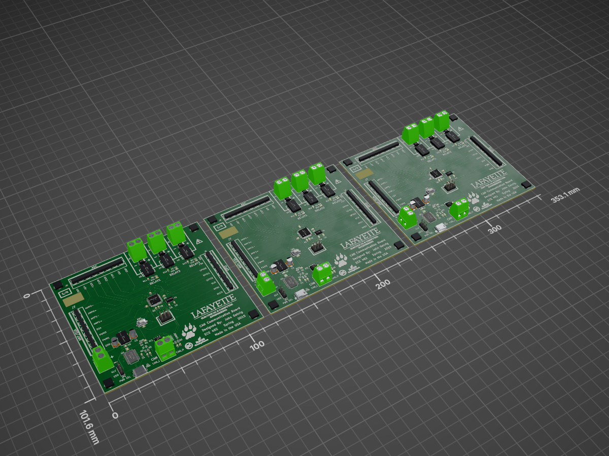
ATMEGA16M1 panel is an open-source printed circuit board by brandon-martinez, from the brandon-martinez/jgb repository on GitHub. It is a 2-layer board of 353.1 × 101.6 mm with 195 parts on 60 nets, routed with 1,479 tracks and 174 vias.
It is built around the ATMEGA16M1-AU, MCP2551-I/SN and FT232RL, with the JUMPER3 among its other parts. Its parts include 48 resistors, 33 diodes, 27 capacitors, 27 connectors and 21 ICs. It belongs with the AVR (ATmega, ATtiny) boards of this library.


This directory contains the CAN communications board (JGB) designed for the spring 2015 semester.
This circuit board is the primary interface between SCADA and all other systems. It is used to interface low level devices such as relays, ADCs, and other inputs/outputs to the SCADA computer via a CAN bus. This board was designed for prototyping purposes, and ensures consitant message format is used on the CAN bus. Any device which communicates via the CAN bus should inteface through this board.
The microcontroller present on this board, and the software which runs on it should eventually be integrated into each node which must communicate via the CAN bus.
This software is written for the Atmel ATMEGA 16M1 Automotive AVR
This device was selected for its price, software availability, documentation and onboard CAN bus support.
KiCad 'old-stable' was used to design this PCB. The technical revision was KiCad (2013-may-18)-stable, run under Gentoo Linux. The source code can be found at kicad-20130518.ebuild
The following KiCad libraries were used in the creation of this PCB.
The latest GERBER files submitted for fabrication can be found in the repository under 'can-embd/hardware/gerber/' or in the BitBucket 'Downloads' page.
All parts for this board were ordered through digikey, and have a DigiKey parts number (P/N) and URL associated with them in the KiCad schematic.
These associations can also be viewed in the Bill of Materials (hardware/BOM.csv).
A BOM (DigiKey ID: 2503580) has been created, which is summarized in the 'DigiKey BOM' file below.
| Qty | Value | Footprint | References |
|---|---|---|---|
| 30 | 1k | r_0603 | R2, R2, R2, R3, R3, R3, R4, R14, R14, R14, R15, R15, R15, R16, R16, R16 +14 |
| 12 | 220 | r_0603 | R1, R1, R1, R11, R11, R11, R12, R12, R12, R13, R13, R13 |
| 12 | VAL** | hole_5mm | hole_5mm, hole_5mm, hole_5mm, hole_5mm, hole_5mm, hole_5mm, hole_5mm, hole_5mm, hole_5mm, hole_5mm, hole_5mm, hole_5mm |
| 9 | 0.1u | c_0603 | C3, C3, C3, C6, C6, C6, C7, C7, C7 |
| 9 | DIODE | do214ac | D9, D9, D9, D10, D10, D10, D11, D11, D11 |
| 9 | RELAY_VO14642AT | mdip_6 | U3, U3, U3, U4, U4, U4, U5, U5, U5 |
| 6 | 10k | r_0603 | R9, R9, R9, R10, R10, R10 |
| 6 | 22p | c_0603 | C8, C8, C8, C9, C9, C9 |
| 6 | 47u | c_elec_4x5.3 | C2, C2, C2, C4, C4, C4 |
| 3 | 0.1 | c_0603 | C5, C5, C5 |
| 3 | 16MHz | crystal_smd_5x3.2mm | X1, X1, X1 |
| 3 | ADC | mkds_1,5-8 | J8, J8, J8 |
| 3 | AMP/D2A | mkds_1,5-8 | J7, J7, J7 |
| 3 | ATMEGA16M1-A | lqfp32 | IC1, IC1, IC1 |
| 3 | C | c_0603 | C1, C1, C1 |
| 3 | CAN | mkds_1,5-2 | J9, J9, J9 |
| 3 | CANRX | Led_0603 | D5, D5, D5 |
| 3 | CANTX | Led_0603 | D4, D4, D4 |
| 3 | FT232RL | SSOP28 | U2, U2, U2 |
| 3 | GPIO | mkds_1,5-8 | J6, J6, J6 |
| 3 | ISP1 | pin_strip_3x2 | ISP1, ISP1, ISP1 |
| 3 | JUMPER3 | pin_strip_3 | JP1, JP1, JP1 |
| 3 | LOGO | Logo_silk_high_voltage_5x4.2mm | G***, G***, G*** |
| 3 | LOGO | Logo_silk_Lead-Free_5x5mm | G***, G***, G*** |
| 3 | LOGO | Logo_silk_ROHS_10x5.6mm | G***, G***, G*** |
| 3 | MCP2551-I/SN | so-8 | IC2, IC2, IC2 |
| 3 | NCP1117ST50T3G | SOT223 | U1, U1, U1 |
| 3 | PWR | Led_0603 | D1, D1, D1 |
| 3 | PWR | mkds_1,5-2 | J1, J1, J1 |
| 3 | RELAY1 | mkds_1,5-2 | J3, J3, J3 |
| 3 | RELAY1 | LED-0603 | D6, D6, D6 |
| 3 | RELAY2 | LED-0603 | D7, D7, D7 |
| 3 | RELAY2 | mkds_1,5-2 | J4, J4, J4 |
| 3 | RELAY3 | mkds_1,5-2 | J5, J5, J5 |
| 3 | RELAY3 | LED-0603 | D8, D8, D8 |
| 3 | RESET | smd_push | SW1, SW1, SW1 |
| 3 | RX | Led_0603 | D2, D2, D2 |
| 3 | TX | Led_0603 | D3, D3, D3 |
| 3 | USB | conn_usb_B_micro_smd-2 | J2, J2, J2 |
| 3 | lafayette_ece | lafayette_ece | G***, G***, G*** |
| 3 | lafayette_paw | lafayette_paw | G***, G***, G*** |
brandon-martinez/jgb
The microcontroller present on this board, and the software which runs on it should eventually be integrated into each node which must communicate via the CAN bus.

pggood/Megasquirt-MS3-Bootloader
Bootloader to initialise MS3 if you need to replace the HCS12

franc0r/universal_can_board
Contains schematic, pcb layout and software of the francor's universal can board.


claudiucherciu/CANtoUART
ATmega16M1 with 2CAN transceivers and UART breakout on a PC104 pcb.


It measures 353.1 × 101.6 mm and has 2 copper layers, 1.6 mm thick.
195 parts, built around the ATMEGA16M1-AU, MCP2551-I/SN, FT232RL and JUMPER3. The full list of its parts is on this page, with links to each part's symbol and footprint where PCBKit's library has them.
From the brandon-martinez/jgb repository on GitHub, at the commit this page was made from: the board is hardware/ATMEGA16M1_panel.kicad_pcb. PCBKit opens the board in the browser, with nothing to install.
Its repository states no licence, so its author keeps all rights: ask brandon-martinez before reusing the design.