2 layers30 × 40 mm

 badaboombox/SS-Handheld-Console6
An open-source handheld game console built around a Lattice ECP5 FPGA that uses a custom hybrid 2D + 3D graphics engine capable of DS-era 2D-and-3D gameplay at a locked 60 fps. Most open-source consoles are 2D-only or software-render 3D at sub-60 fps. The goal is a powerful yet accessible, fully hackable platform for the retro-hardware community.
Comp Board is an open-source printed circuit board by badaboombox, from the badaboombox/SS-Handheld-Console repository on GitHub. It is a 6-layer board of 146.1 × 58.4 mm with 248 parts on 411 nets, routed with 4,860 tracks and 575 vias.
It is built around the MCP73871EV, TPS61165DBV and TPS63001DRC, with the W25Q32JVSSIQ, DW01A and AO3401A among its other parts. Its parts include 126 capacitors, 56 resistors, 15 ICs, 15 switches and 6 connectors. It belongs with the fPGA and programmable logic and retro computing and games boards and the STM32 and FPGA and CPLD boards of this library.


An open-source handheld game console built around an FPGA graphics engine. It runs DS-era style 2D and 3D games at a steady 60 fps.
SS stands for Single Screen: a single-screen take on the dual-screen handheld era.
Most open-source consoles are 2D only, or run 3D in software that can't hold a frame rate. This one does perspective-correct textured 3D and a GBA-class 2D tile/sprite engine together on one FPGA, composited to a 480x272 panel at 60 Hz. The whole bitstream builds with an open toolchain (Yosys, nextpnr, Project Trellis), so no proprietary EDA is needed.
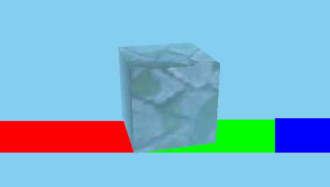
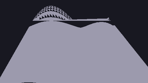
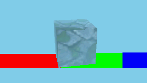
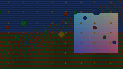
These frames come straight out of the Verilog RTL in simulation. There are more in sim/proof-of-concept/.
Two chips split the work.
The Lattice ECP5 (LFE5U-85F) runs the graphics engine: a 2D tile and sprite PPU (text and affine backgrounds, sprites, a scanline compositor), a perspective-correct textured 3D rasterizer, a 32-bit SDRAM subsystem, and RGB panel scanout. All of it is custom Verilog.
The STM32H723 runs game logic, audio, input, and 3D geometry, streaming screen-space work to the FPGA over a parallel bus.
The 3D core is built on RasterIX (see Credits) and extended into a gaming-oriented hybrid GPU that sits next to the 2D engine and compositor.
Everything below is sim and synth validated:
| Path | Contents |
|---|---|
| rtl/ | All the Verilog: 2D PPU, 3D integration, SDRAM controller and clock crossing, FMC bridge, scanout, clocking, board top. |
| hardware/ | KiCad project for the 6-layer board: ECP5, STM32H723, SDRAM, panel, power, audio, controls. |
| build/ | Bitstream build notes and the reproduce recipe. |
| sim/ | Verilator testbenches for every RTL block plus a headless 3D harness. Rendered frames are in sim/proof-of-concept/. |
No vendor tools:
yosys <synth script>            # produces gpuchip_ecp5.json
nextpnr-ecp5 --85k --package CABGA381 --speed 8 \
  --json gpuchip_ecp5.json --lpf rtl/gpu_chip.lpf --seed 4 \
  --textcfg gpuchip.config
ecppack gpuchip.config gpuchip.bit
The RTL depends on the RasterIX 3D core (submodule linked). Clone with submodules to include it:
git clone --recursive <repo-url>
# or, in an existing clone:
git submodule update --init --recursive
The full build and flashing steps are in build/README.md.
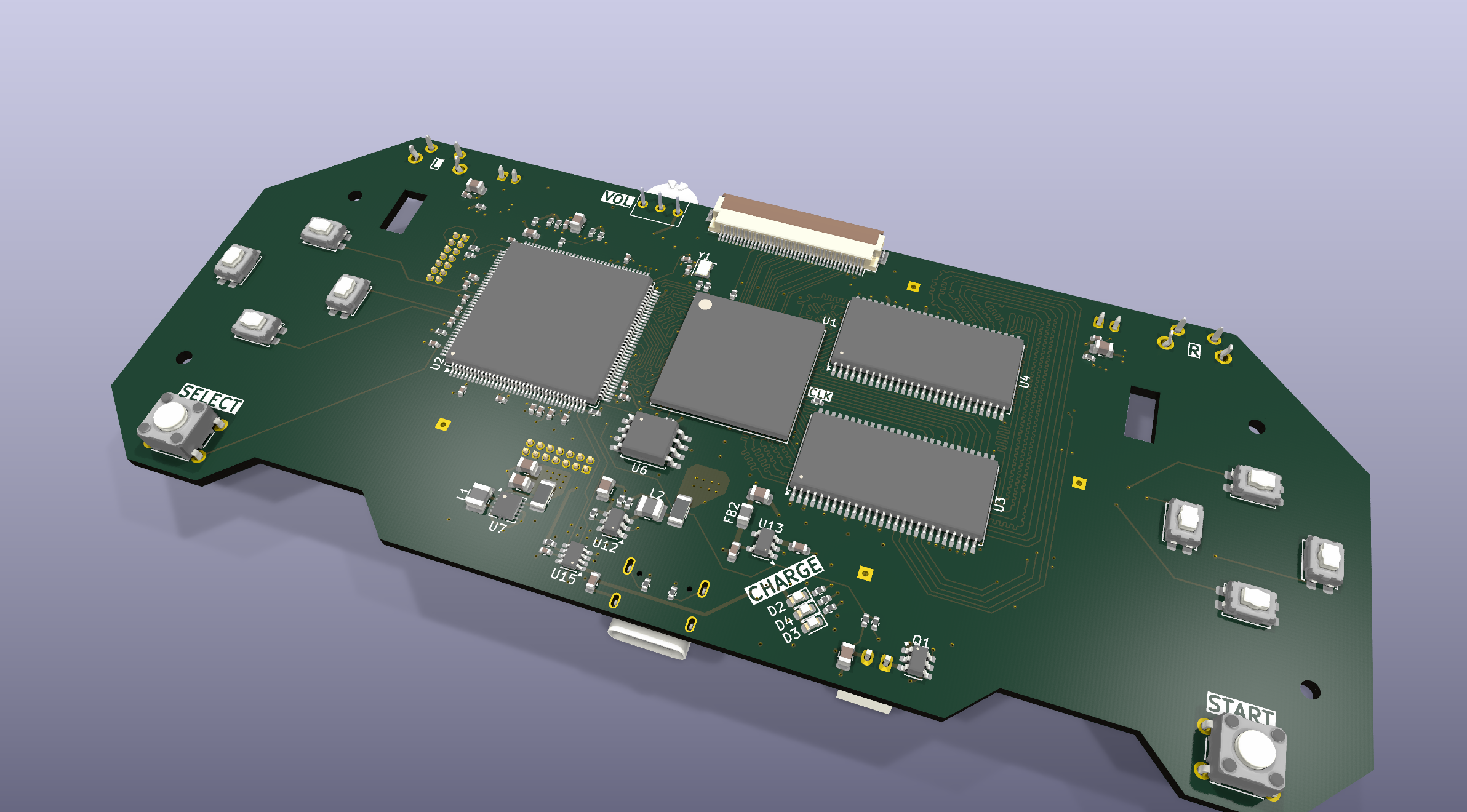
A 6-layer board in KiCad: the ECP5-85 FPGA and STM32H723 MCU, 32-bit SDRAM, a 4.3 inch 480x272 RGB panel with a boost-driven backlight, microSD, USB-C charging, stereo audio, and tactile controls. Schematics, layout, and 3D renders are under hardware/.
v0.1 is done and two boards are being made, firmware's likely the next step.
Everything in the repo reflects the design as sent for manufacture. All RTL validated, waiting on physical boards.
The 3D rasterizer is built on RasterIX by ToNi3141, an open-source fixed-function OpenGL-ES rasterizer (GPL-3.0). This project extends it into a hybrid 2D and 3D console GPU. Big thanks to that work.
The repository is dual-licensed by directory:
See LICENSING.md for the breakdown and the per-file SPDX tags.
| Qty | Value | Footprint | References |
|---|---|---|---|
| 75 | 100nF | Capacitor_SMD:C_0402_1005Metric | C10, C11, C12, C100, C105, C108, C110, C113, C114, C115, C116, C117, C118, C121, C122, C123 +59 |
| 23 | 10uF | Capacitor_SMD:C_0805_2012Metric | C1, C3, C4, C5, C19, C24, C27, C44, C51, C103, C107, C111, C112, C119, C120, C130 +7 |
| 12 | 10k | Resistor_SMD:R_0402_1005Metric | R16, R19, R20, R21, R22, R33, R34, R35, R36, R42, R43, R57 |
| 10 | 100nF | Capacitor_SMD:C_0201_0603Metric | C85, C89, C93, C94, C96, C98, C101, C104, C106, C109 |
| 8 | 22 | Resistor_SMD:R_0402_1005Metric | R23, R24, R25, R26, R27, R28, R44, R56 |
| 7 | TestPoint | TestPoint:TestPoint_Pad_1.5x1.5mm | TP1, TP3, TP4, TP5, TP7, TP8, TP9 |
| 6 | 22uF | Capacitor_SMD:C_0805_2012Metric | C25, C26, C46, C87, C91, C95 |
| 6 | 47k | Resistor_SMD:R_0402_1005Metric | R10, R45, R46, R47, R48, R49 |
| 5 | 100k | Resistor_SMD:R_0402_1005Metric | R11, R12, R13, R15, R53 |
| 4 | 4.7k | Resistor_SMD:R_0402_1005Metric | R30, R31, R32, R40 |
| 4 | TestPoint | TestPoint:TestPoint_THTPad_1.5x1.5mm_Drill0.7mm | TP10, TP11, TP12, TP13 |
| 3 | 1k | Resistor_SMD:R_0402_1005Metric | R4, R9, R41 |
| 3 | 1uF | Capacitor_SMD:C_0603_1608Metric | C21, C28, C48 |
| 3 | 2.2uF | Capacitor_SMD:C_0603_1608Metric | C29, C49, C50 |
| 3 | 33 | Resistor_SMD:R_0402_1005Metric | R29, R38, R55 |
| 3 | 470 | Resistor_SMD:R_0402_1005Metric | R5, R6, R7 |
| 3 | LED | LED_SMD:LED_0603_1608Metric | D2, D3, D4 |
| 2 | 0 | Resistor_SMD:R_1206_3216Metric | R50, R51 |
| 2 | 2k | Resistor_SMD:R_0402_1005Metric | R3, R8 |
| 2 | 49.9 | Resistor_SMD:R_0402_1005Metric | R17, R18 |
| 2 | 5.1k | Resistor_SMD:R_0402_1005Metric | R1, R2 |
| 2 | AS4C4M16SA | Package_SO:TSOP-II-54_22.2x10.16mm_P0.8mm | U3, U4 |
| 2 | Conn_ST_STDC14 | Connector_PinHeader_1.27mm:PinHeader_2x07_P1.27mm_Vertical | J5, J6 |
| 2 | MAX98357A | Package_DFN_QFN:TQFN-16-1EP_3x3mm_P0.5mm_EP1.23x1.23mm | U8, U17 |
| 2 | Speaker 4-8 ohm | Connector_TE-Connectivity:TE_440054-2_1x02_P2.00mm_Vertical | LS1, LS2 |
| 1 | 0.47uF | Capacitor_SMD:C_0402_1005Metric | C22 |
| 1 | 0.5mm FPC Conn | Connector_FFC-FPC:Hirose_FH12-40S-0.5SH_1x40-1MP_P0.50mm_Horizontal | J4 |
| 1 | 1.5uH | Inductor_SMD:L_1008_2520Metric | L1 |
| 1 | 10 | Resistor_SMD:R_0402_1005Metric | R37 |
| 1 | 10k Linear | Potentiometer_THT:Potentiometer_Bourns_3266Y_Vertical | RV1 |
| 1 | 10nF | Capacitor_SMD:C_0402_1005Metric | C73 |
| 1 | 10uH | Inductor_SMD:L_Abracon_ASPI-4030S | L3 |
| 1 | 120@100MHz | Inductor_SMD:L_0805_2012Metric | FB2 |
| 1 | 120k | Resistor_SMD:R_0402_1005Metric | R14 |
| 1 | 1S LiPo | Connector_JST:JST_PH_B2B-PH-K_1x02_P2.00mm_Vertical | J3 |
| 1 | 1uF | Capacitor_SMD:C_1206_3216Metric | C127 |
| 1 | 2.2uH | Inductor_SMD:L_1008_2520Metric | L2 |
| 1 | 220k | Resistor_SMD:R_0402_1005Metric | R54 |
| 1 | 220nF | Capacitor_SMD:C_0402_1005Metric | C128 |
| 1 | 240k | Resistor_SMD:R_0402_1005Metric | R39 |
| 1 | 2N7002 | Package_TO_SOT_SMD:SOT-23 | Q3 |
| 1 | 4.7uF | Capacitor_SMD:C_0603_1608Metric | C30 |
| 1 | 47nF | Capacitor_SMD:C_0402_1005Metric | C23 |
| 1 | 600@100MHz | Inductor_SMD:L_0805_2012Metric | FB1 |
| 1 | A | Button_Switch_SMD:SW_SPST_EVQP2_ShortPushTravel_H2.5mm | SW7 |
| 1 | AO3401A | Package_TO_SOT_SMD:SOT-23 | Q2 |
| 1 | AP2112K-2.5 | Package_TO_SOT_SMD:SOT-23-5 | U13 |
| 1 | APS6404L-3SQRx-SN | Package_SO:SOIC-8_3.9x4.9mm_P1.27mm | U16 |
| 1 | B | Button_Switch_SMD:SW_SPST_EVQP2_ShortPushTravel_H2.5mm | SW8 |
| 1 | DW01A | Package_TO_SOT_SMD:SOT-23-6 | U10 |
| 1 | D_DOWN | Button_Switch_SMD:SW_SPST_EVQP2_ShortPushTravel_H2.5mm | SW2 |
| 1 | D_LEFT | Button_Switch_SMD:SW_SPST_EVQP2_ShortPushTravel_H2.5mm | SW3 |
| 1 | D_RIGHT | Button_Switch_SMD:SW_SPST_EVQP2_ShortPushTravel_H2.5mm | SW4 |
| 1 | D_UP | Button_Switch_SMD:SW_SPST_EVQP2_ShortPushTravel_H2.5mm | SW1 |
| 1 | FORCE_RECON | Button_Switch_SMD:SW_Push_SPST_NO_Alps_SKRK | SW14 |
| 1 | FS8205 | Package_TO_SOT_SMD:SOT-23-6 | Q1 |
| 1 | L | Button_Switch_THT:SW_Tactile_SPST_Angled_PTS645Vx39-2LFS | SW5 |
| 1 | LFE5U-85F-8BG381x | Package_BGA:Lattice_caBGA-381_17x17mm_Layout20x20_P0.8mm | U1 |
| 1 | LOGO | sonic-rush-handheld:logo | G*** |
| 1 | LTC2954CTS8-1-TRPBF | Package_TO_SOT_SMD:TSOT-23-8 | U15 |
| 1 | MAIN | Button_Switch_SMD:SW_SPST_SKQG_WithStem | SW13 |
| 1 | MCP73871 | Package_DFN_QFN:QFN-20-1EP_4x4mm_P0.5mm_EP2.5x2.5mm | U11 |
| 1 | Micro_SD_Card_Det1 | Connector_Card:microSD_HC_Hirose_DM3D-SF | J1 |
| 1 | NTC 10k | Resistor_SMD:R_0603_1608Metric | TH1 |
| 1 | R | Button_Switch_THT:SW_Tactile_SPST_Angled_PTS645Vx39-2LFS | SW6 |
| 1 | SEL | Button_Switch_THT:SW_TH_Tactile_Omron_B3F-100x | SW12 |
| 1 | SMAJ5.0A | Diode_SMD:D_SMA | D1 |
| 1 | SS16 | Diode_SMD:D_SMA | D5 |
| 1 | START | Button_Switch_THT:SW_TH_Tactile_Omron_B3F-100x | SW11 |
| 1 | STM32H723ZGTx | Package_QFP:LQFP-144_20x20mm_P0.5mm | U2 |
| 1 | SW_Push | Button_Switch_SMD:SW_Push_SPST_NO_Alps_SKRK | SW15 |
| 1 | SiT8008xx-7x-xxE | Oscillator:Oscillator_SMD_SiT_PQFN-4Pin_2.0x1.6mm | Y1 |
| 1 | TLV62569DDC | Package_TO_SOT_SMD:SOT-23-6 | U12 |
| 1 | TPS61165DBV | Package_TO_SOT_SMD:SOT-23-6 | U14 |
| 1 | TPS63001 | Package_SON:Texas_DRC0010J_ThermalVias | U7 |
| 1 | USB_C_Receptacle_USB2.0_16P | Connector_USB:USB_C_Receptacle_G-Switch_GT-USB-7010ASV | J2 |
| 1 | W25Q32JVSS | Package_SO:SOIC-8_5.3x5.3mm_P1.27mm | U6 |
| 1 | X | Button_Switch_SMD:SW_SPST_EVQP2_ShortPushTravel_H2.5mm | SW9 |
| 1 | Y | Button_Switch_SMD:SW_SPST_EVQP2_ShortPushTravel_H2.5mm | SW10 |

Rishabh416/microbot
My first fully custom project inspired by the microbots from the movie Big Hero 6. My goal is to get into swarm robotics and I believe this is a HUGE leap in that direction, but a good moment to learn.

Badbird5907/thermal-camera
My design of a cheap and affordable thermal camera


MangoIV/le_chiff_ble
A drop-in replacement-PCB for the beautiful le_chiffre

KaliAssistant/Fox-Jack
Portable social-engineering LAN tool for automated payloads and wired audits — based on Luckfox Pico Max

It measures 146.1 × 58.4 mm and has 6 copper layers, 1.6 mm thick.
248 parts, built around the MCP73871EV, TPS61165DBV, TPS63001DRC and W25Q32JVSSIQ. The full list of its parts is on this page, with links to each part's symbol and footprint where PCBKit's library has them.
From the badaboombox/SS-Handheld-Console repository on GitHub, at the commit this page was made from: the board is hardware/Comp Board/Comp Board.kicad_pcb and its schematic hardware/Comp Board/Audio.kicad_sch. PCBKit opens the board in the browser, with nothing to install.
Its repository states no licence, so its author keeps all rights: ask badaboombox before reusing the design.