4 layers49.4 × 111.4 mm
Eeg hardware v1
es-ude/eeg-hardware
Repo of the Custom Hardware Design Files of the EEG-based Gaming Controller
412 partsMIT
 amonbenson/expad
A four-jack USB MIDI adapter for expression and sustain pedals, built on a Raspberry Pi Pico 2 W. It works out what is plugged into each jack - whichever contact a pedal's wiper is on, and whether it is a potentiometer…
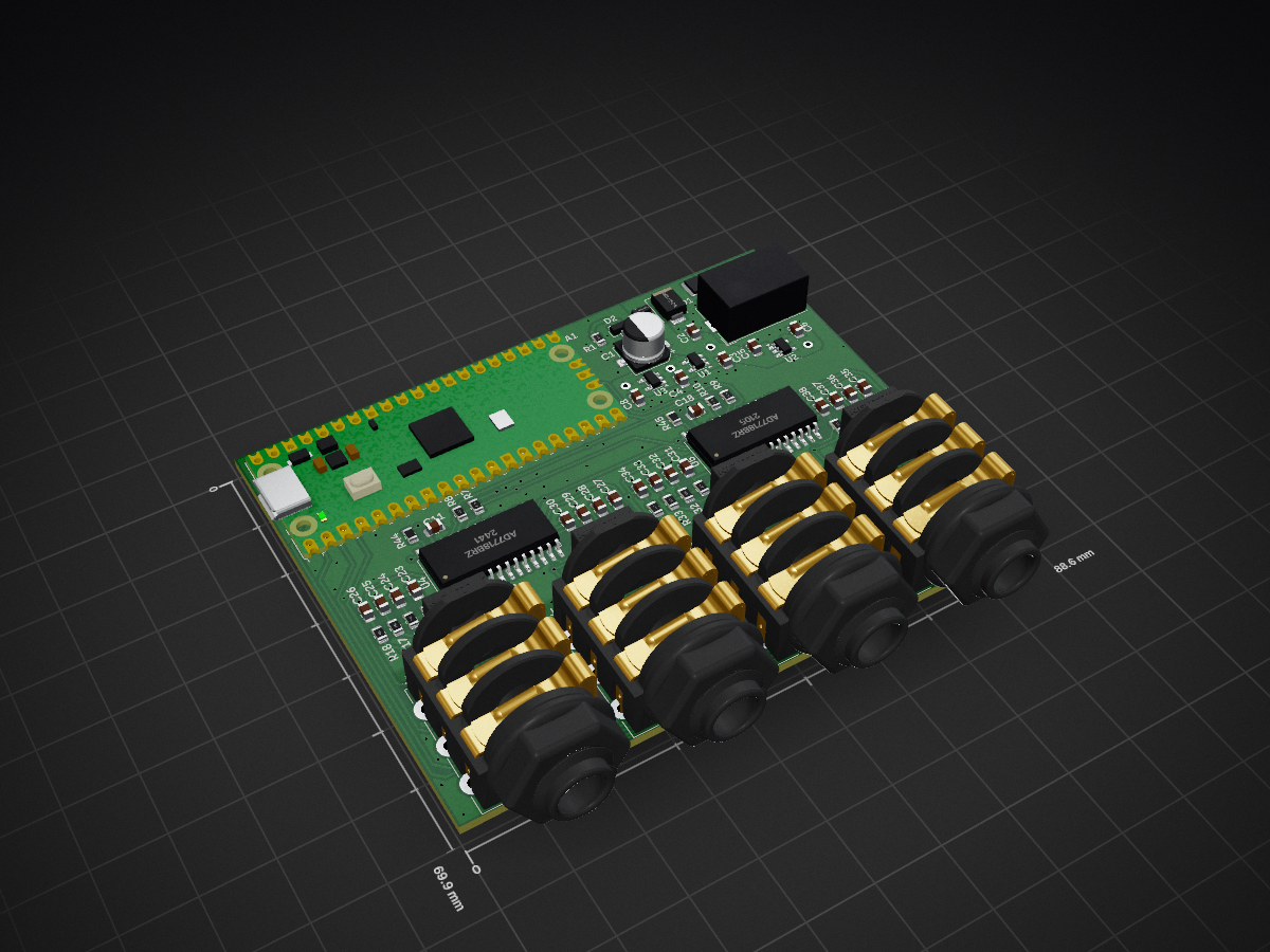
ExpressionController is an open-source printed circuit board by amonbenson, from the amonbenson/expad repository on GitHub, published under the MIT licence. It is a 2-layer board of 88.6 × 69.9 mm with 147 parts on 158 nets, routed with 1,136 tracks and 299 vias.
It is built around the 74AHCT1G125SE, AD7718BRZ and 74HC595DRG, with the ADP7142AUJZ-2.5-R7, ADP7142AUJZ-3.3-R7 and ADP7142AUJZ-5.0-R7 among its other parts. Its parts include 53 capacitors, 41 resistors, 18 ICs, 7 diodes and 5 connectors. It belongs with the RP2040 boards of this library.


A four-jack USB MIDI adapter for expression and sustain pedals, built on a Raspberry Pi Pico 2 W. It works out what is plugged into each jack - whichever contact a pedal's wiper is on, and whether it is a potentiometer, a switch or a two-wire rheostat - and sends every pedal's position as a MIDI control change, ~190 times per second. A WiFi access point serves a web interface for watching the jacks and changing the settings live.
The PCB is the KiCad project in hardware/. Each jack's tip, ring and sleeve (plus the tip's switch contact, for plug detection) can be switched to a shared 1 kΩ pull-up to the 2.5 V reference or a 1 kΩ pull-down, and is read back by one of two AD7718 24-bit ADCs. The four WS2812B LEDs below the jacks glow a dim white while a plug is in but no known pedal is behind it. A recognised pedal is announced for a second in its own color - purple for an expression pedal, lime for a footswitch, yellow for a rheostat - after which the LED shows the value it sends, from dark red at 0 through red, orange and yellow to white at 127. They run off a linear regulator, so the firmware caps them at ~4% brightness.
| Pedal | Cable | Shown as | Value |
|---|---|---|---|
| Expression pedal (potentiometer), wiper on tip or ring | stereo (TRS) | Tracking | wiper position, counting up away from the sleeve |
| Sustain pedal / footswitch | mono (TS) or stereo | Switch | 100% closed, 0% open |
| Two-wire (rheostat) expression pedal | mono or stereo | Rheostat | resistance against the nearest standard value (10k, 25k, 50k ...) |
| Anything else (dual footswitches, other wirings) | Other pedal | none |
Pedals are recognised within ~0.1 s of being plugged in, and unplugging is noticed just as fast.
The topology panel on the right draws the selected jack's measured network.
Needs Rust, Node.js (see engines in web/package.json) for the web interface,
and a debug probe (e.g. a Raspberry Pi Debug Probe) on the Pico's SWD pins.
rustup target add thumbv8m.main-none-eabihf
cargo install probe-rs-tools --locked
cp .env.example .env # then set EXPAD_WIFI_PASSWORD (8-63 characters)cargo run --bin expression_controller # build, flash and show the log
cargo run --bin expression_controller --features no-wifi # the same with the radio off
cargo build --no-default-features # without the web interface (no Node.js needed)The other programs in src/bin/ test parts of the board:
| Program | What it does |
|---|---|
detect_pin_mapping | checks every contact's switches and ADC input against the wiring table (unplug all jacks) |
capture | holds every contact in one state and logs every ADC input, for noise measurements |
adc_characterization | compares ADC filter rates and SPI settings on a pedal in jack 1 |
potentiometer | reads a pedal in jack 1 and shows its position on the LEDs |
rainbow | LED strip test |
midi_loopback | echoes every USB MIDI message back to the host |
web_interface | the web interface with made-up data |
cargo test -p expad-topology --target x86_64-pc-windows-msvc   # solver tests, on your host triple
cargo fmt
cargo clippy --all-features
cd web && npm run dev:mock   # web interface against a simulated device, no hardware needed
AGENTS.md describes the repository in detail, and docs/fast-tracking.md the measurements and design behind the pedal detection.
| Qty | Value | Footprint | References |
|---|---|---|---|
| 24 | 100n | Capacitor_SMD:C_0805_2012Metric | C11, C13, C16, C18, C20, C39, C40, C41, C42, C47, C48, C49, C50, C51, C52, C53 +8 |
| 17 | 10k | Resistor_SMD:R_0805_2012Metric | R15, R16, R17, R18, R23, R24, R25, R26, R31, R32, R33, R34, R39, R40, R41, R42 +1 |
| 16 | 10n | Capacitor_SMD:C_0805_2012Metric | C23, C24, C25, C26, C27, C28, C29, C30, C31, C32, C33, C34, C35, C36, C37, C38 |
| 15 | TestPoint | TestPoint:TestPoint_THTPad_D1.5mm_Drill0.7mm | TP1, TP2, TP3, TP4, TP5, TP6, TP7, TP8, TP9, TP10, TP11, TP12, TP13, TP14, TP15 |
| 12 | 47 | Resistor_SMD:R_0805_2012Metric | R3, R4, R5, R6, R7, R8, R9, R10, R46, R47, R48, R49 |
| 8 | 1k 0.1% | Resistor_SMD:R_0805_2012Metric | R50, R51, R52, R53, R54, R55, R56, R57 |
| 8 | TMUX1511PWR | Package_SO:TSSOP-14_4.4x5mm_P0.65mm | U15, U16, U17, U18, U19, U20, U21, U22 |
| 4 | 18p | Capacitor_SMD:C_0805_2012Metric | C14, C15, C21, C22 |
| 4 | 74HC595DR | Package_SO:SOIC-16_3.9x9.9mm_P1.27mm | U6, U8, U10, U12 |
| 4 | AudioJack | Jack_6.35mm_Neutrik_NMJ6HFD4_Horizontal:Jack_6.35mm_Neutrik_NMJ6HFD4_Horizontal | J2, J3, J4, J5 |
| 4 | WS2812B | LED_SMD:LED_WS2812B_PLCC4_5.0x5.0mm_P3.2mm | D4, D5, D6, D7 |
| 3 | 10u | Capacitor_SMD:C_0805_2012Metric | C2, C10, C17 |
| 3 | 2.2u | Capacitor_SMD:C_0805_2012Metric | C4, C6, C8 |
| 3 | SolderJumper_2_Open | Jumper:SolderJumper-2_P1.3mm_Open_RoundedPad1.0x1.5mm | JP1, JP2, JP3 |
| 2 | 0 | Resistor_SMD:R_0805_2012Metric | R44, R45 |
| 2 | 32.768kHz | MS1V-T1K:MS1V-T1K | Y1, Y2 |
| 2 | 4.7u | Capacitor_SMD:C_0805_2012Metric | C3, C5 |
| 2 | AD7718BRZ | Package_SO:SOIC-28W_7.5x17.9mm_P1.27mm | U4, U5 |
| 1 | 100k | Resistor_SMD:R_0805_2012Metric | R1 |
| 1 | 220 | Resistor_SMD:R_0805_2012Metric | R43 |
| 1 | 47u | Capacitor_SMD:CP_Elec_6.3x5.8 | C1 |
| 1 | 74AHCT1G125 | Package_TO_SOT_SMD:SOT-353_SC-70-5 | U14 |
| 1 | ADP7142AUJZ-2.5 | Package_TO_SOT_SMD:TSOT-23-5 | U3 |
| 1 | ADP7142AUJZ-3.3 | Package_TO_SOT_SMD:TSOT-23-5 | U1 |
| 1 | ADP7142AUJZ-5.0 | Package_TO_SOT_SMD:TSOT-23-5 | U2 |
| 1 | BZX84C15-7-F | Package_TO_SOT_SMD:SOT-23 | D2 |
| 1 | BarrelJack | Connector_BarrelJack:BarrelJack_CUI_PJ-102AH_Horizontal | J1 |
| 1 | DMP3099L-7 | Package_TO_SOT_SMD:SOT-23 | Q1 |
| 1 | MF-MSMF050-2 | Fuse:Fuse_1812_4532Metric | F1 |
| 1 | PMEG6010ELR | Diode_SMD:Nexperia_CFP3_SOD-123W | D3 |
| 1 | RaspberryPi_Pico | Pico_2W_with_Header:Pico_2W_with_Header | A1 |
| 1 | SMBJ15CA | Diode_SMD:D_SMB | D1 |
It measures 88.6 × 69.9 mm and has 2 copper layers, 1.58 mm thick.
147 parts, built around the 74AHCT1G125SE, AD7718BRZ, 74HC595DRG and ADP7142AUJZ-2.5-R7. The full list of its parts is on this page, with links to each part's symbol and footprint where PCBKit's library has them.
From the amonbenson/expad repository on GitHub, at the commit this page was made from: the board is hardware/ExpressionController.kicad_pcb and its schematic hardware/AnalogFrontend.kicad_sch. PCBKit opens the board in the browser, with nothing to install.
Its repository publishes it under the MIT licence: you may reuse it on that licence's terms (keep the author's notice, and for a copyleft licence share your changes alike).
es-ude/eeg-hardware
Repo of the Custom Hardware Design Files of the EEG-based Gaming Controller

blinken/power-rail-probe
Low-noise oscilloscope power rail probe

Ledger-Donjon/curmea
To analyze the power consumption of a component, it is common to measure the current going to the ground by placing a small resistor and measuring the voltage across it.


m888r/scr23-analog-to-can
USC Racing 2023 FSAE Car Analog/Digital to CAN module