4 layers40.3 × 68.8 mm

 RICCIARDI-Adrien/Cyclope5
Raspberry Pi powered robot with camera live stream and 360° lidar.
Cyclope is an open-source printed circuit board by RICCIARDI-Adrien, from the RICCIARDI-Adrien/Cyclope repository on GitHub, published under the MIT licence. It is a 2-layer board of 100 × 84 mm with 88 parts on 61 nets, routed with 317 tracks and 95 vias.
It is built around the MCP3002-I/P, TPS565208DDC and DMG3414U, with the DMG2301L, 1101M2S3ABE2 and IHLP3232DZER3R3M01 among its other parts. Its parts include 24 resistors, 23 capacitors, 7 transistors, 6 connectors and 4 diodes. It belongs with the robots and motor control and computers and single-board computers boards of this library.


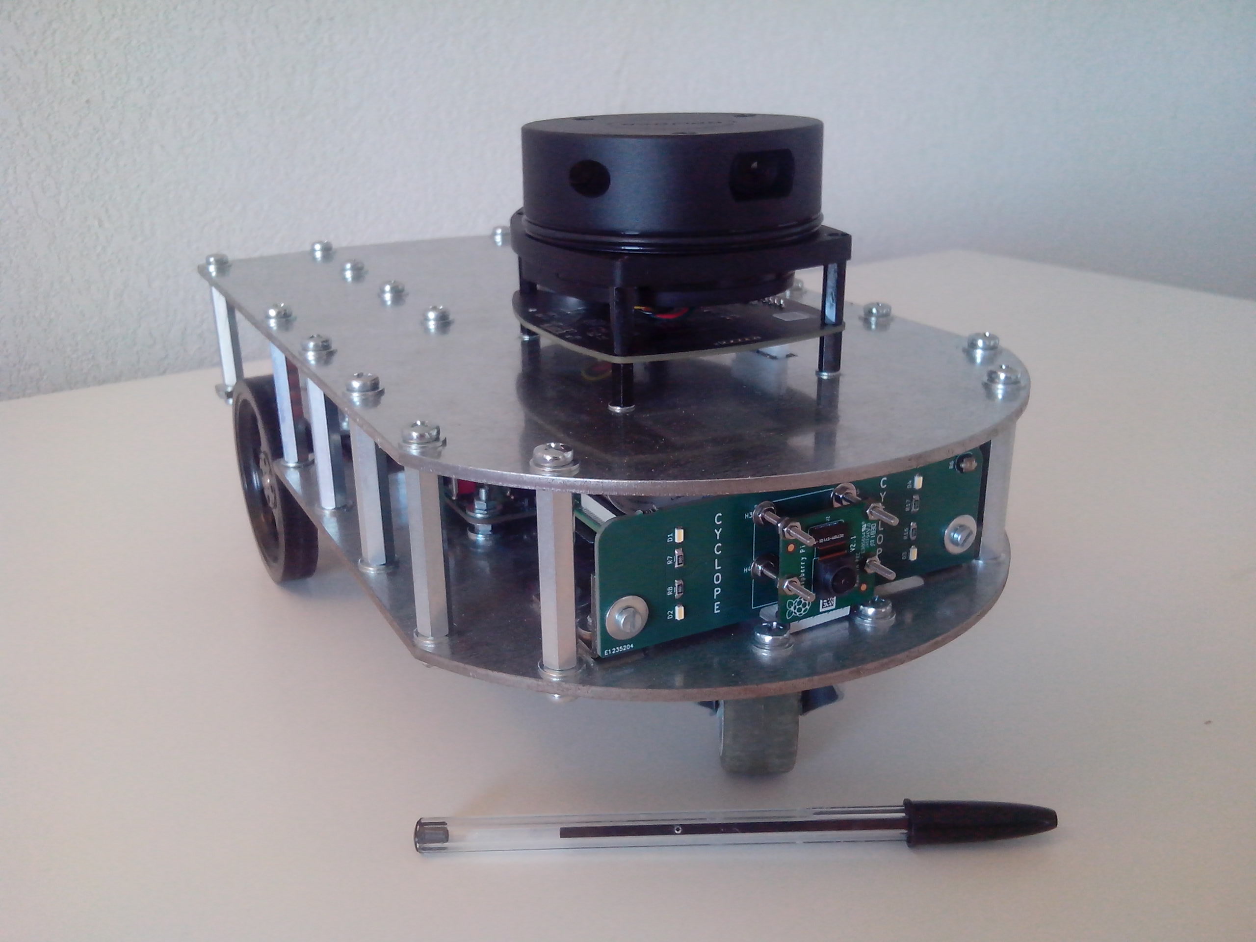
A little robot powered by a Raspberry Pi 3 A+, featuring a 8MPixel Raspberry Pi Camera V2 and a 360° lidar.
A fast WiFi connection allows to remote control the robot while displaying camera real-time full HD video stream.
A tailored Buildroot Linux distribution runs the software, controlled through WiFi through an embedded web server.
PCB has been designed using KiCad 5.1.5 and has been ported to KiCad 6. All manufacturing files are available from Release page.
A PDF version of the schematic is also provided.
Robot's Raspberry Pi is powered by a tailored Buildroot Linux distribution.
Clone the repository and the submodules all in the row :
git clone --recurse-submodules https://github.com/RICCIARDI-Adrien/CyclopeEnter repository directory, clean previous build (if needed) and generate image :
cd Cyclope/Software/buildroot
make distclean
make BR2_EXTERNAL=$(realpath ..)/cyclope cyclope_defconfig
make
Generated image to burn to a SD card is Cyclope/Software/buildroot/output/images/sdcard.img.
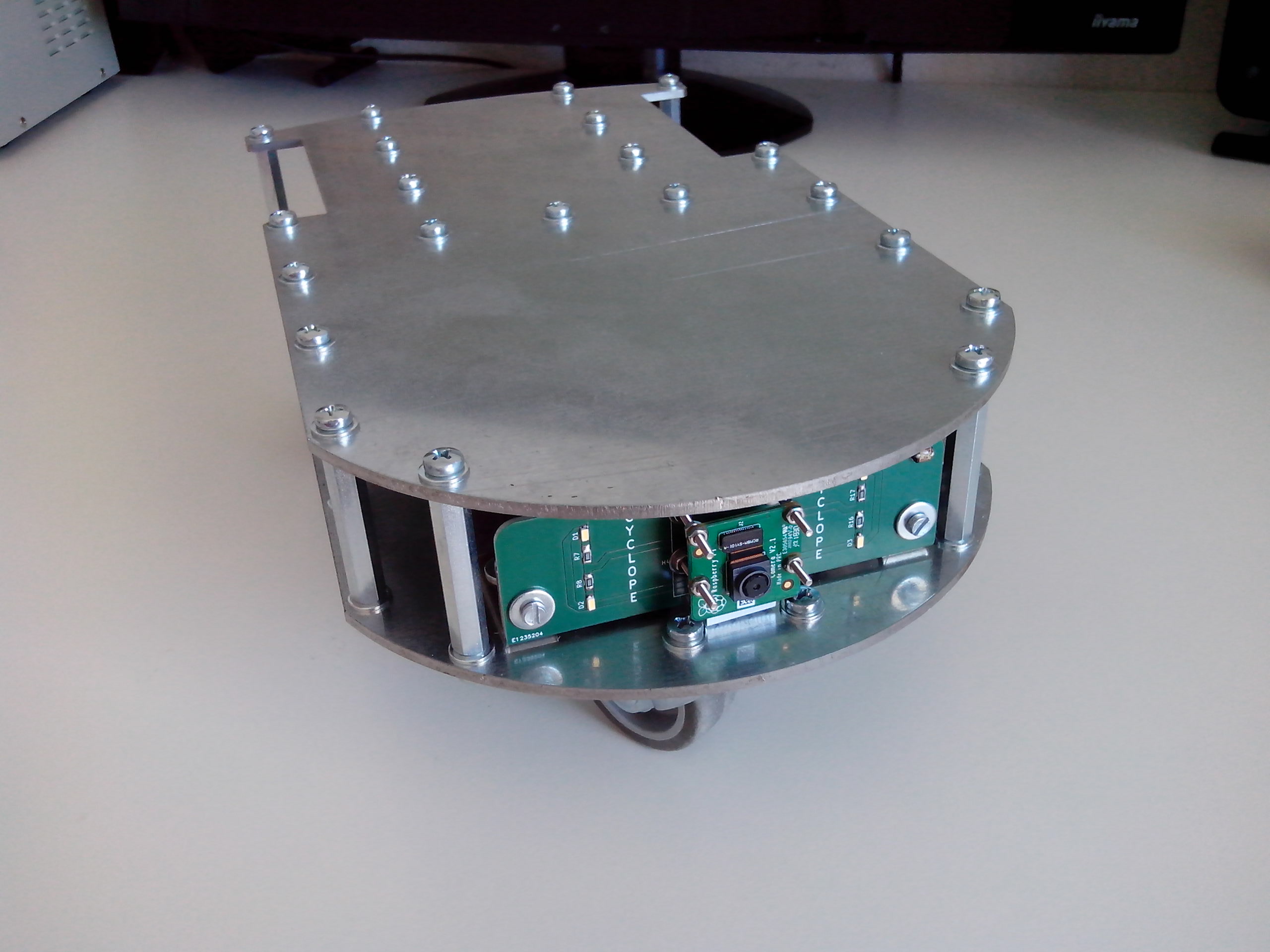
Chassis is made of two overlaid 3mm-thick steel plates.
See Mechanical_Dimensions.odg file for additional design information.
Provide the Chassis.dxf file from Release page to a metal laser cutting service.
See Bill_Of_Material.csv file from Release page for PCB parts. All other needed mechanical and electrical parts are listed below.
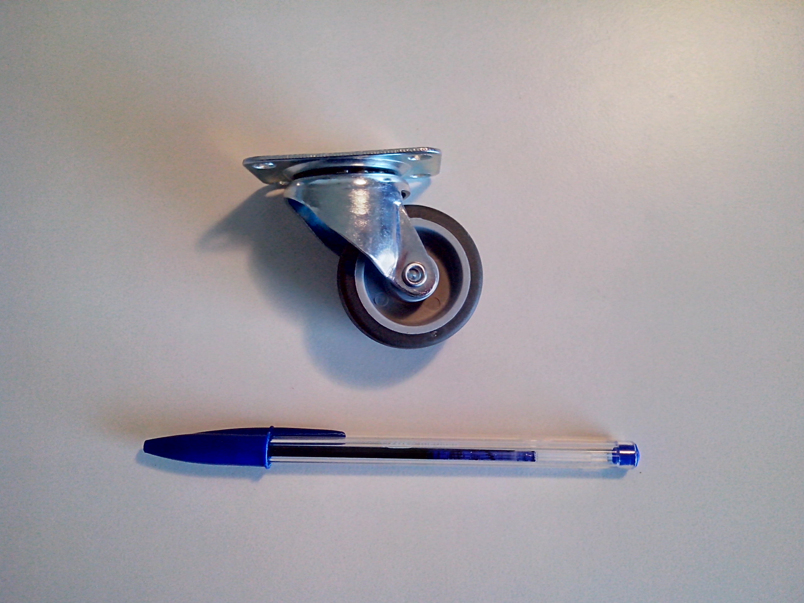
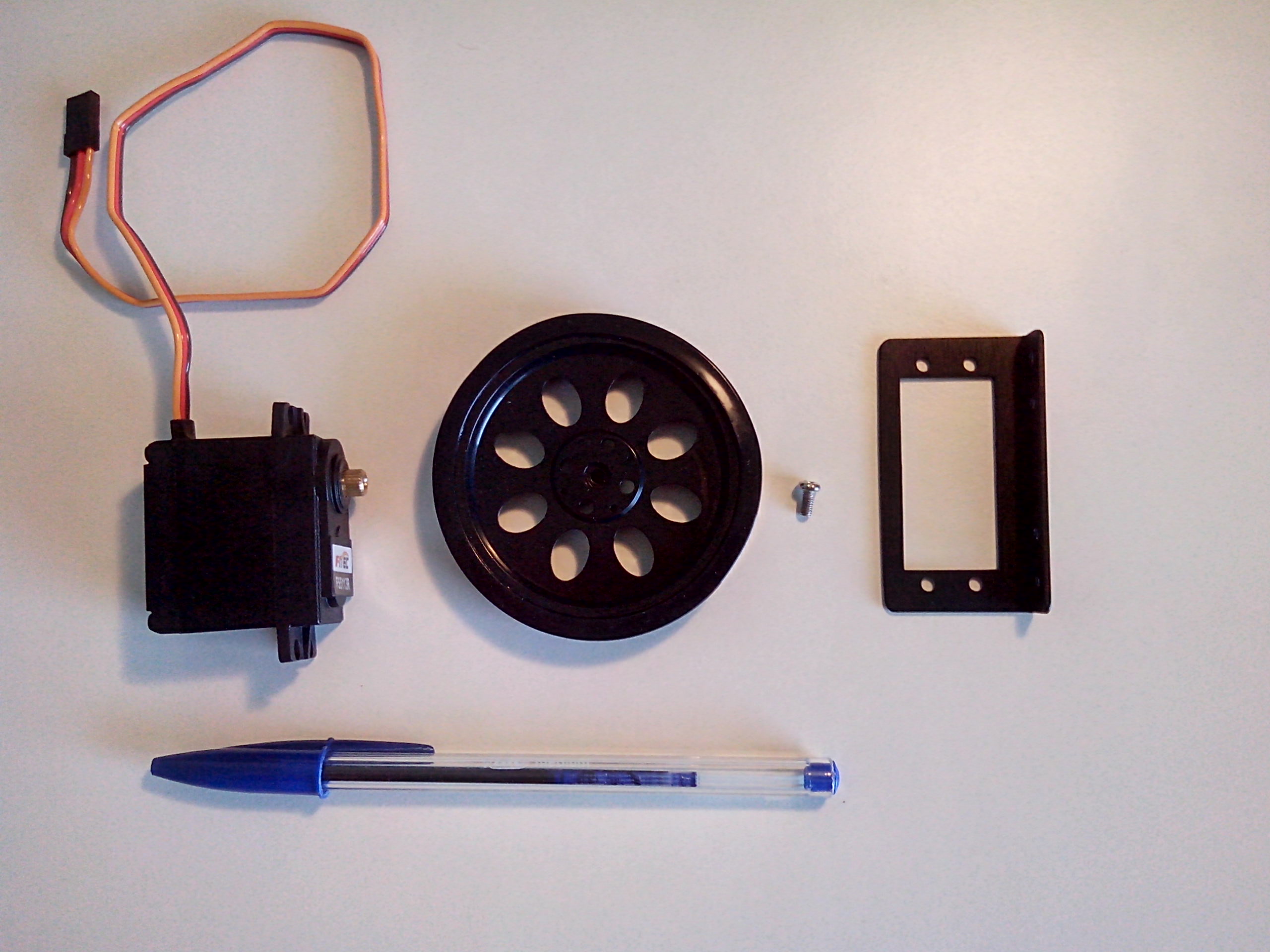
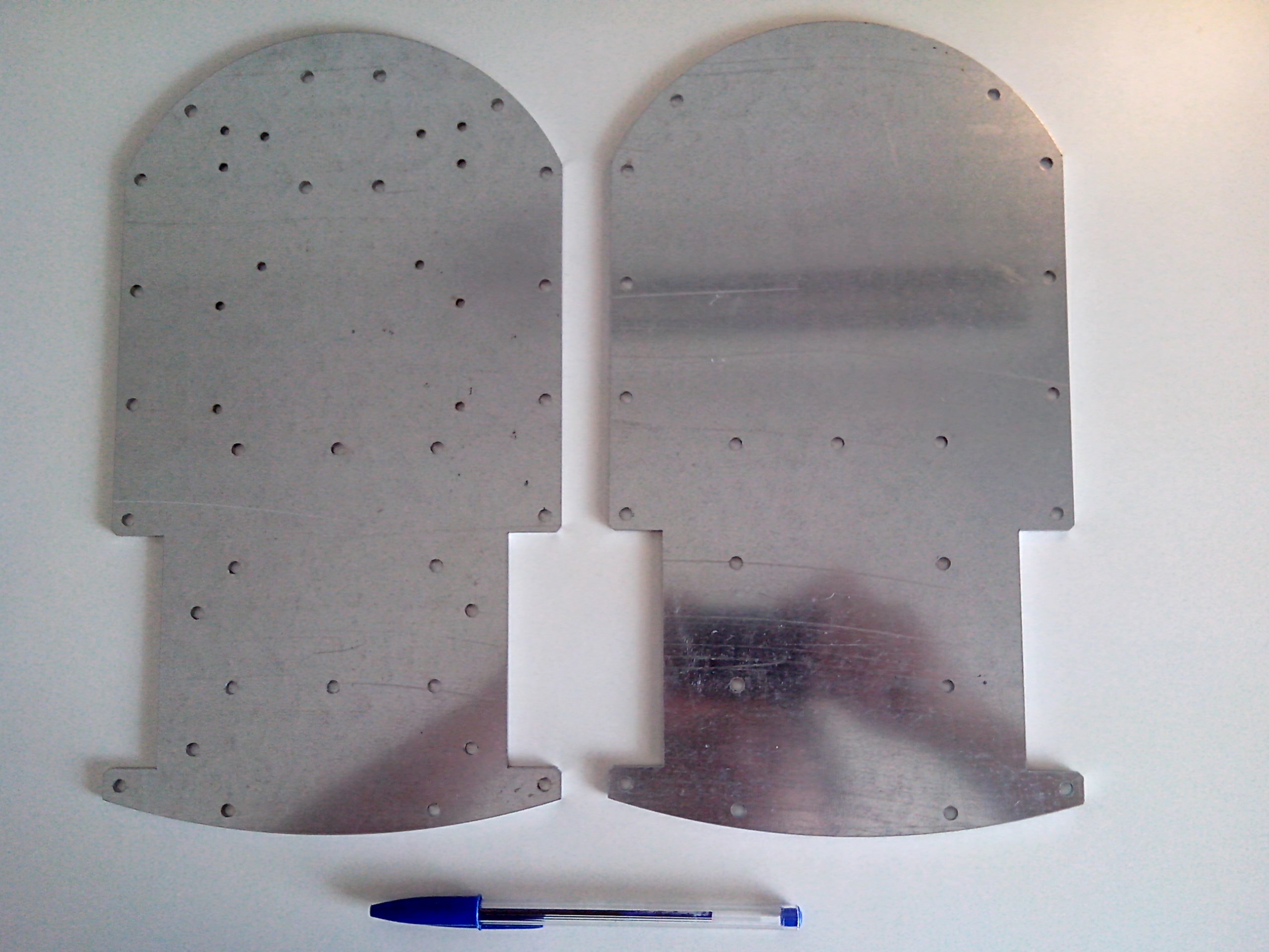
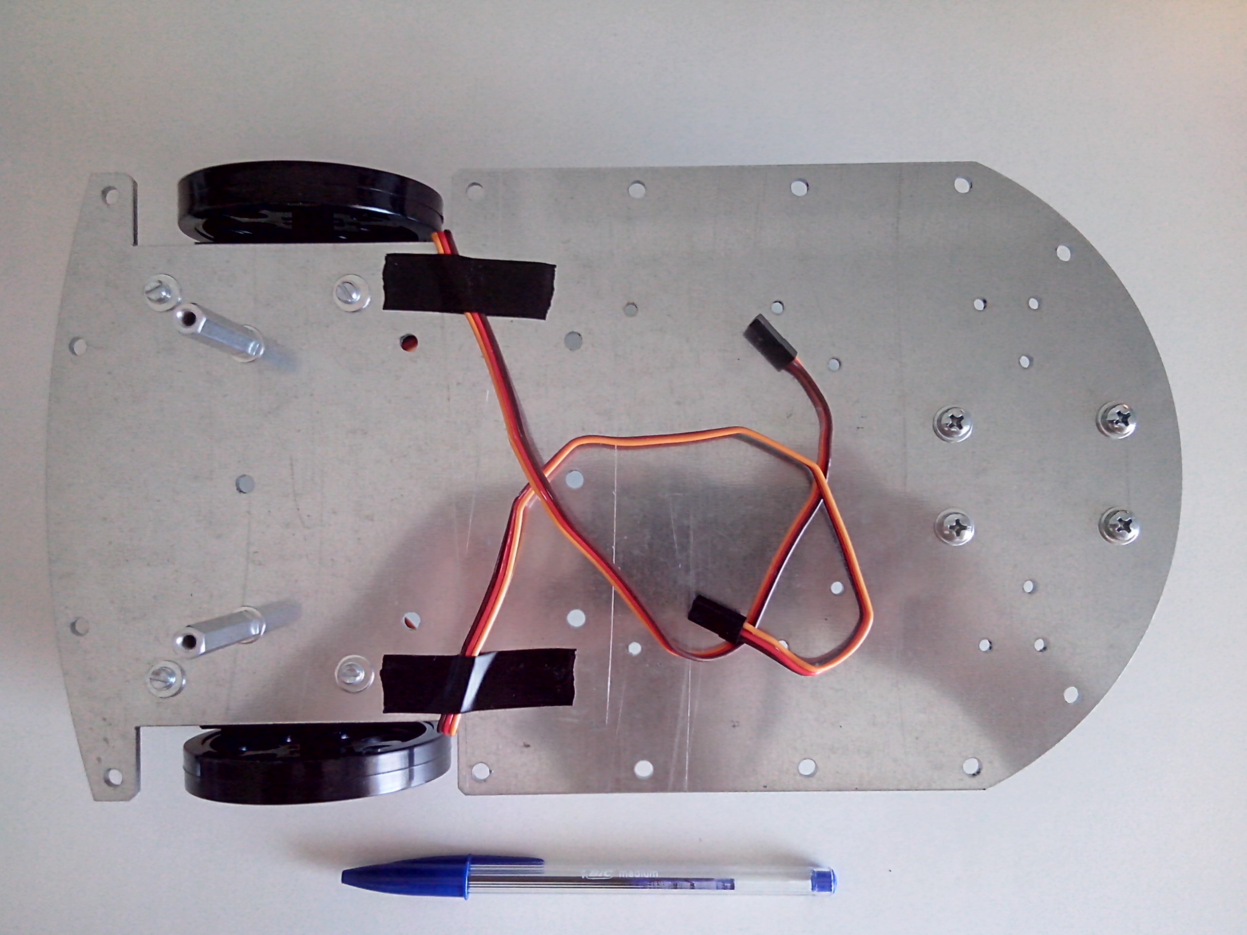
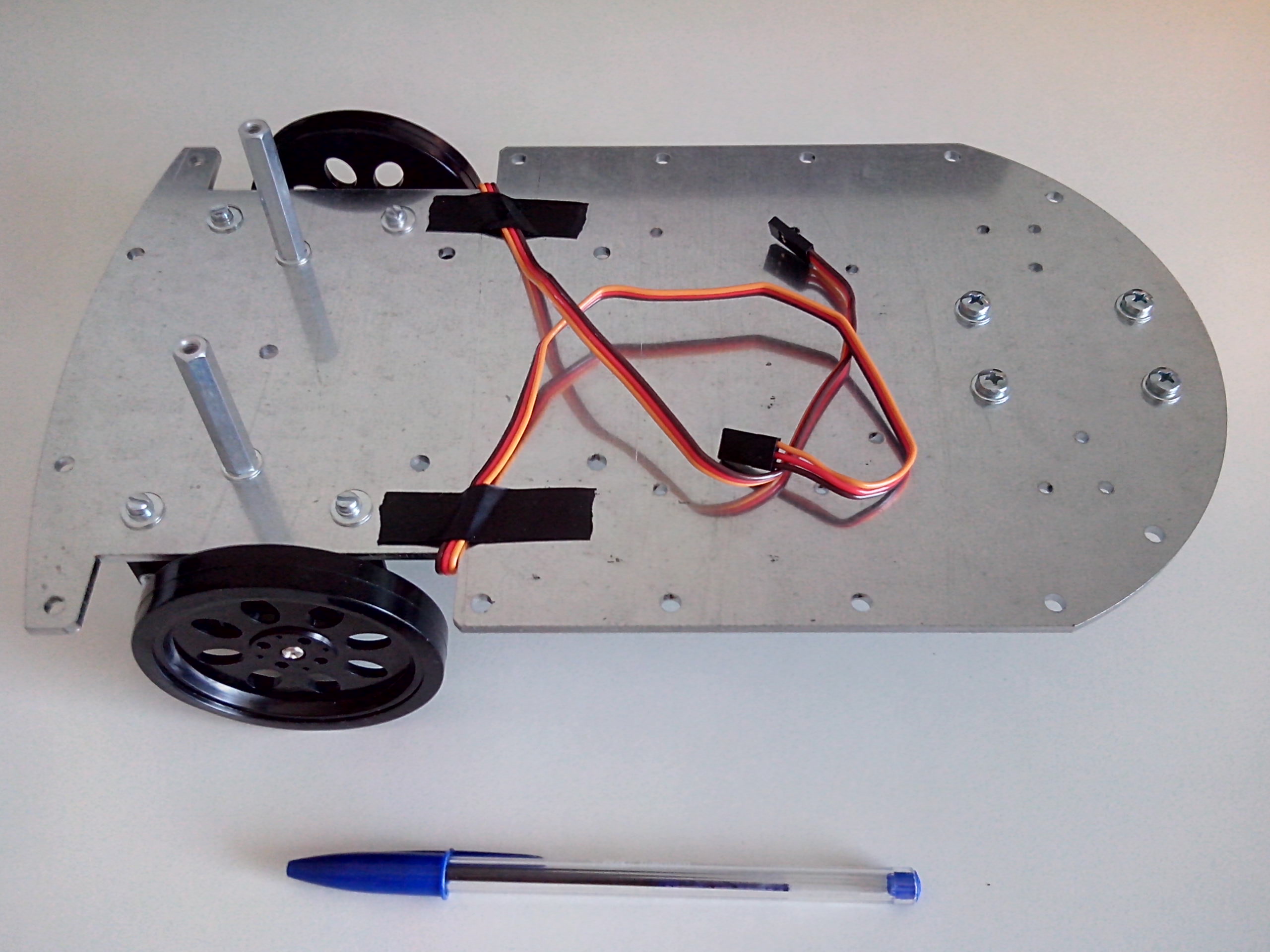
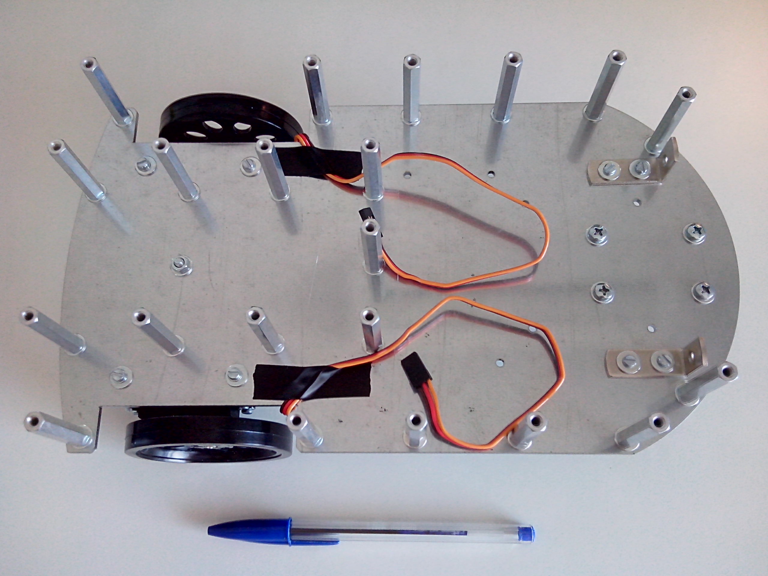
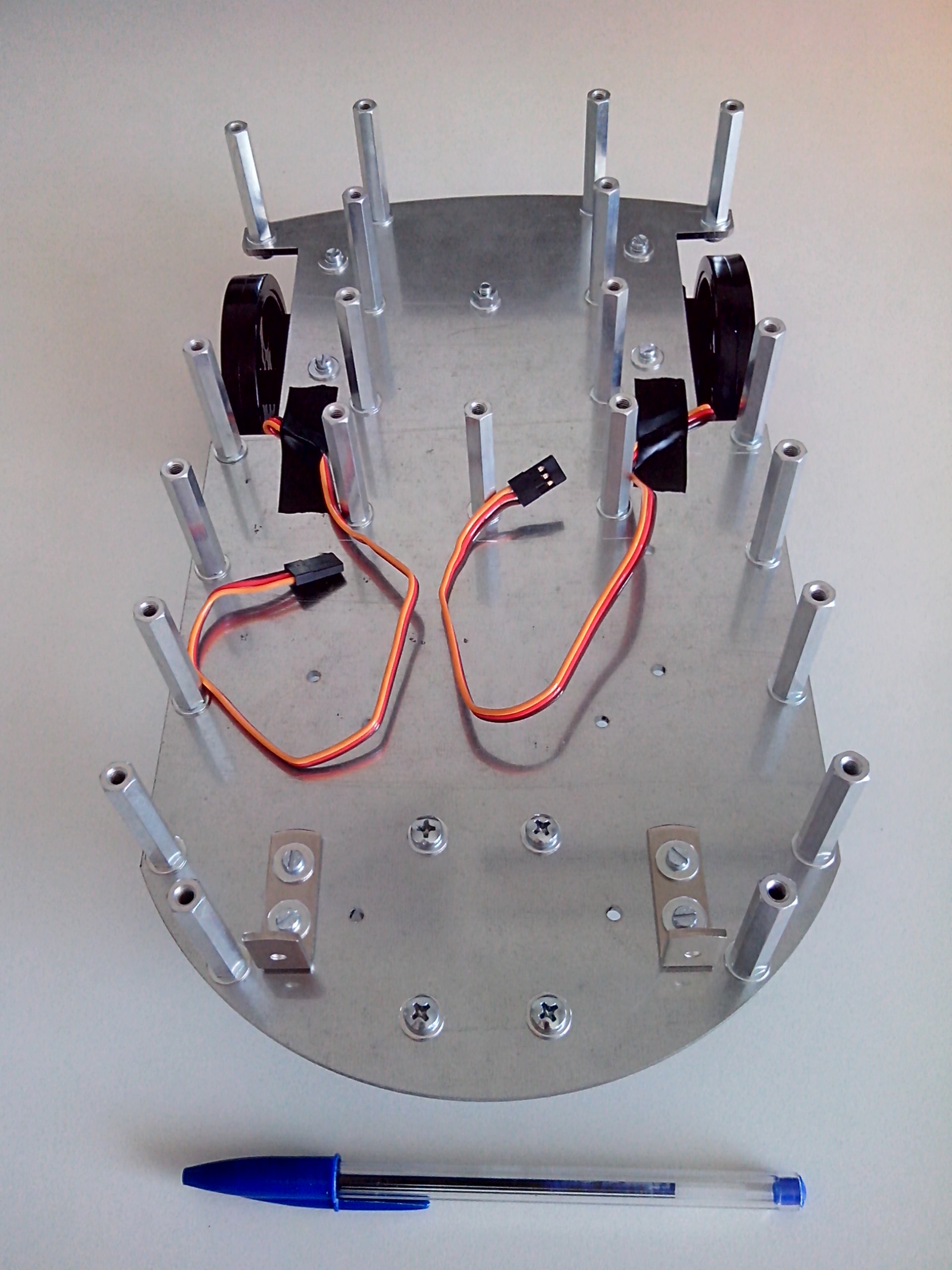
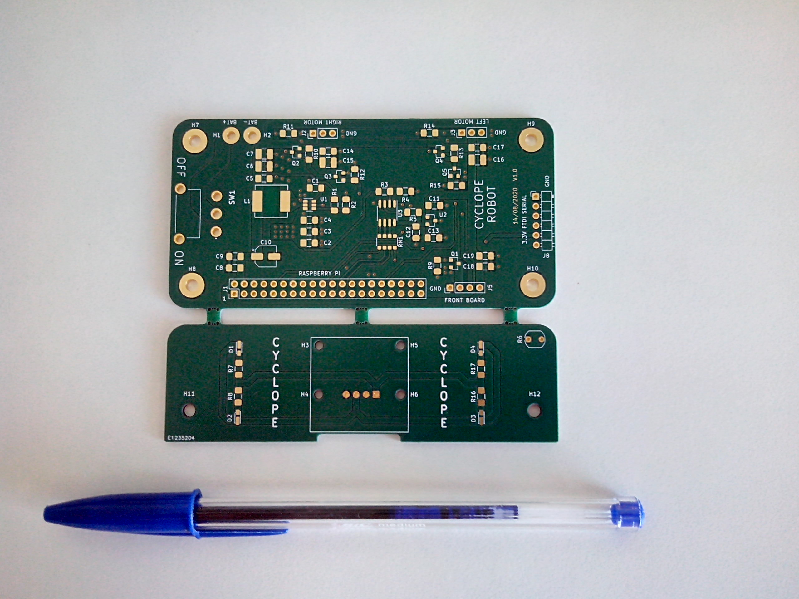
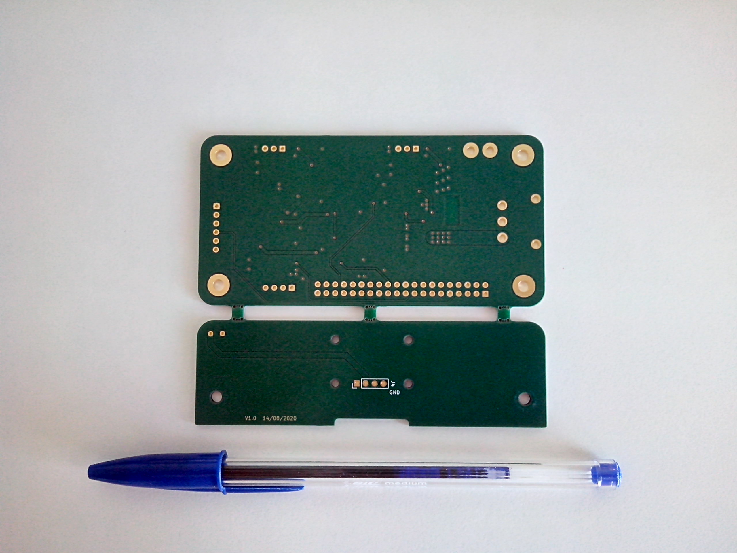
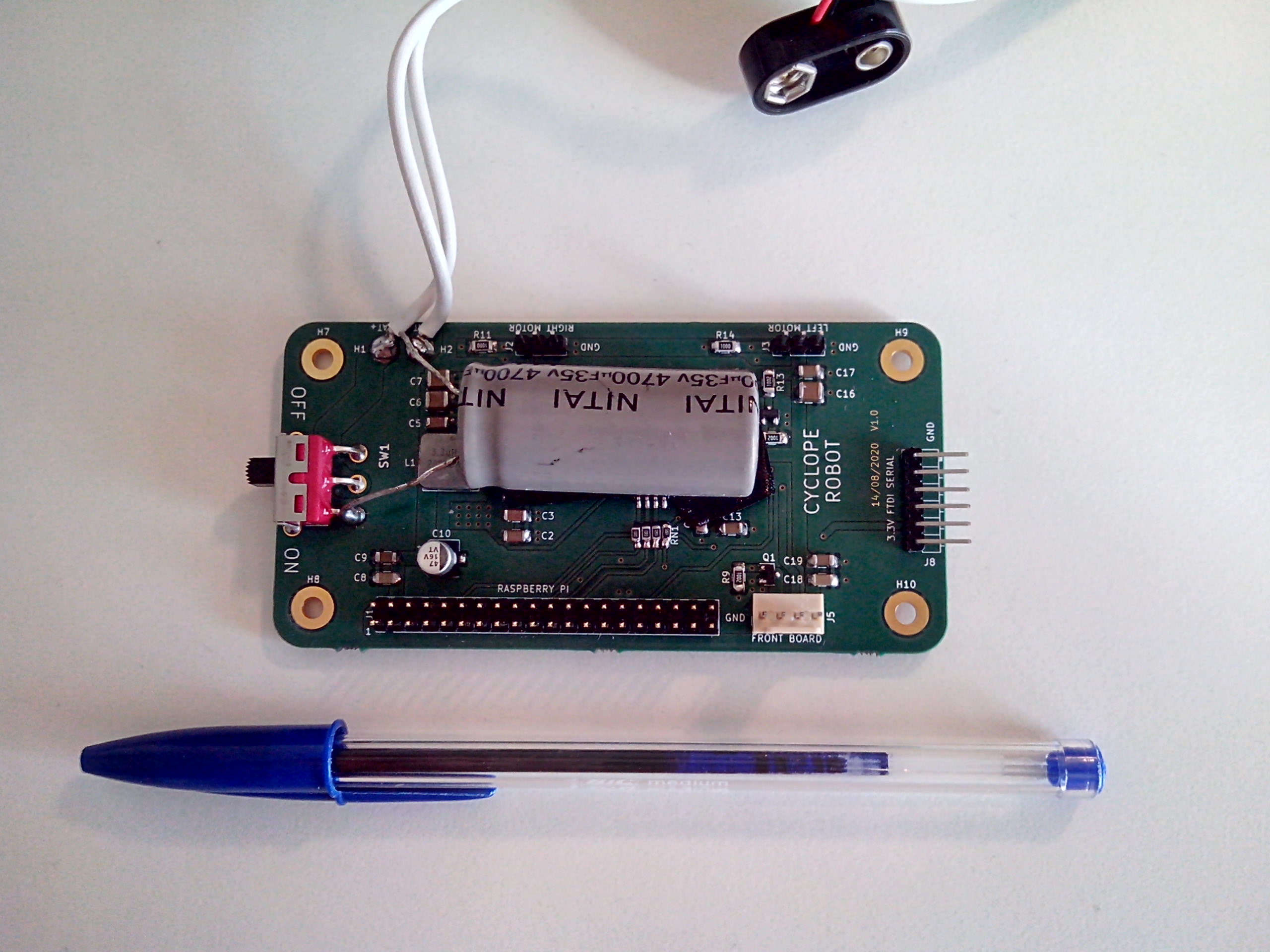
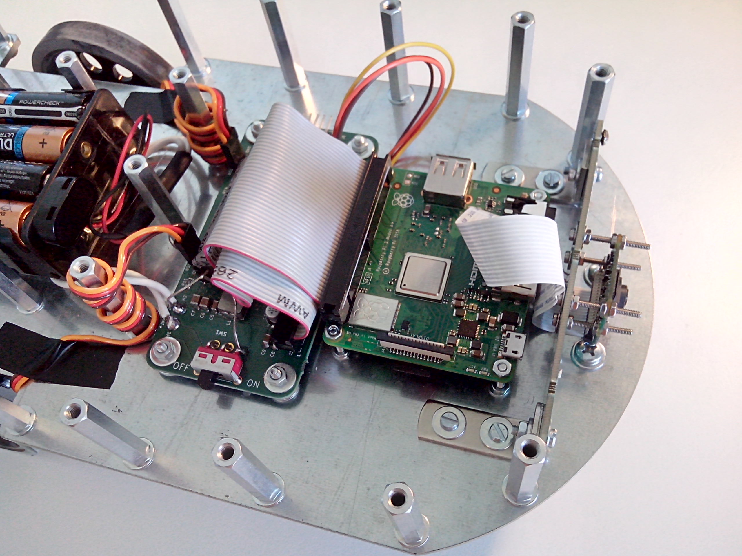
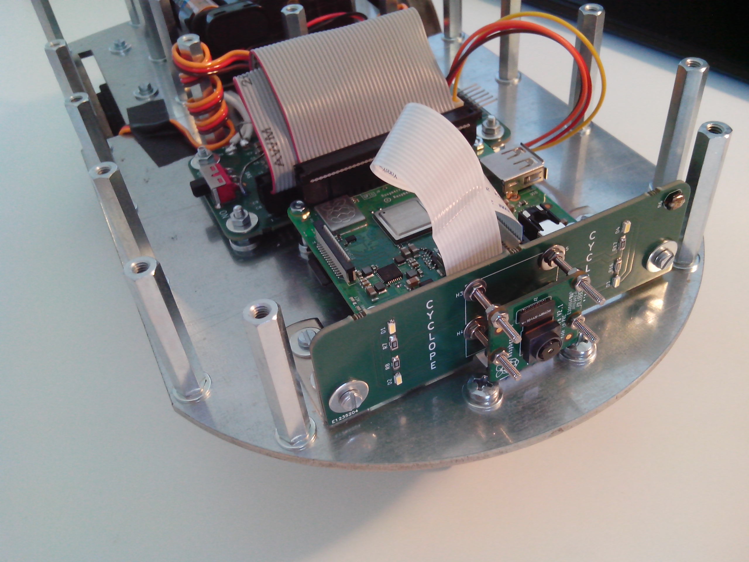
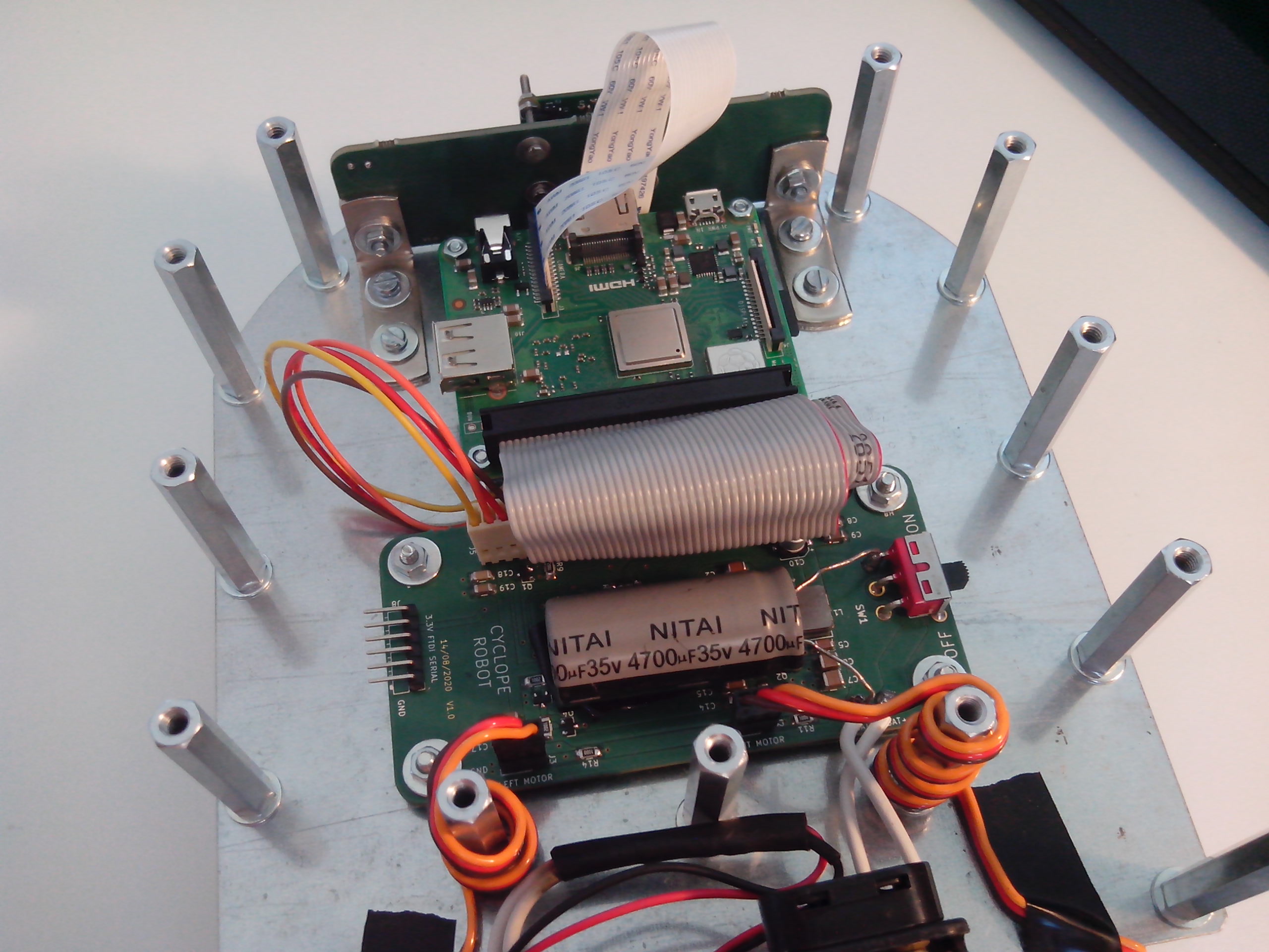
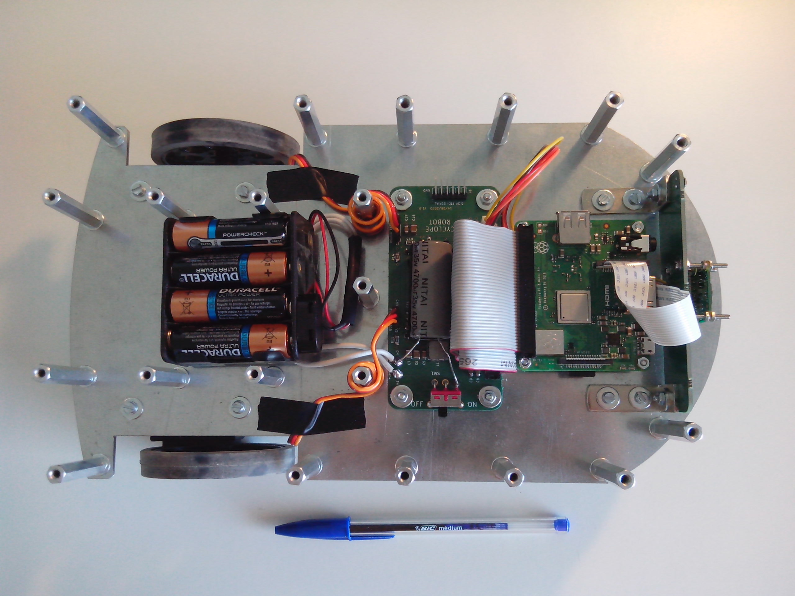
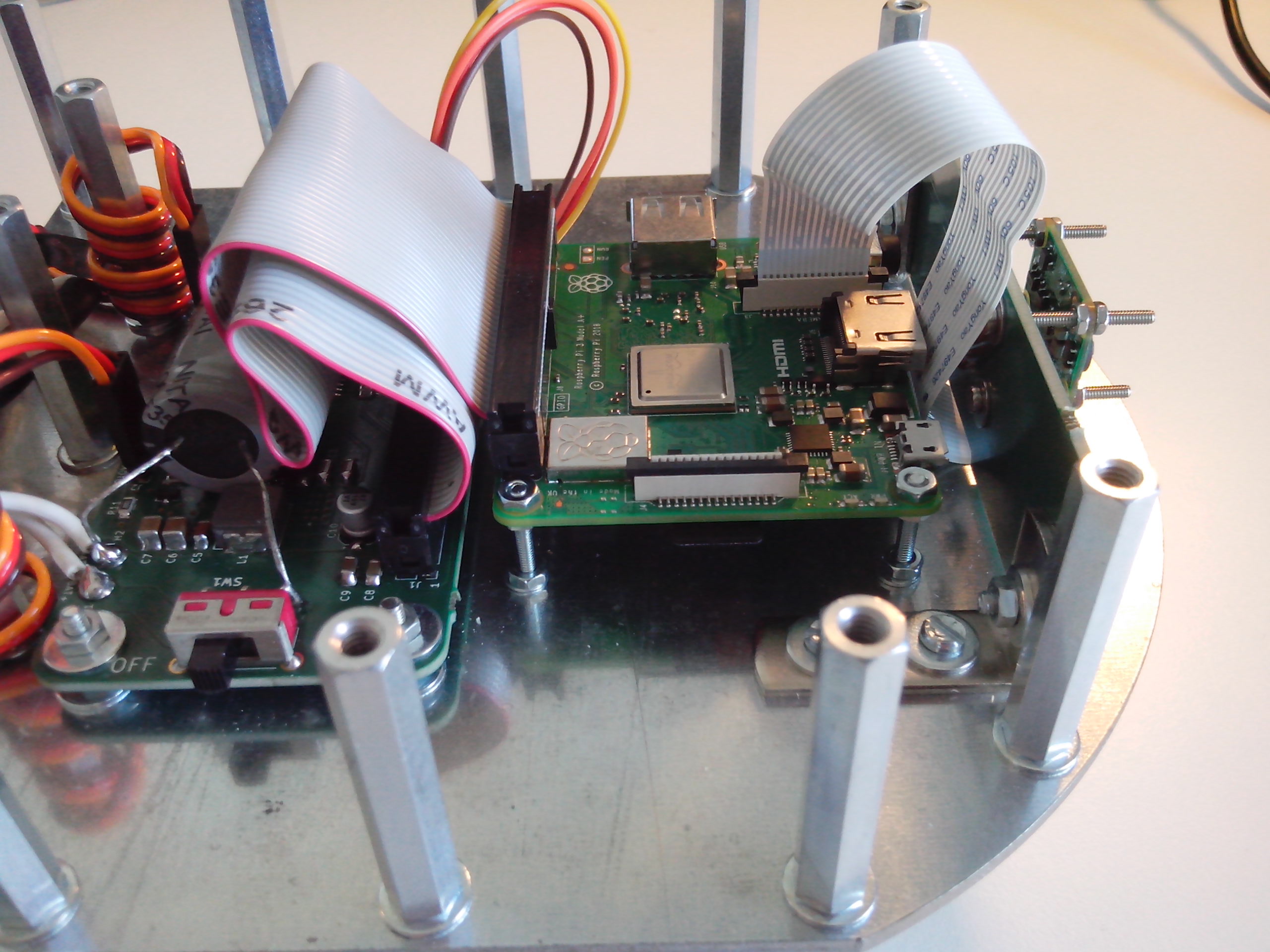
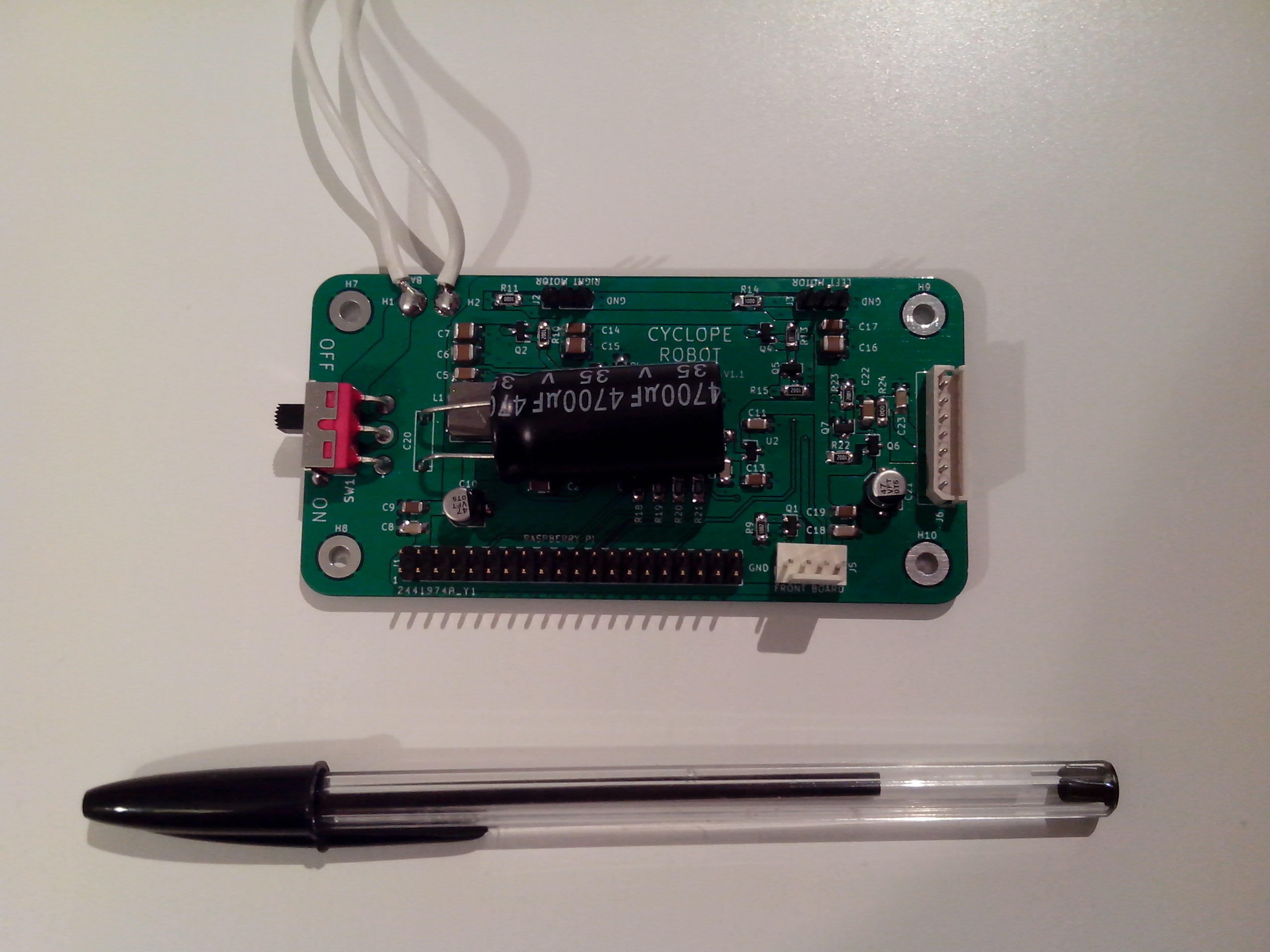
PCB has been soldered by hands (resistors array part was missing, I used normal 0805 resistors) :
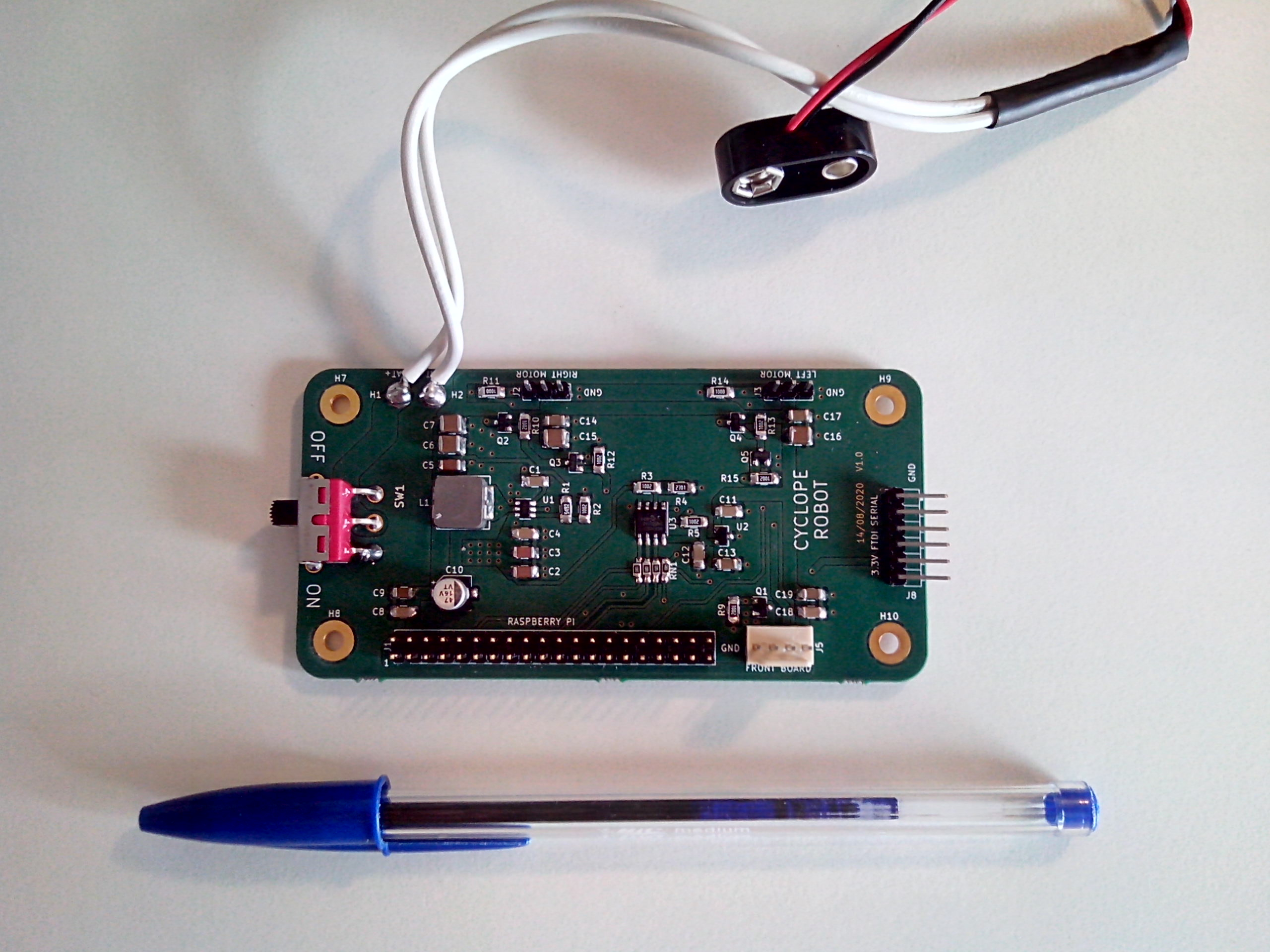
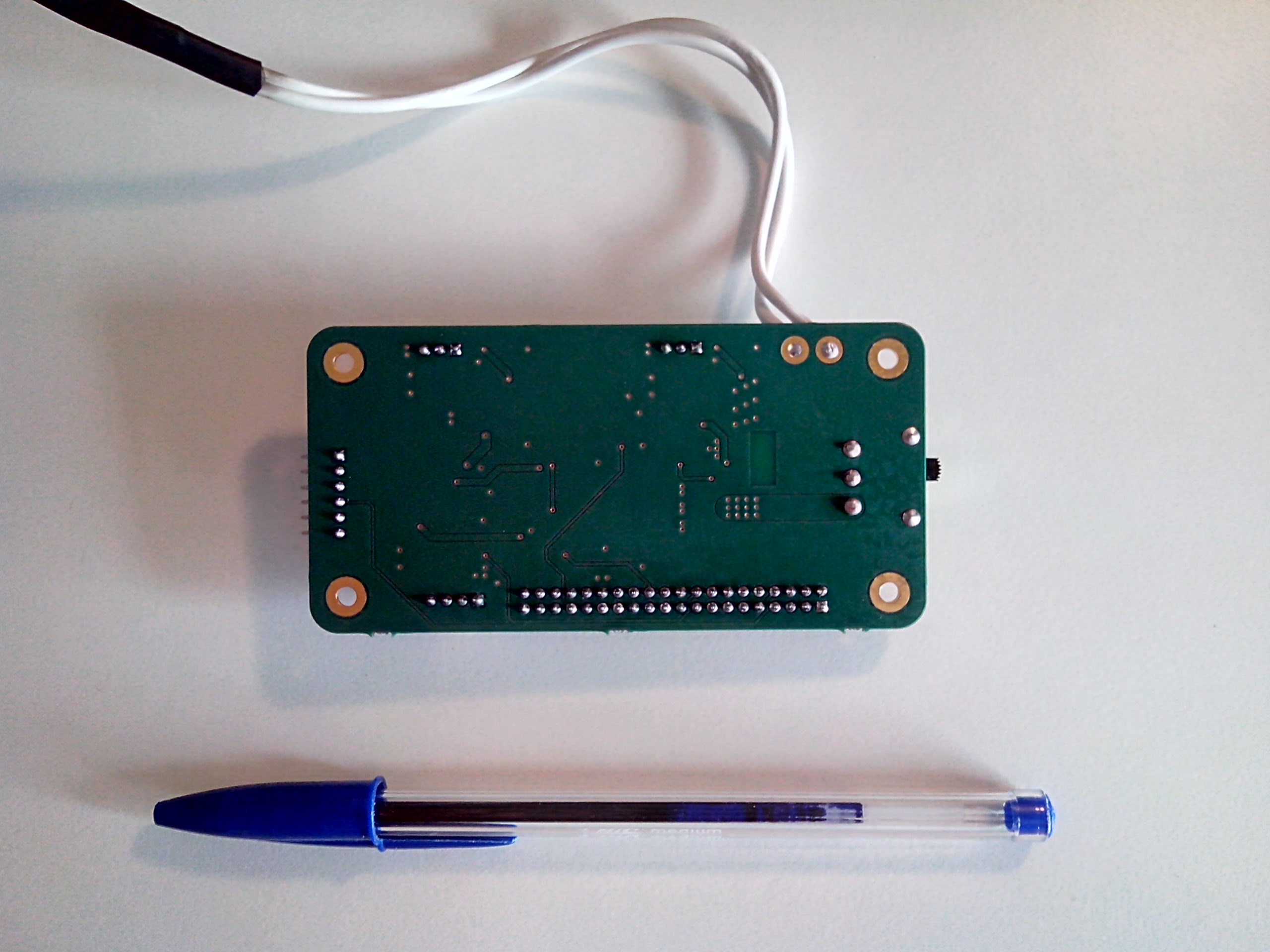
A big capacitor has been added to keep battery voltage stable when a lot of current is required :
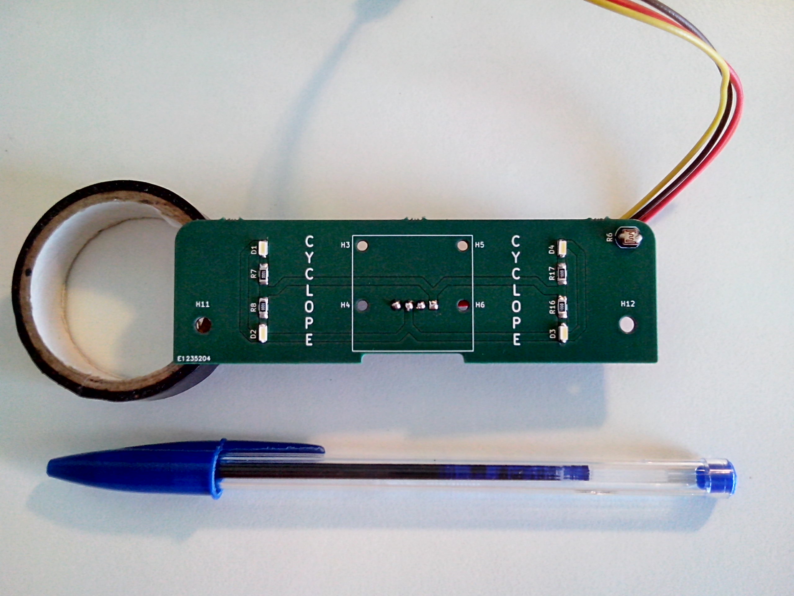
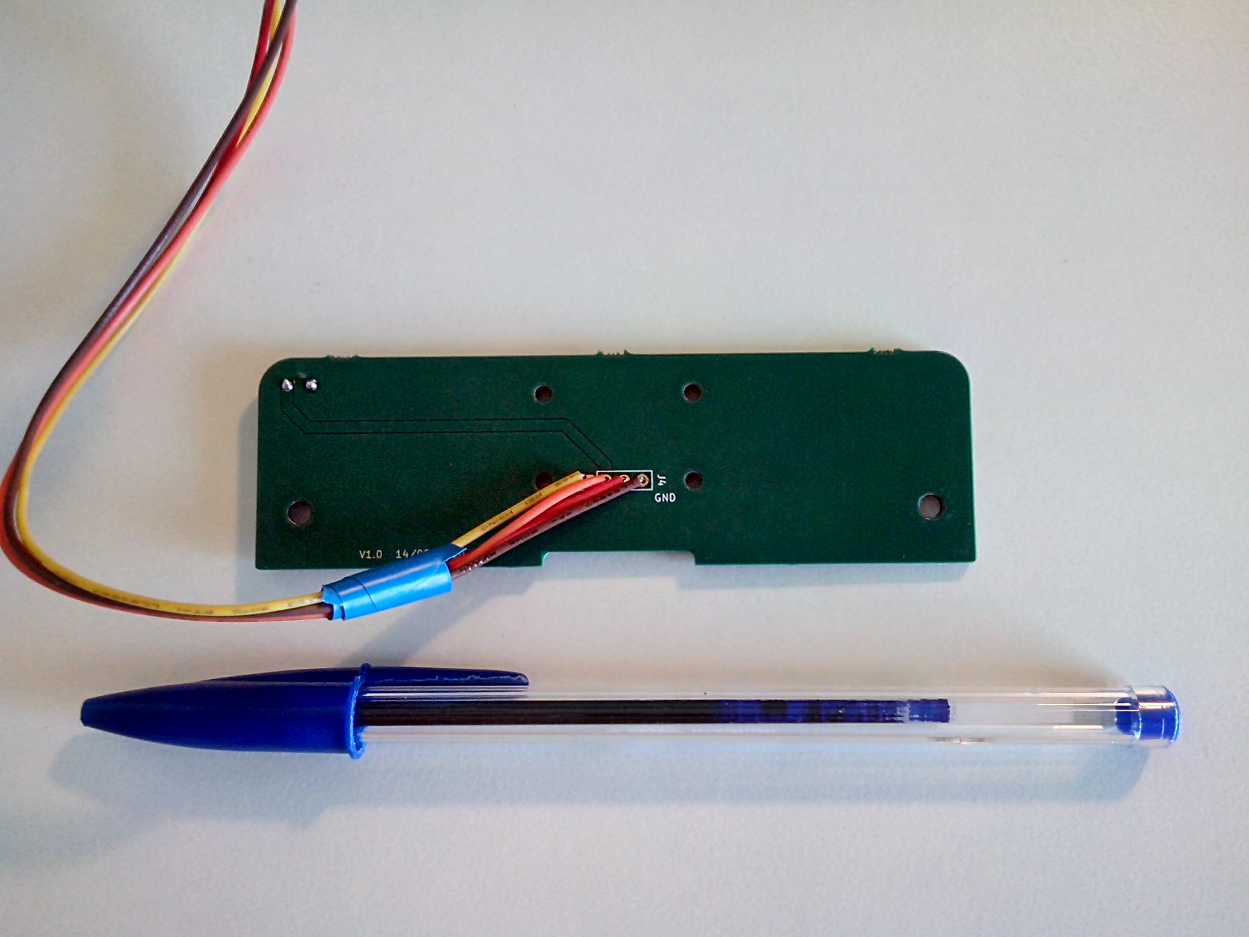
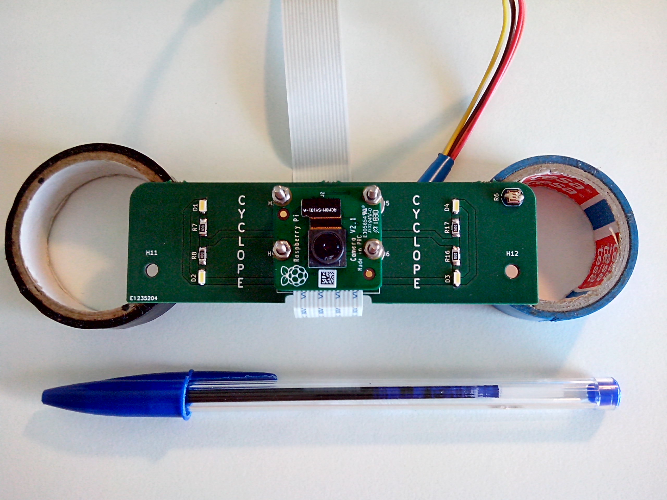
With Raspberry Pi Camera V2 mounted :
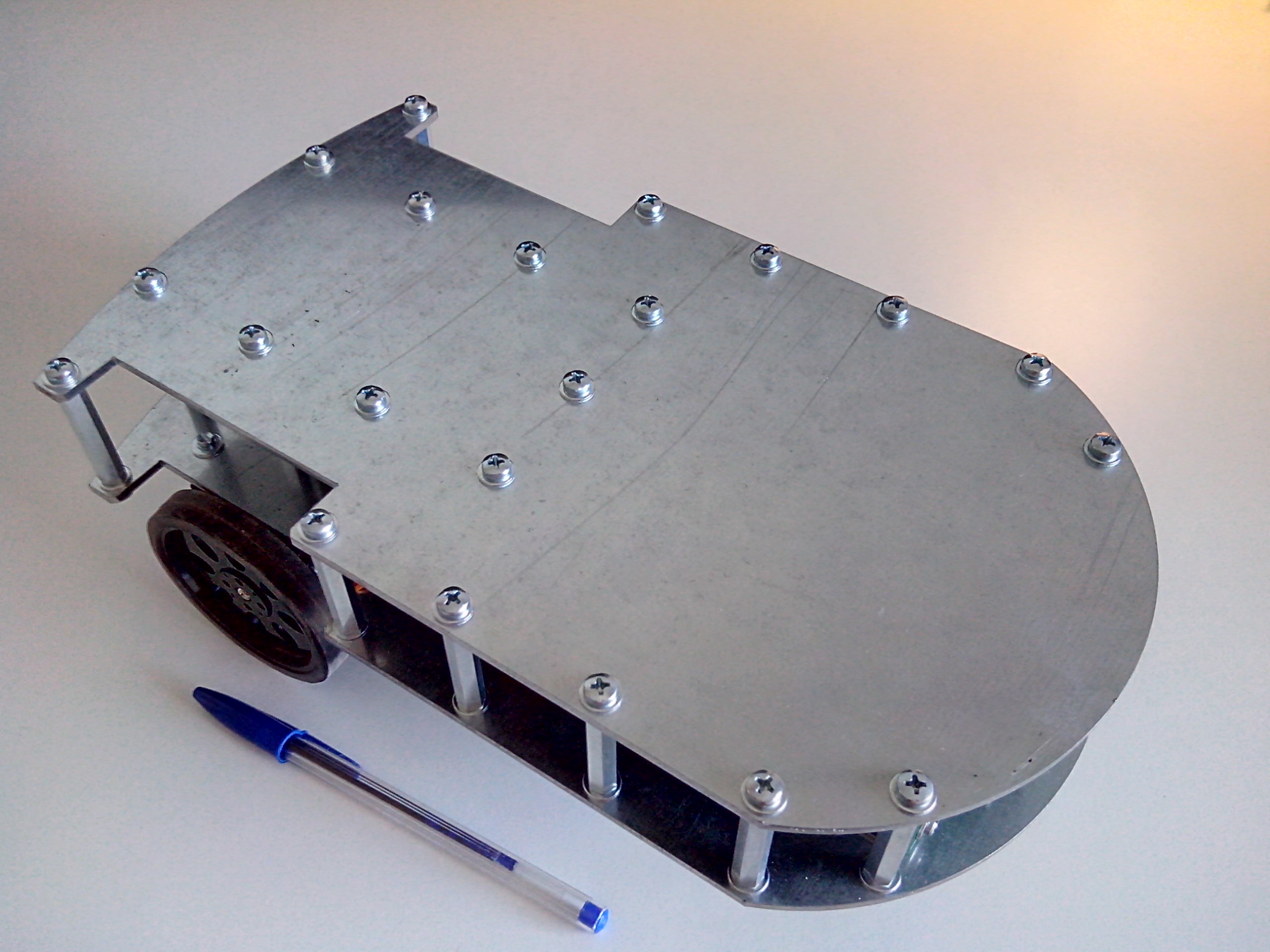
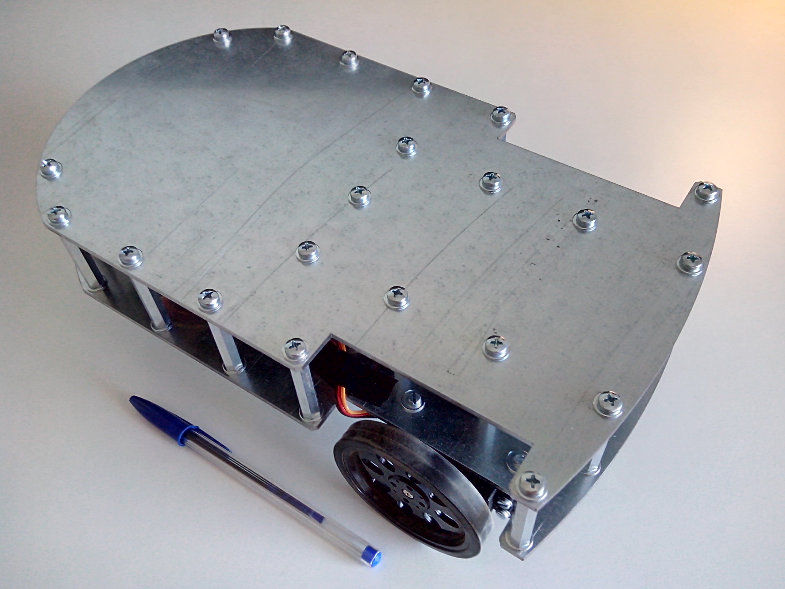
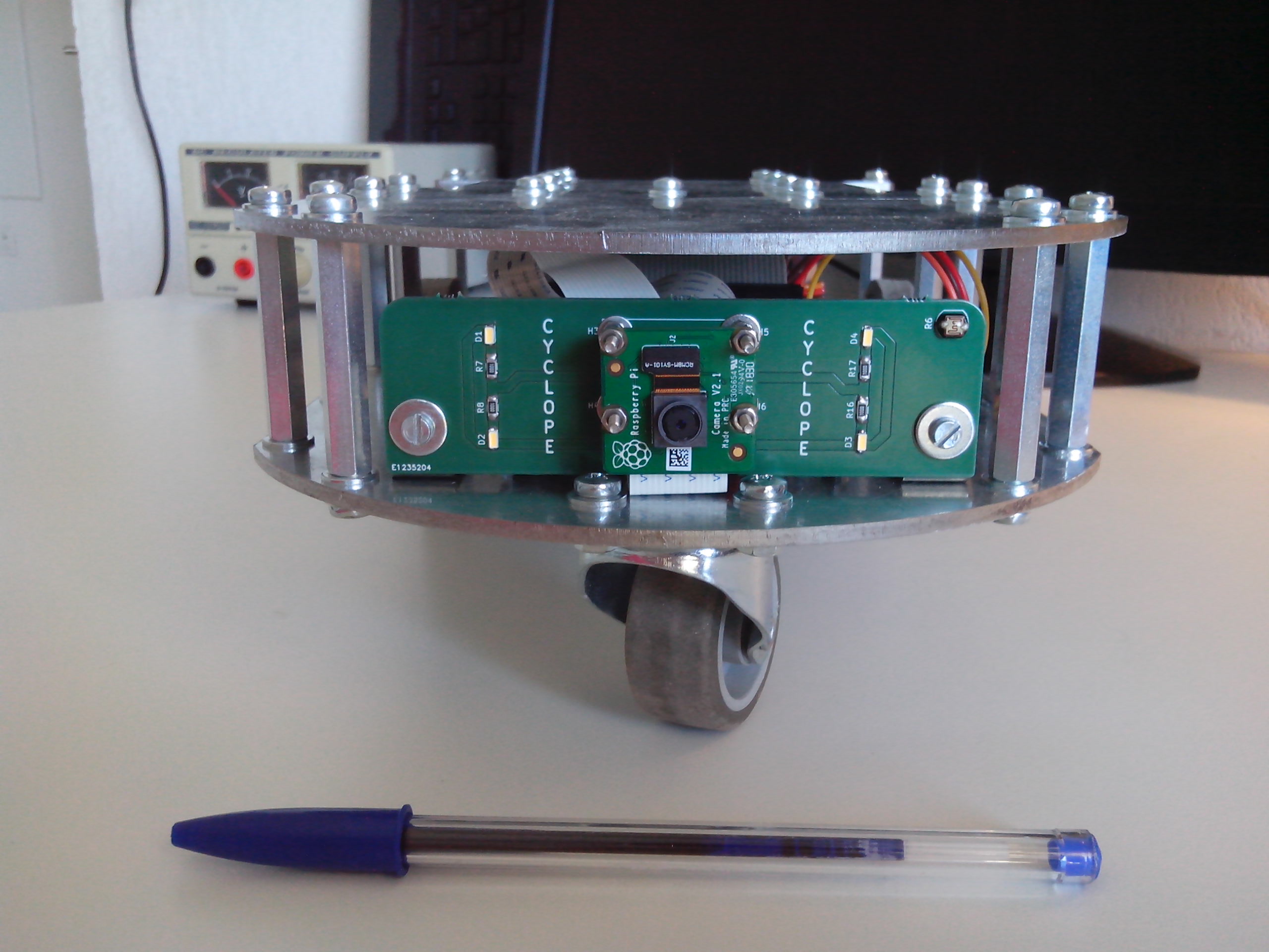
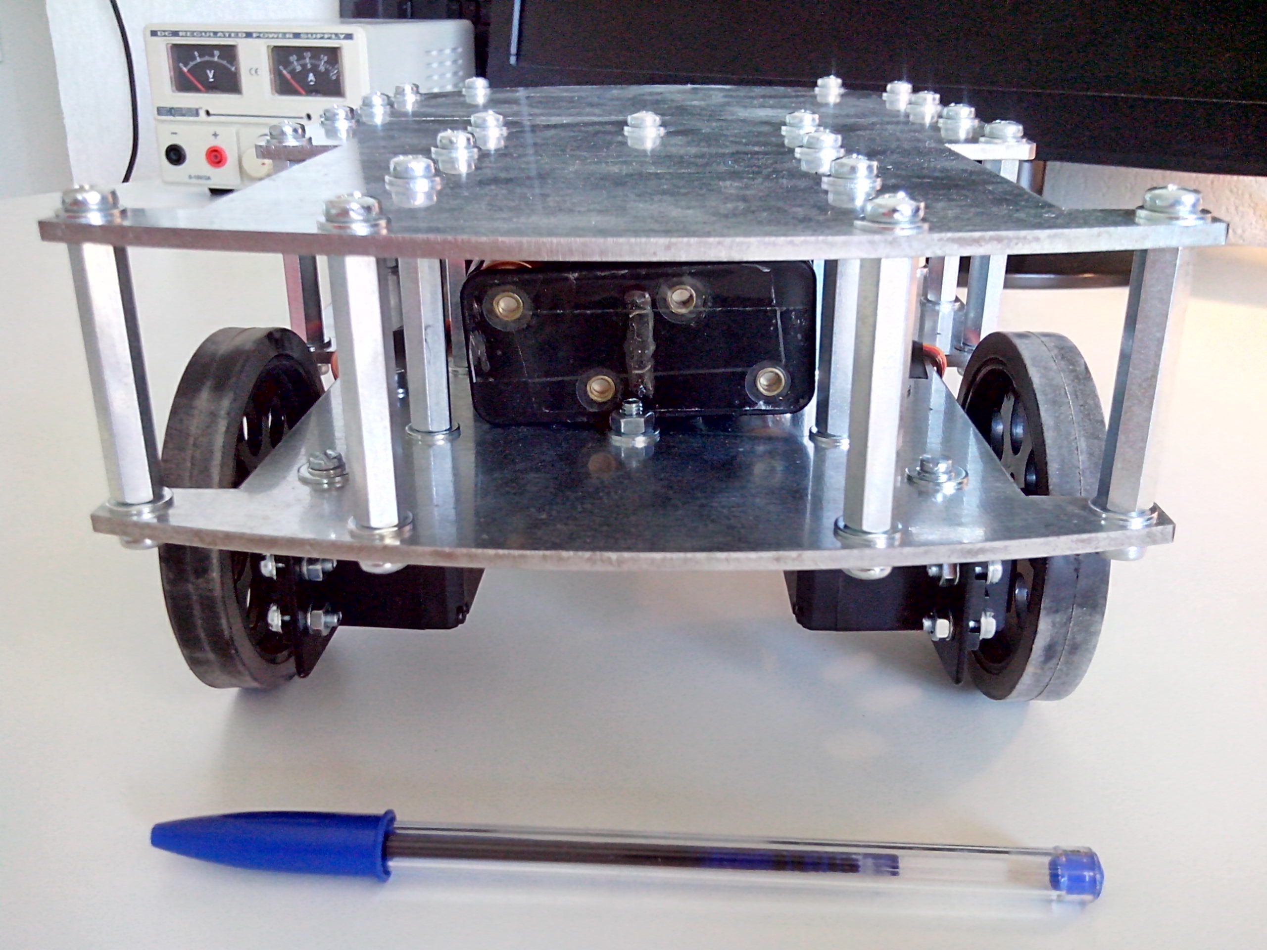
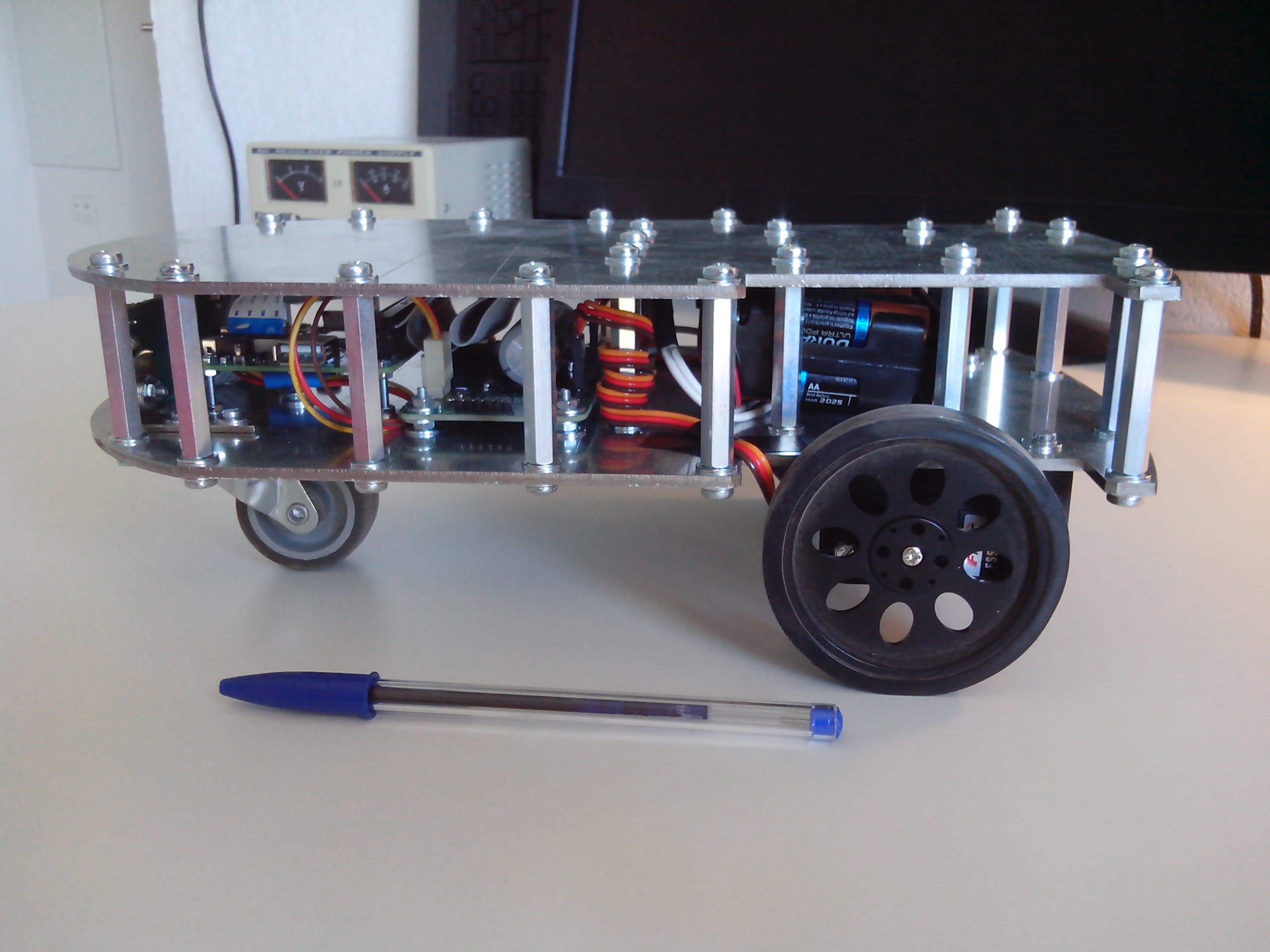
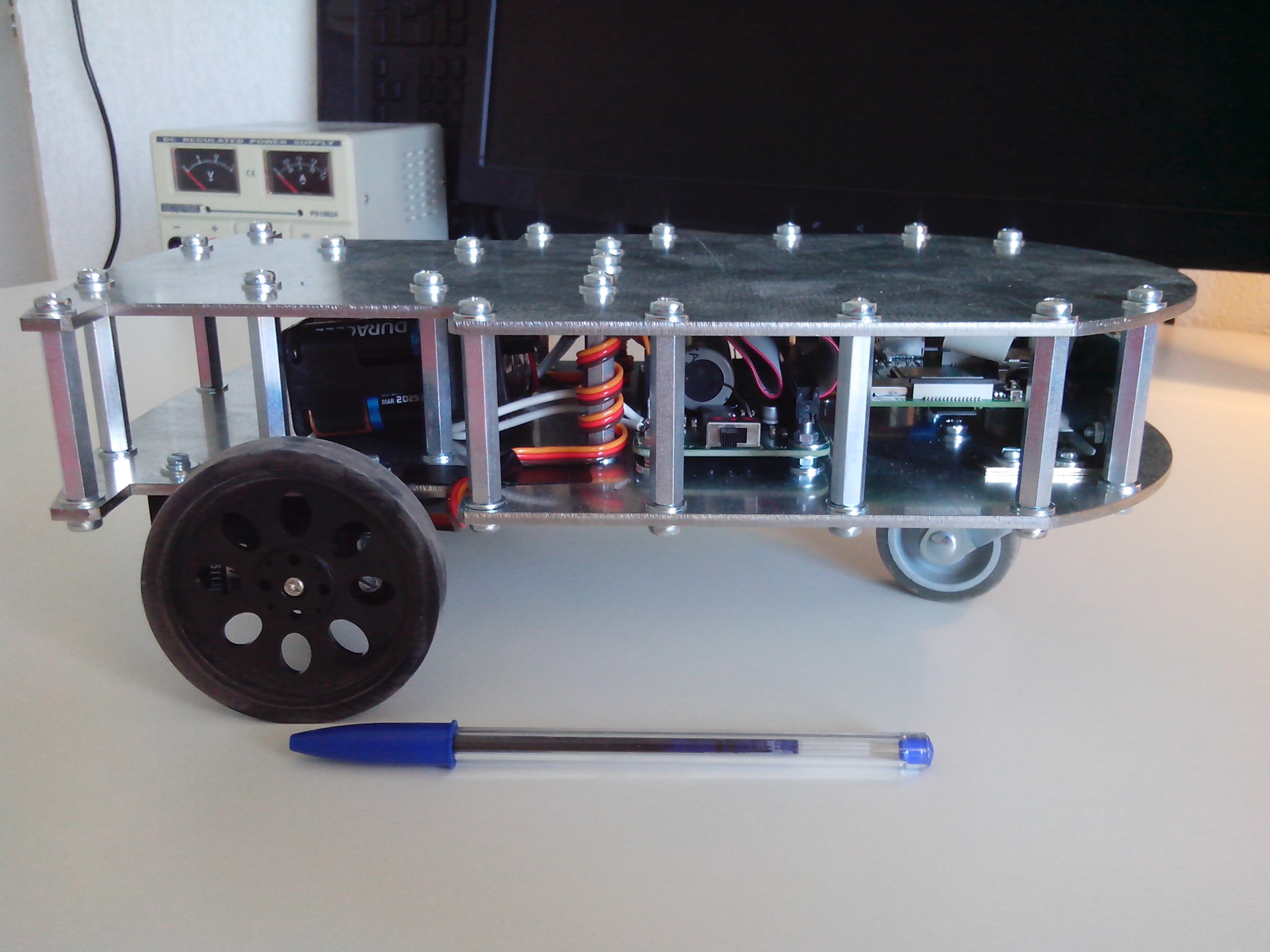
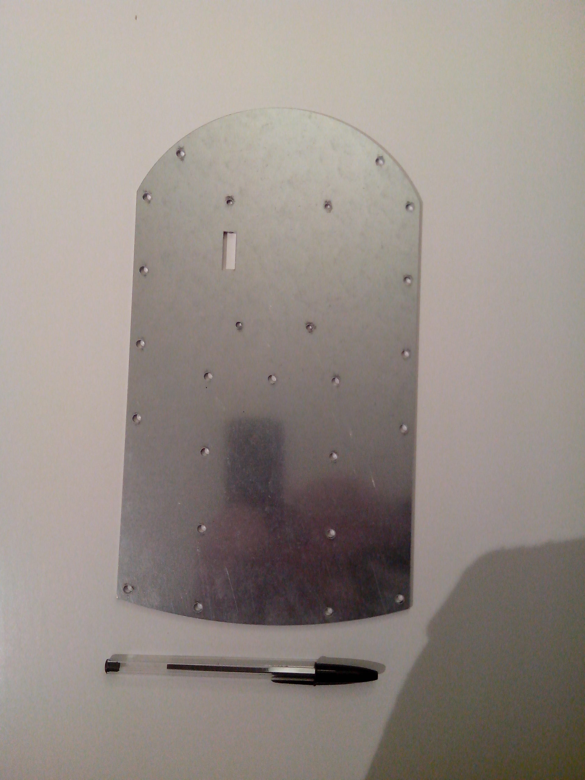
Chassis top plate with lidar holes :
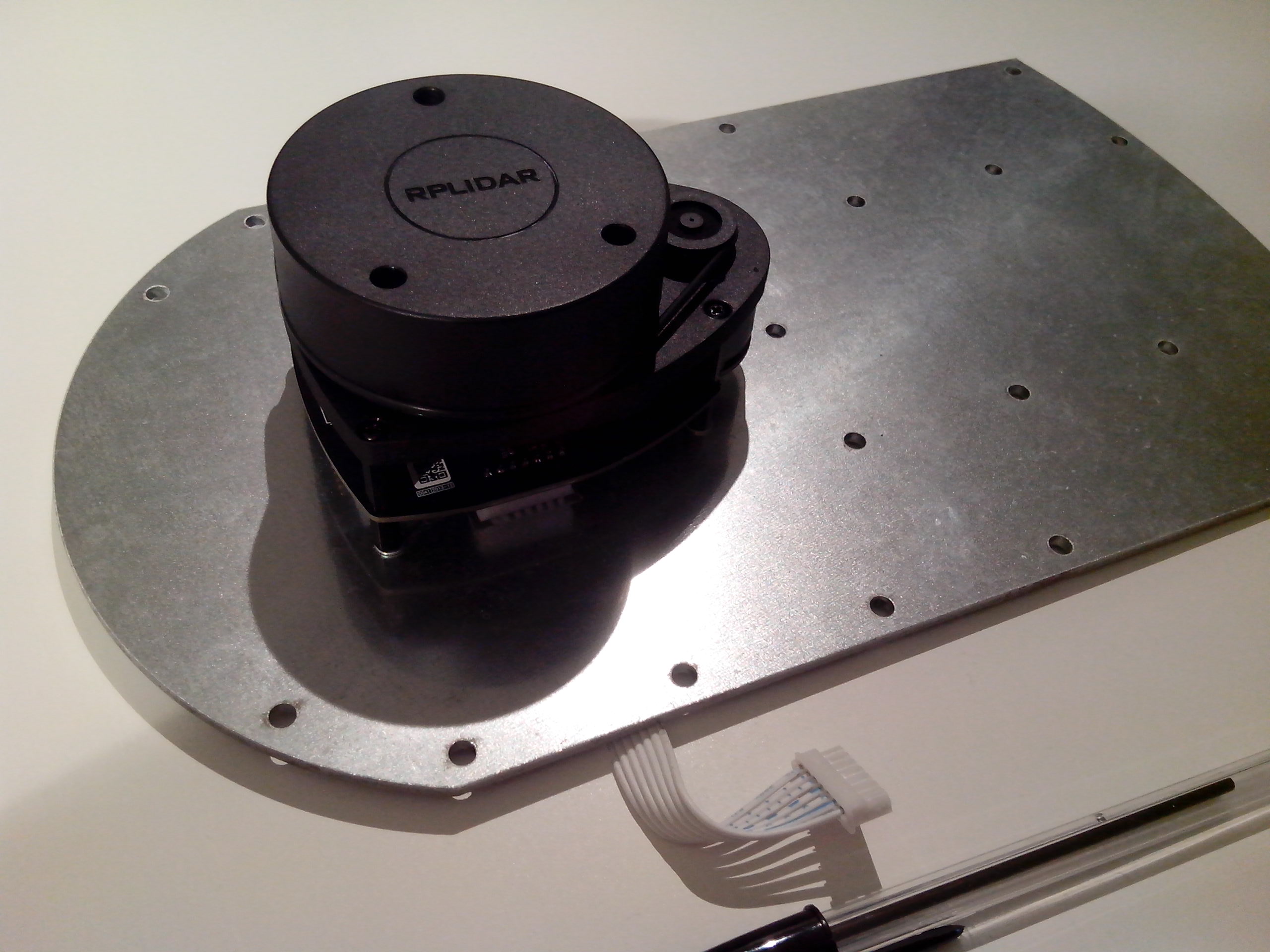
Lidar assembled on chassis top plate :
Motherboard PCB with lidar support :
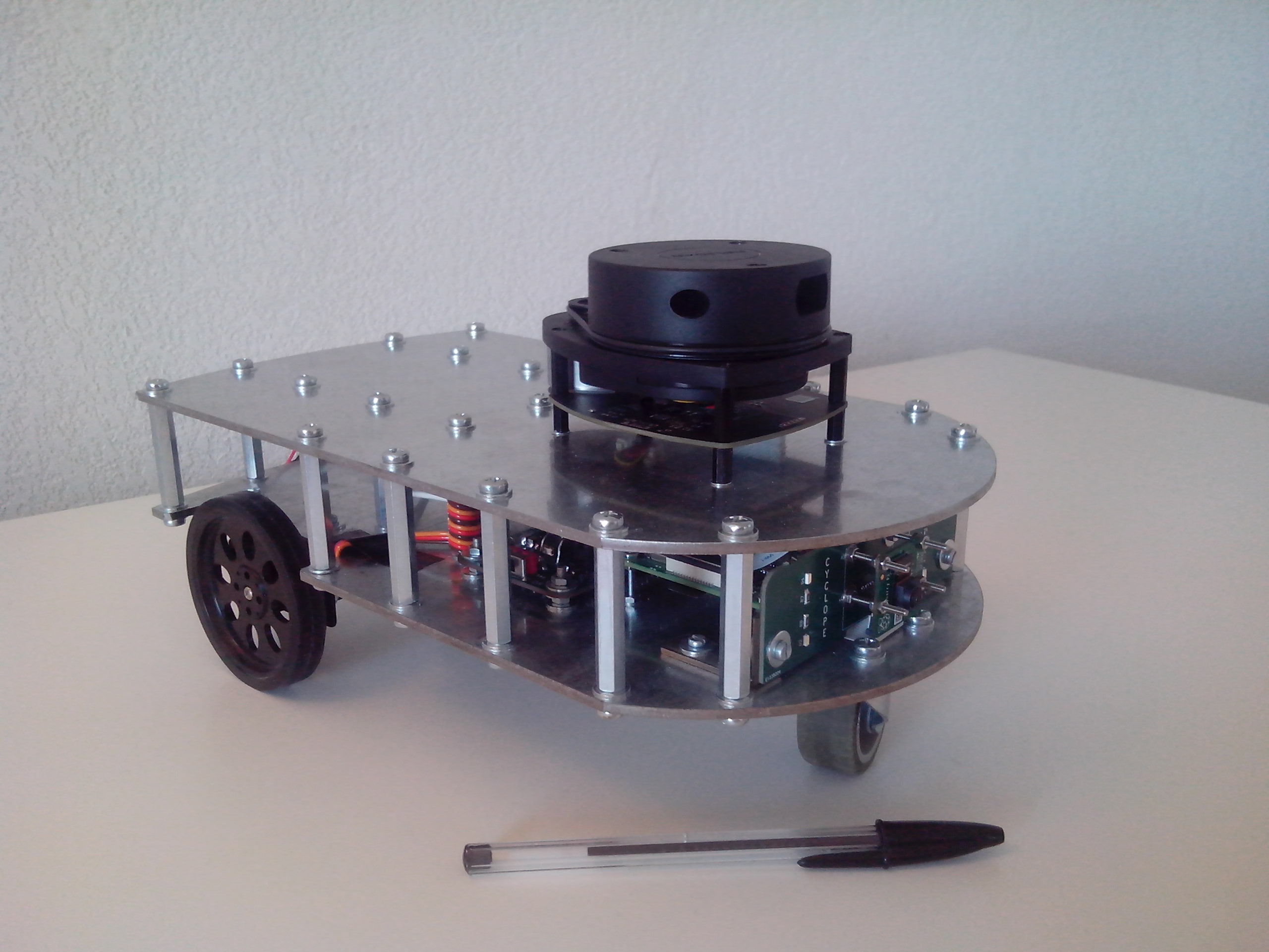
| Qty | Value | Footprint | References |
|---|---|---|---|
| 10 | 10K | Resistor_SMD:R_1206_3216Metric_Pad1.42x1.75mm_HandSolder | R2, R3, R5, R9, R10, R12, R13, R15, R22, R23 |
| 7 | 100n | Capacitor_SMD:C_1206_3216Metric_Pad1.42x1.75mm_HandSolder | C1, C4, C8, C11, C12, C18, C23 |
| 6 | 100 | Resistor_SMD:R_1206_3216Metric_Pad1.42x1.75mm_HandSolder | R7, R8, R11, R14, R16, R17 |
| 6 | BreakTab | Break_Tab:Break_Tab | BT1, BT2, BT3, BT4, BT5, BT6 |
| 5 | 2.2u | Capacitor_SMD:C_1206_3216Metric_Pad1.42x1.75mm_HandSolder | C9, C13, C14, C17, C19 |
| 4 | 10 | Resistor_SMD:R_1206_3216Metric_Pad1.42x1.75mm_HandSolder | R18, R19, R20, R21 |
| 4 | 10u | Capacitor_SMD:C_1206_3216Metric_Pad1.42x1.75mm_HandSolder | C2, C3, C5, C22 |
| 4 | 158301250 | 158301250:158301250 | D1, D2, D3, D4 |
| 4 | 22u | Capacitor_SMD:C_1210_3225Metric_Pad1.42x2.65mm_HandSolder | C6, C7, C15, C16 |
| 4 | Camera | MountingHole:MountingHole_2.2mm_M2 | H3, H4, H5, H6 |
| 4 | DMG3414U | Package_TO_SOT_SMD:SOT-23 | Q1, Q3, Q5, Q7 |
| 4 | Motherboard | MountingHole:MountingHole_3.2mm_M3_Pad | H7, H8, H9, H10 |
| 3 | DMG2301L | Package_TO_SOT_SMD:SOT-23 | Q2, Q4, Q6 |
| 2 | 47u | Capacitor_SMD:CP_Elec_5x5.4 | C10, C21 |
| 2 | Front | Connector_PinHeader_2.54mm:PinHeader_1x04_P2.54mm_Vertical | J4, J5 |
| 2 | Front_Board | MountingHole:MountingHole_3.2mm_M3 | H11, H12 |
| 1 | 0 | Resistor_SMD:R_1206_3216Metric_Pad1.42x1.75mm_HandSolder | R24 |
| 1 | 1101M2S3ABE2 | 1101M2S3AQE2:1101M2S3AQE2 | SW1 |
| 1 | 2.7K | Resistor_SMD:R_1206_3216Metric_Pad1.42x1.75mm_HandSolder | R4 |
| 1 | 22-03-5075 | Connector_Molex:Molex_SPOX_5267-07A_1x07_P2.50mm_Vertical | J6 |
| 1 | 4700u | Capacitor_THT:C_Rect_L9.0mm_W2.5mm_P7.50mm_MKT | C20 |
| 1 | 54.9K | Resistor_SMD:R_1206_3216Metric_Pad1.42x1.75mm_HandSolder | R1 |
| 1 | BATTERY+ | MountingHole:MountingHole_2.2mm_M2_Pad | H1 |
| 1 | BATTERY- | MountingHole:MountingHole_2.2mm_M2_Pad | H2 |
| 1 | IHLP3232DZER3R3M01 | IHLP3232DZER3R3M01:IHLP3232DZER3R3M01 | L1 |
| 1 | LDR07 | OptoDevice:R_LDR_5.1x4.3mm_P3.4mm_Vertical | R6 |
| 1 | M20-9762042 | Connector_PinHeader_2.54mm:PinHeader_2x20_P2.54mm_Vertical | J1 |
| 1 | MCP3002 | Package_SO:SOIC-8_3.9x4.9mm_P1.27mm | U3 |
| 1 | MP000303 | Supply_Part:Supply_Part | BAT1 |
| 1 | Motor_1 | Connector_PinHeader_2.54mm:PinHeader_1x03_P2.54mm_Vertical | J3 |
| 1 | Motor_2 | Connector_PinHeader_2.54mm:PinHeader_1x03_P2.54mm_Vertical | J2 |
| 1 | NCP51460SN33T1G | Package_TO_SOT_SMD:SOT-23 | U2 |
| 1 | TPS565208DDC | Package_TO_SOT_SMD:SOT-23-6 | U1 |

CopperPilot/Jetson-AI-Cam-CopperPilot
A carrier for Jetson Nano, Xavier NX and TX2 NX with two IMX219 cameras on a 39 mm stereo baseline, dual 4K outputs and CAN.


henry-thomas-1/ECE-445-Smart-Tripod
The above files are set as Handheld, however they are the files for the motorized tripod. Backups are included of the files over minor changes and major changes to the PCB.


It measures 100 × 84 mm and has 2 copper layers, 1.6 mm thick.
88 parts, built around the MCP3002-I/P, TPS565208DDC, DMG3414U and DMG2301L. The full list of its parts is on this page, with links to each part's symbol and footprint where PCBKit's library has them.
From the RICCIARDI-Adrien/Cyclope repository on GitHub, at the commit this page was made from: the board is Hardware/Cyclope.kicad_pcb and its schematic Hardware/ADC.kicad_sch. PCBKit opens the board in the browser, with nothing to install.
Its repository publishes it under the MIT licence: you may reuse it on that licence's terms (keep the author's notice, and for a copyleft licence share your changes alike).